


LWDF IIR Filter Design Examples
If you made it this far through the math wilderness, congratulations, it's time now to put all that knowledge to good use and design some LWDF IIR filters. I will start with some simple ones first, graduating then to some awesome IIR filters, especially when compared to their FIR equivalents.
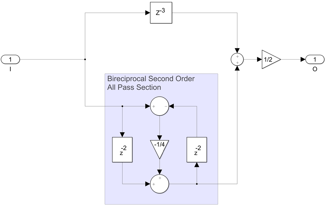
The simplest LWDF filter possible is of degree 3, remember the filter order has to be odd and there isn't much you can do with a degree one filter. A 3rd order bireciprocal LWDF IIR consits of one delay in the odd path (which is actually a first order all pass section with the coefficient set to zero) and a second order all pass section with the first coefficient zero in the even path. It turns out that the only value that makes sense for the single non-zero coefficient that leads to a filter with a meaningful pass and stop band is 0.5:
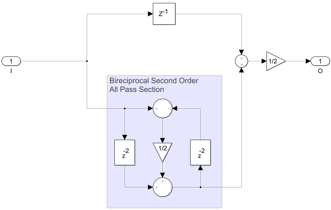
This is a very simple filter, multiplierless actually since in hardware multiplying by any power of 2 is free. Not only that, but the second order all pass section can be implemented with a single 3-input CSA adder while the final adder can also do rounding with another 3-input CSA adder. So the entire filter is just two adders and some FFs. This can also run easily at over 800Sps rates.
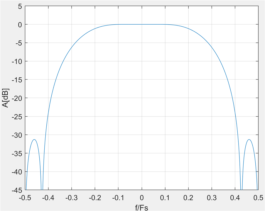
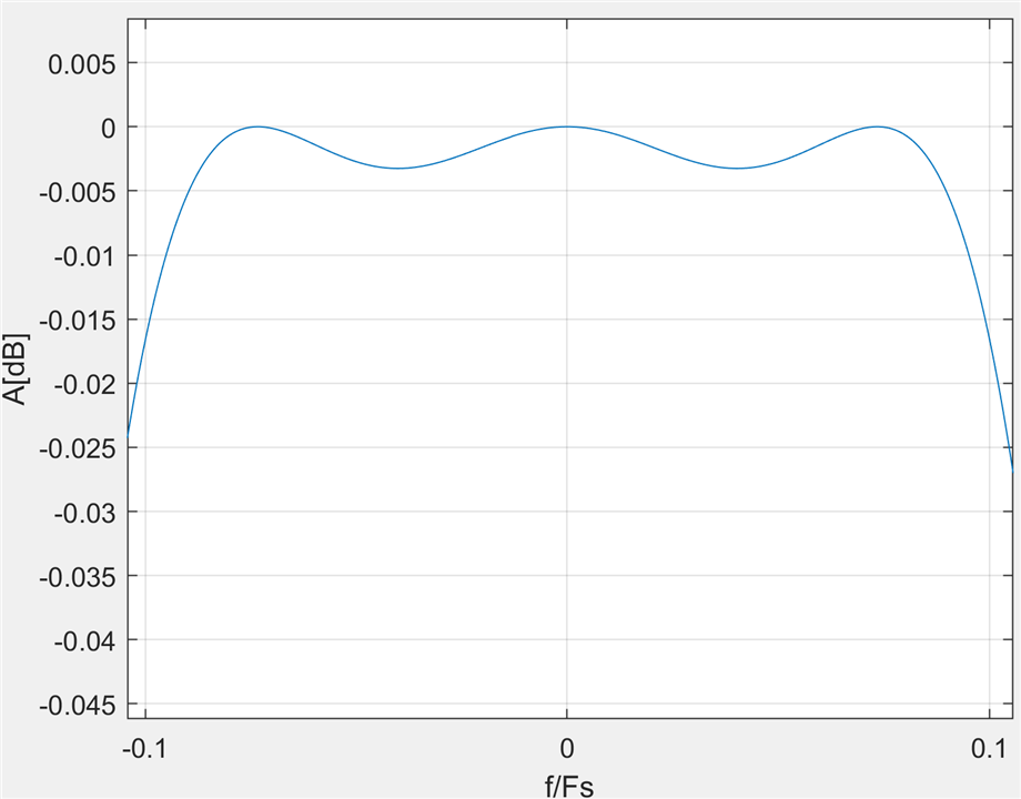
Yes, the transfer function is not very impressive, with a stop band attenuation of only 22dB, but what did you expect from just two adders?
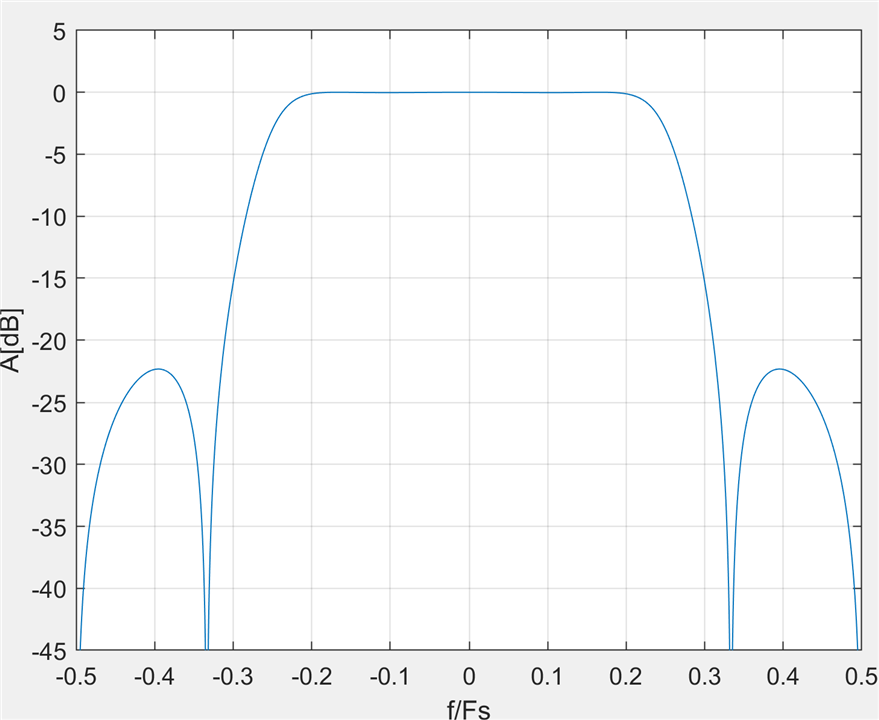
However, the redeeming fact is the relatively flat pass band with just 0.025dB of ripple:
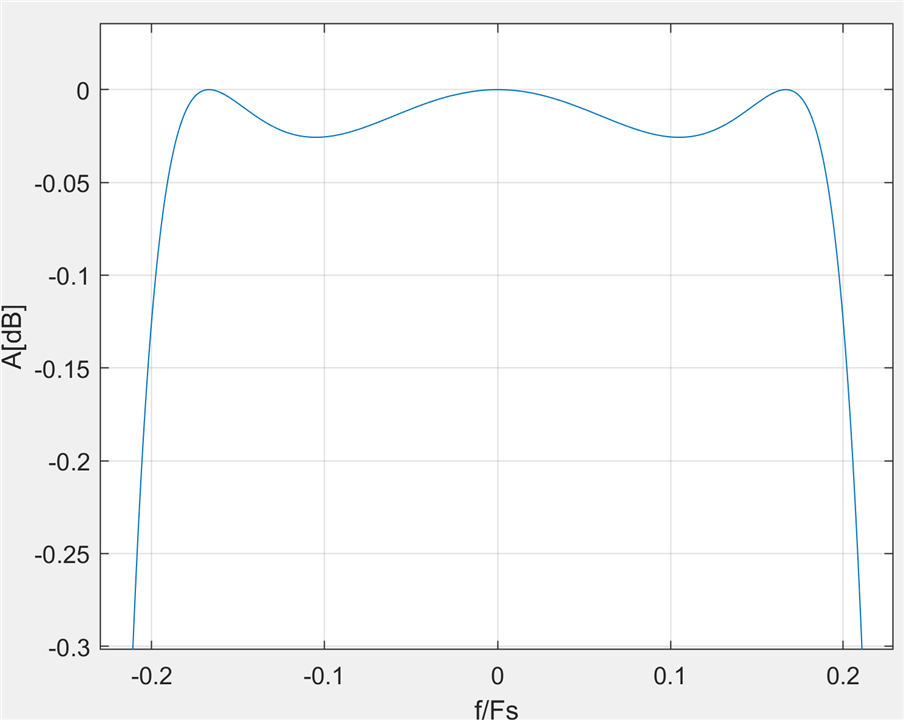
which lets us cascade multiple instances of this filter and achieve a much better result. With four instances of this super simple filter in series, it starts to get quite impressive - 0.1dB pass band ripple and 88dB stop band attenuation, achieved with no multipliers and just 8 adders!
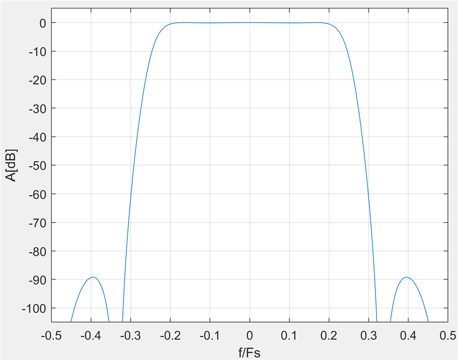
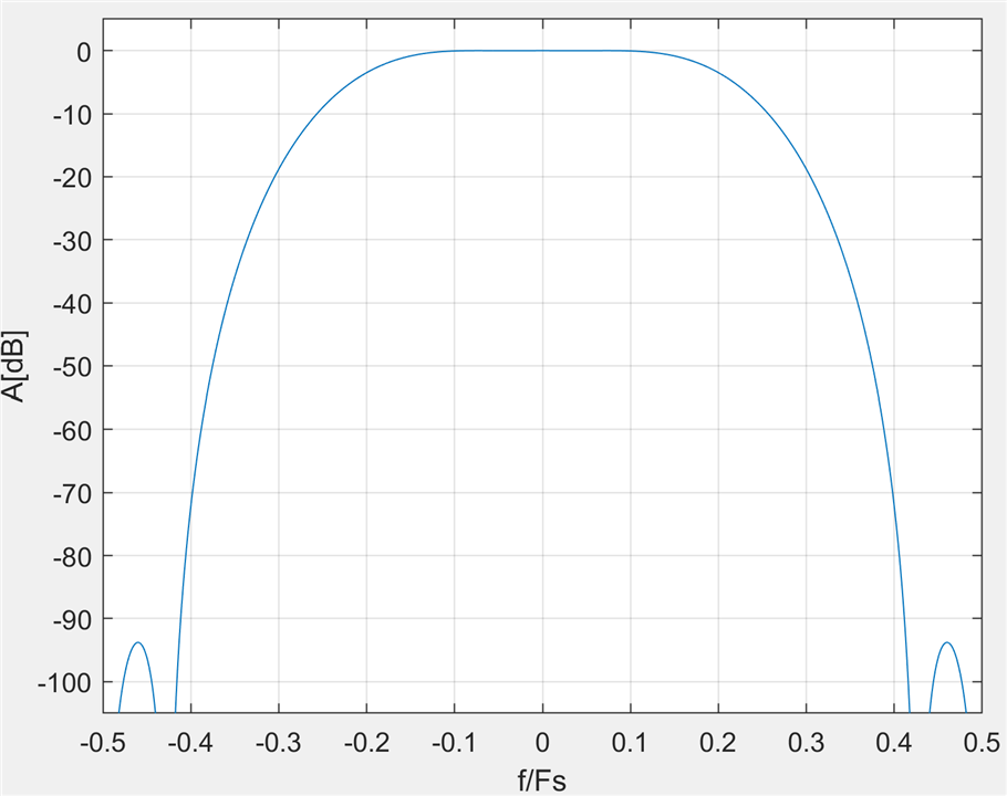
Another similar filter is the next simplest LWDF IIR, a 5th order one, similar to the previous example except that the odd path is now longer at 3 delays (one first order and one second order section, with all three coefficients set to zero). The only non-zero coefficient value that leads to a flat passband is now -0.25, yet another power of two, so this one too is also multiplierless:
The transition band is wider now but the stop band attenuation is 31dB and there is even less passband ripple, just 3mdB:
Cascading 3 such instances leads to another very impressive multiplierless filter, which requires no multipliers, only six adders, and can run at a sample rate equal to the full clock speed of the FPGA:
It has 10mdB pass band ripple, f_p/Fs=0.087, 93dB stop band attenuation, f_s/Fs=0.413, very respectable for a multiplierless filter. The equivalent halfband FIR has order 15 and requires four multipliers. Of course the FIR has linear phase while the IIR doesn't, but if linear phase is not a requirement then the IIR filter wins by a mile.
Now let's consider a mid-range filter, FS=1000MHz, f_p=240MHz, a_p<0.1mdB, f_s=260MHz, a_s=100dB. An Elliptic bireciprocal IIR filter of order 21, that uses 10 multiplications meets these requirements:
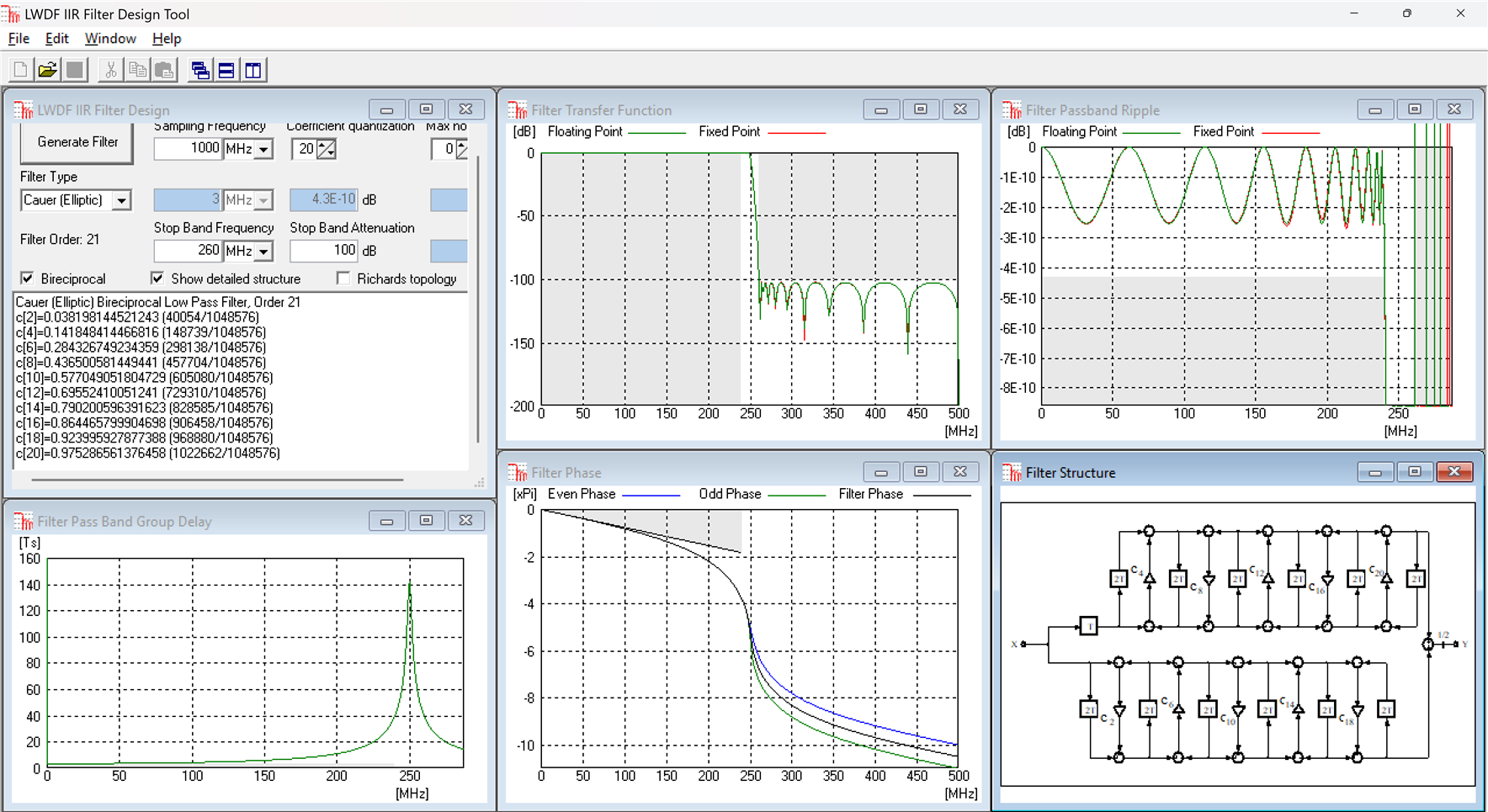
The equivalent halfband FIR has order 303 and uses 76 multiplications, 7.6x more than the IIR filter.
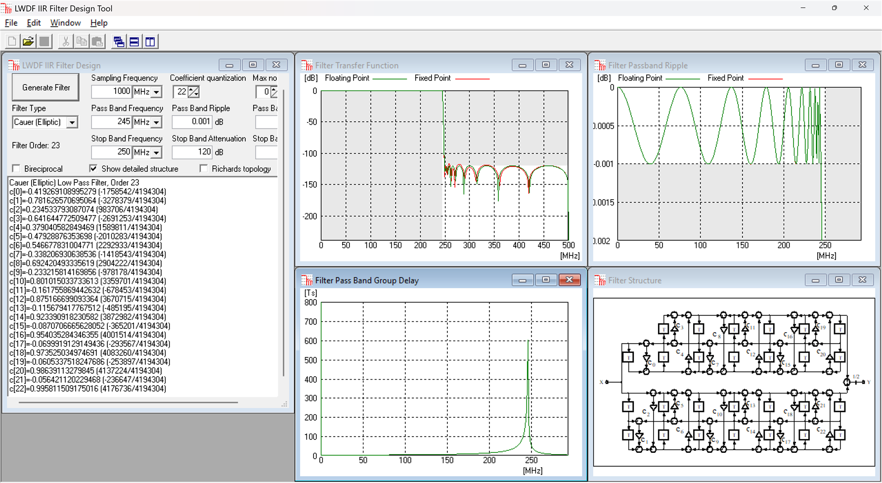
Finally, an extreme filter design example, F=1000MHz, f_p=245MHz, a_p=1mdB, f_s=250MHz, a_s=120dB. This one is no longer bireciprocal or halhband and this a very tough set of requirements, something you may encounter in test and measurement equipment for example. Here is the Elliptic LWDF IIR design, of order 23, with 23 multiplications:
The equiripple FIR design almost breaks the Matlab filter design tool, with an FIR with N=1229. This is symmetric but not halfband, so 615 multipliers are needed:
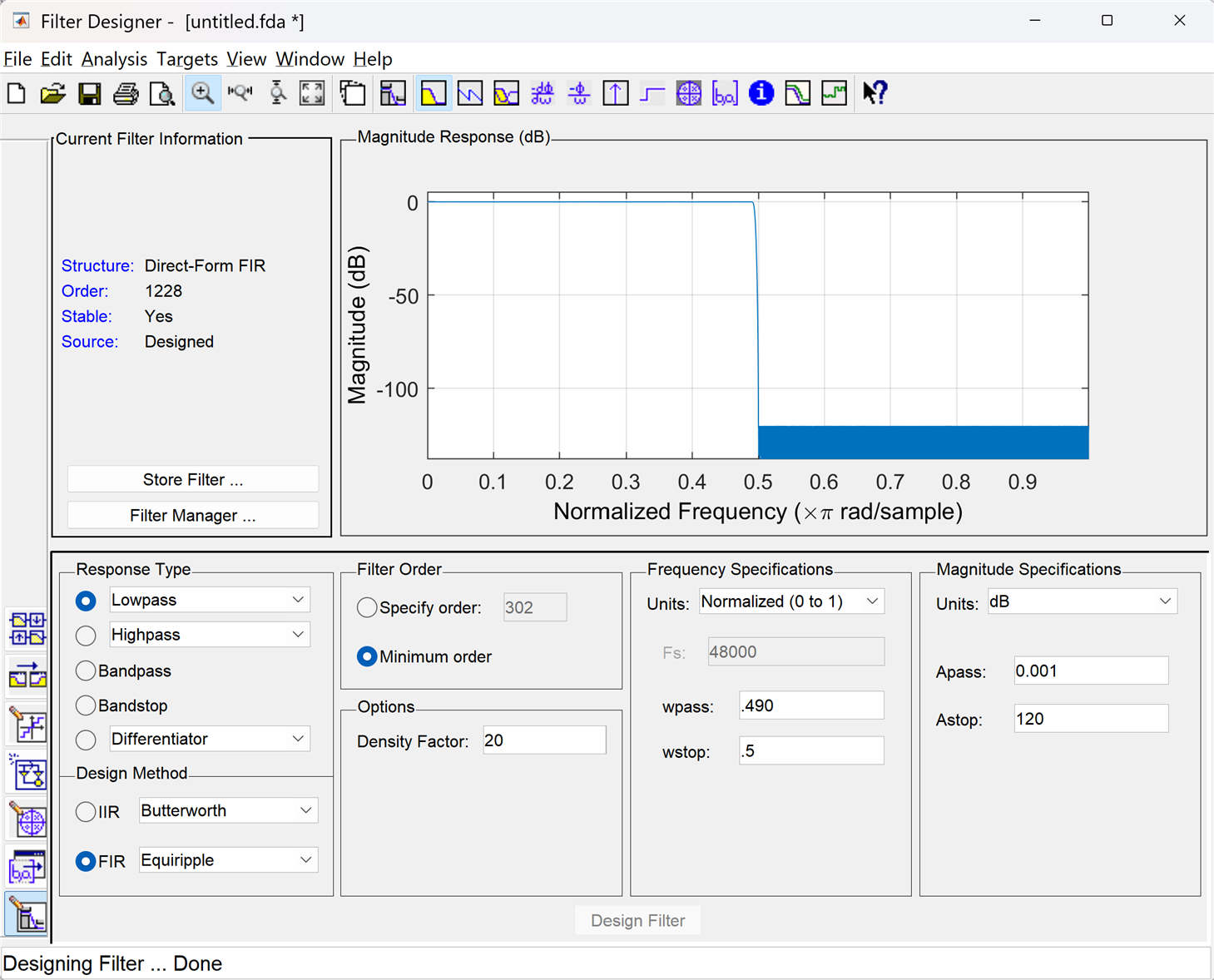
That's a factor of 26.7x in savings for the IIR!
Very well, you will say, but this is not a fair comparison. For the vast majority of filter designs linear phase is important and by definition symmetric FIRs have it, while IIRs, also by definition, don't.
I do have an answer for that but it will have to wait for the next blog post.
Back to the top: The Art of FPGA Design Season 2
