


Look Ma, no multipliers!
The last LWDF IIR filter example I gave was unusual in the sense that it was multiplierless, all the coefficients were powers of two, which in FPGA hardware cost absolutely nothing. Of course, this restricts considerably the kind of transfer functions that can be achieved, even when using tricks like cascading multiple instances of the same simpler filter.
We have seen that the adders and multipliers in the first and second order all pass sections map very well into the FPGA DSP blocks, with their pre-adder, multiplier and post-adder, especially if you can somehow arrange four delays in the feedback loops to achieve full pipelining. Earlier Xilinx FPGA families like 7-Series and UltrScale (but not the latest Versal one) have a very nice feature that lets you do a 3-input adder with the same resources and pipelining requirements of a simple 2-input adder. Named Carry Save Adder, or sometimes 3:2 compressor, it gives you an extra free adder for every normal ripple carry chain binary adder you use.
If the multiplier coefficient is a power of two, or a sum or difference of a small number of powers of two, it is possible to map the entire multiplier, plus the pre and post adders into an equally small number of 3-input adders, while at the same time achieving full pipelining with two register levels instead of the usual four a DSP primitive requires.
Below are examples of optimal implementations of all pass sections when the coefficient has 1, 2, 3 respectively 4 non-zero bits. An extra degree of freedom can be gained by considering both positive and negative non-zero bits, since subtraction doesn't cost anything extra. For example, 31/64 does not have five non-zero bits, i.e. (16+8+4+2+1)/64, it only has two, (32-1)/64.
The simplest case we have already encountered is a single non-zero bit, or a power of 2. For example, if c=1/2:
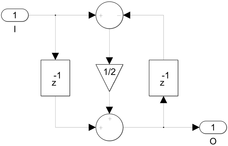
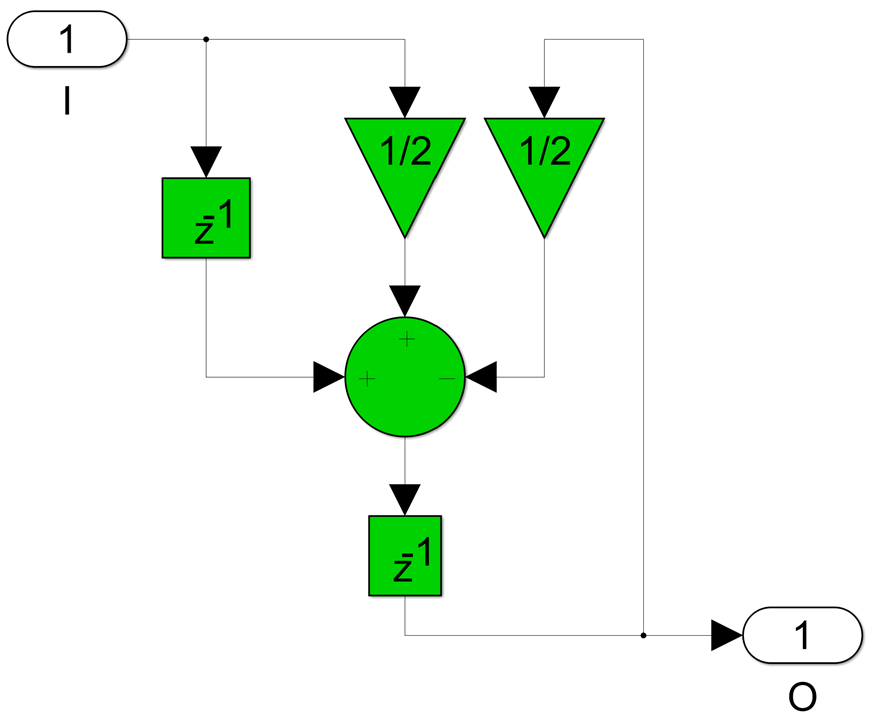
we can replace the two adders and the multiplier with a single 3-input adder, without the need of introducing any extra registers:
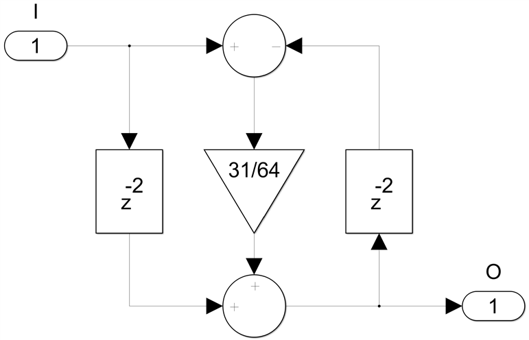
For 2, 3 or 4 non-zero coefficient bits we need two register levels for full pipelining. For the 2 non-zero bit case I will use c=31/64 as a numerical example:
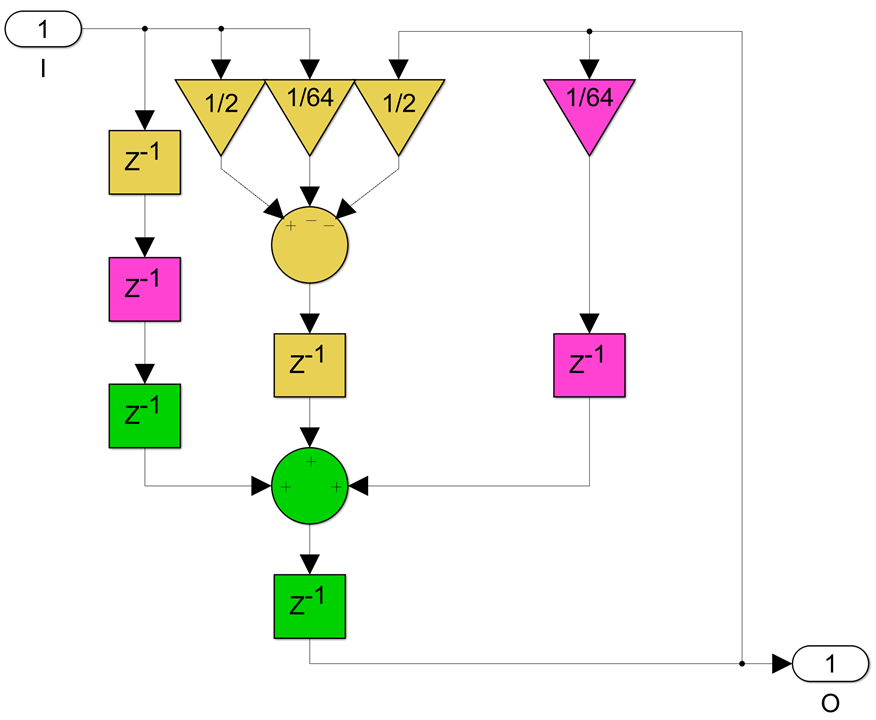
Now two 3-input adders and some extra FFs are needed:
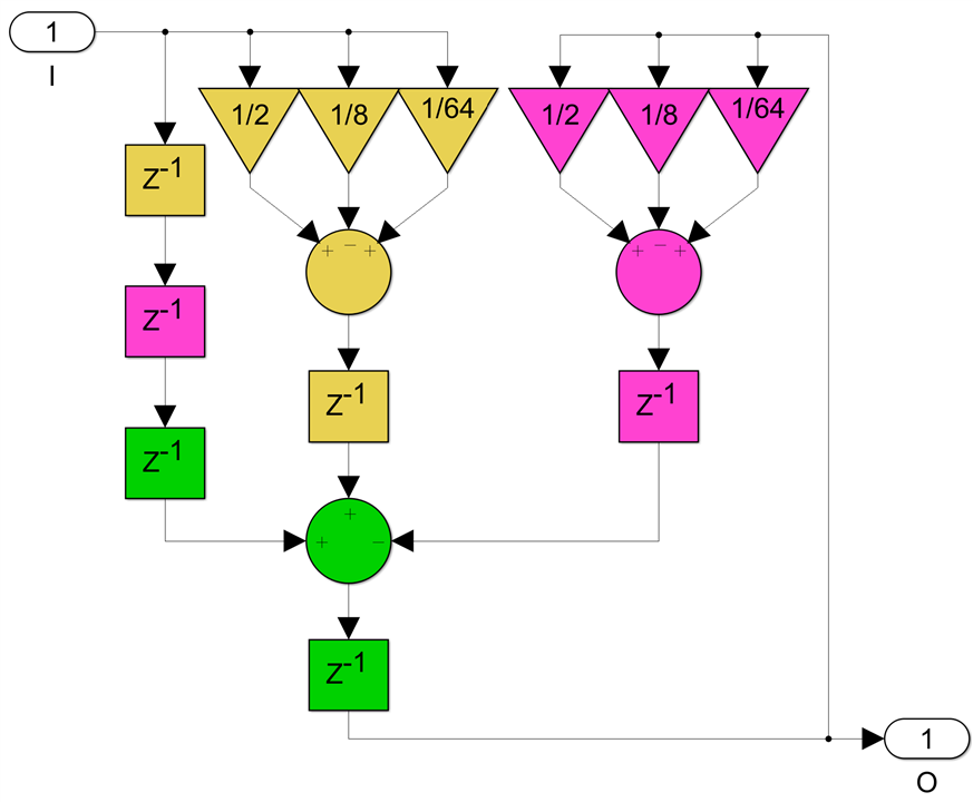
The 3 non-zero bits case, for example c=25/64:
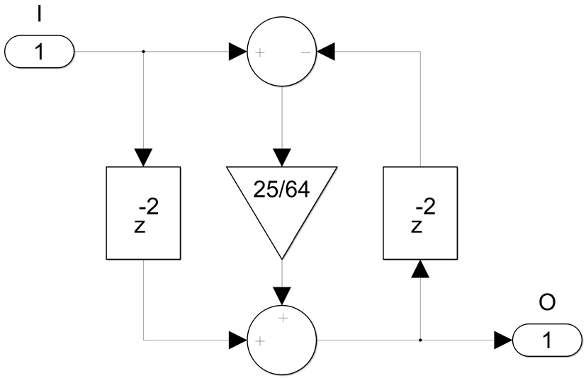
can be done with three 3-input adders:
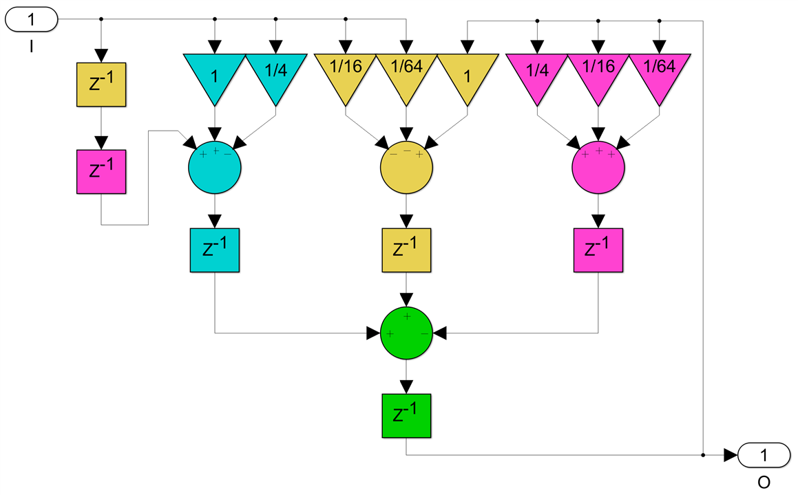
Finally, the 4 non-zero bit coefficients like c=43/64:
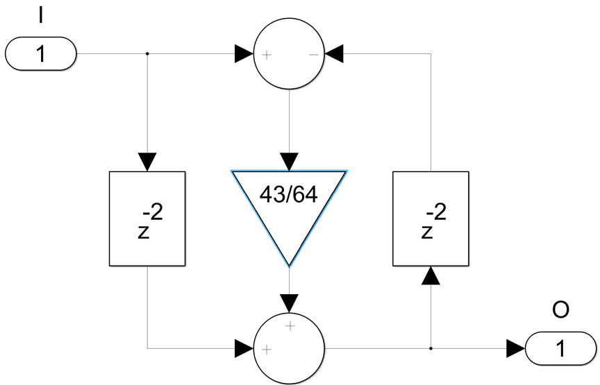
will require four 3-input adders:
The 2, 3 and 4 non-zero bit cases can be pipelined with just two register levels, so they can achieve sample rates equal to half the clock rate, compared with a quarter clock rate when DSP primitives are used.
So there are significant benefits to these multiplierless schemes but how practical are they? When you design for a certain filter transfer function and then aggressively quantize the coefficients to achieve these 2, 3 or 4 non-zero bit values you get a different filter. Fortunately, LWDF IIRs, similar to FIR filters have almost all their coefficient sensitivity concentrated in the stop band. When you quantize the coefficients the pass band will change very little while the stop band can change a lot. This happens to work very well with the trick of designing for the square root of the filter you actually need and then cascading two such instances. This makes it easier to achieve both very little passband ripple and high stop band attenuation while aggressively quantizing the coefficients.
Add on top of that the doubling in the maximum achievable sample rate and the savings in DSP primitives utilization and this becomes a very interesting design solution.
I will end this series on LWDF IIR filters with a final post considering more advanced techniques of pipelining such filters to achieve higher sample rates.
Back to the top: The Art of FPGA Design Season 2

