Introduction
This project is part 1 of a 5 part series of projects, where we will progressively create AI enabled platforms for the following Tria development boards:
- ZUBoard
- Ultra96-V2
- UltraZed-7EV
These projects can be rebuilt using the source code on github.com:
The following series of Hackster projects describe how the above github repository was created and serves as documentation:
- Part 1 : Tria Vitis Platforms - Building the Foundational Designs
- Part 2 : Tria Vitis Platforms - Creating a Common Platform
- Part 3 : Tria Vitis Platforms - Adding support for Vitis-AI
- Part 4 : Tria Vitis Platforms - Adding support for Hailo-8
- Part 5 : Tria Vitis Platforms - Adding support for ROS2
The motivation of this series of projects is to enable users to create their own custom AI applications.
Introduction - Part I
Every time Tria Technologies releases a new petalinux BSP version for its platforms, it's like Christmas.
I always start my designs from these BSPs, which include both hardware (Vivado) and software (Petalinux) components.
Foundational Design Overview
I call these projects the foundational designs, since they are literally the foundation on which I create more advanced projects, including hardware accelerators and additional software packages.
The foundational designs have the following naming scheme:
- {hwcore}_{hwtype}_{design}
The {hwcore} refers to one of the target hardware, which are covered by this project:
- zub1cg : ZUBoard development board
- u96v2 : Ultra96-V2 development board
- uz7ev : UltraZed-7EV SOM
The {hwtype} will be either sbc (single-board computer) for development boards, or a designator for the carrier card, such as
- evcc : UltraZed-EV carrier card
To summarize, the following hardware targets will be covered by this project:
- zub1cg_sbc
- u96v2_sbc
- uz7ev_evcc
Although more designs exist, I will covering the following designs for each hardware target:
- u96v2_sbc : base, dualcam
- zub1cg_sbc : base, trifecta
- uz7ev_evcc : base, nvme
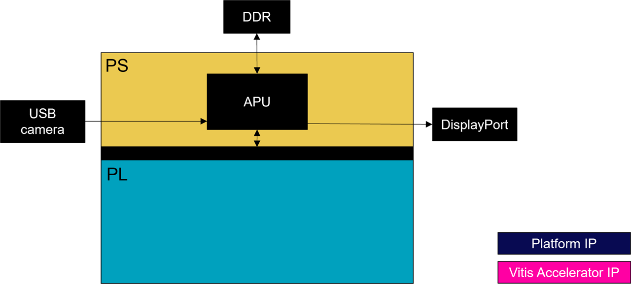
The Base Designs
The first designs, the base designs, are the simplest design. They have their PL (almost) empty.
The DualCam Designs
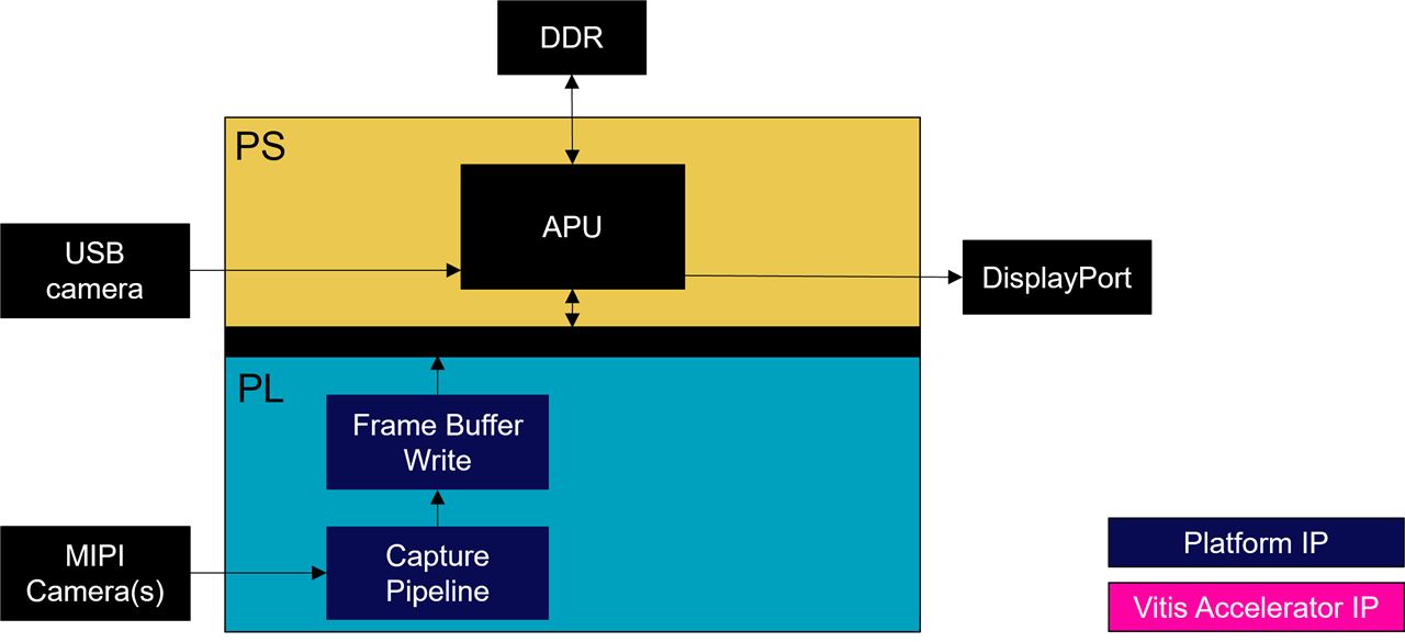
The second designs, the dualcam and trifecta designs, implements a MIPI capture pipeline in the PL (hardware), and supports the V4L2 API in linux (software).
Designs augmented with PCIe functionnality
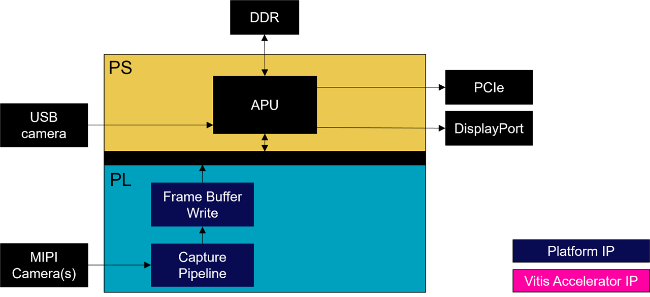
Note that for the ZUBoard, there are two dualcam designs : zub1cg_sbc_dualcam and zub1cg_sbc_trifecta.
The zub1cg_sbc_trifecta design augments the dualcam design with PCIe functionality via the M.2 HSIO module.
Similarly, the uz7ev_evcc_nvme design augments the base design with PCIe functionality available via Opsero's FMC M.2 M-Key Stack FMC.
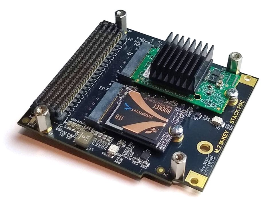
- [Opsero] M.2 M-key Stack FMC
The next sections describe how to rebuild these foundational designs from source in the Avnet github repositories.
Cloning the Avnet github repositories
Tria Technologies is an Avnet owned company, that used to be part of Avnet. For this historical reason, the github repositories are still under the "Avnet" brand.
The foundational designs make use of the following Avnet github repositories:
- github.com/Avnet/bdf (latest branch)
- github.com/Avnet/hdl (2023.2 branch)
- github.com/Avnet/petalinux (2023.2 branch)
- github.com/Avnet/meta-avnet (2023.2 branch)
- github.com/Avnet/meta-on-semiconductor (2023.2 branch)
The first thing to do is to clone the three (3) first repositories to a Ubuntu linux machine which has the 2023.2 tools installed. I like to do this in a directory that has a meaningful name (such as "Avnet_2023_2" in my root directory):
$ cd ~
$ mkdir Avnet_2023_2
$ cd ~/Avnet_2023_2
$ git clone https://github.com/Avnet/bdf
$ git clone -b 2023.2 https://github.com/Avnet/hdl
$ git clone -b 2023.2 https://github.com/Avnet/petalinux
The last two repositories will get cloned during the build process, so no need to clone them.
Building the designs
This sections applies to all the designs, {hwcore}_{hwtype}_{design}, including:
- u96v2_sbc_base | u96v2_sbc_dualcam
- zub1cg_sbc_base | zub1cg_sbc_trifecta
- uz7ev_evcc_base | uz7ev_evcc_nvme
Prior to building any of the designs, first call your 2023.2 setup scripts:
$ source /tools/Xilinx/Vitis/2023.2/settings64.sh

$ source /tools/Xilinx/petalinux-v2023.2-final/settings.sh
Next, launch the petalinux build script as follows:
$ cd ~/Avnet_2023_2/petalinux
$ scripts/make_{hwcore}_{hwtype}_{design}.sh
This script will perform the following:
- Create and Build the Vivado project
~/Avnet_2023_2/hdl/projects/{hwcore}_{hwtype}_{design}_2023_2 Create and Build the Petalinux project ~/Avnet_2023_2/petalinux/projects/{hwcore}_{hwtype}_{design}_2023_2Create a final SD card image ~/Avnet_2023_2/petalinux/projects/{hwcore}_{hwtype}_{design}_2023_2/images/linux/rootfs.wic
re-Enabling the Cache
It is important to know that the automated petalinux build configured the petalinux project to cache all the packages that are fetched from the internet. That way, those packages are only fetched once for all the petalinux projects, and reused from the local cache.
If your automated build succeeded, the cache will have been disabled in the petalinux project. You "may" want to re-enable it by editing the following files:
project-spec/configs/config
...

#
# Add pre-mirror URL
#
CONFIG_PRE_MIRROR_URL="file://{path}/Avnet_2023_2/petalinux/projects/cache/downloads_2023.2/"

...

#
# Network sstate feeds URL
#
CONFIG_YOCTO_LOCAL_SSTATE_FEEDS_URL="file://{path}/Avnet_2023_2/petalinux/projects/cache/sstate_2023.2/aarch64/"
CONFIG_NETWORK_LOCAL_SSTATE_FEEDS=y

...
project-spec/meta-user/conf/petalinuxbsp.conf
...

PREMIRRORS:prepend = "git://.*/.* file://{path}/Avnet_2023_2/petalinux/projects/cache/downloads_2023.2/ \
ftp://.*/.* file://{path}/Avnet_2023_2/petalinux/projects/cache/downloads_2023.2/ \
http://.*/.* file://{path}/Avnet_2023_2/petalinux/projects/cache/downloads_2023.2/ \
https://.*/.* file://{path}/Avnet_2023_2/petalinux/projects/cache/downloads_2023.2/ "

DL_DIR="{path}/Avnet_2023_2/petalinux/projects/cache/downloads_2023.2/"
SSTATE_DIR"{path}/Avnet_2023_2/petalinux/projects/cache/sstate_2023.2/"

...
where {path} is the absolute path to your Avnet_2023_2 directory.
Booting the "base" designs
In order to execute the base design, we first need to program the SD card image to a micro-SD card (of size 32GB or greater).
~/Avnet_2023_2/petalinux/projects/{hwcore}_{hwtype}_{design}_2023_2/images/linux/rootfs.wic
The {hwcore}_{hwtype}_{design} will correspond to the following for each platform:
- ZUBoard : zub1cg_sbc_base
- Ultra96-V2 : u96v2_sbc_base
- UltraZed-EV : uz7ev_evcc_base
To do this, we use Balena Etcher, which is available for most operating systems.
With the base design programmed to micro-SD card, refer to the following sections on how to setup the hardware platform and boot the embedded linux.
Setting up the ZUBoard Hardware
The ZUBoard hardware should be setup as shown below:
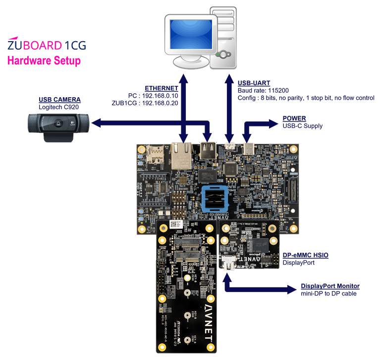
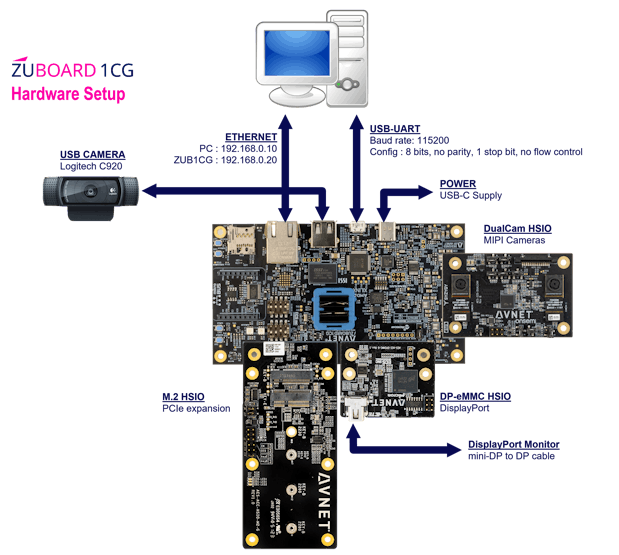
If you have the DualCam HSIO module, make sure that its jumpers are configured as follows:
- J1 => HSIO
- J2 => MIPI DSI
- J3 – present => VAA connected
- J4/J14 – J4.1-J4.2 => VDD is 1.2V (This needs to be set to 1-2 for 2.8V)
- J5 – 2-3 => Clock is on-board OSC(48 MHz)
- J6 => IAS0
- J7 => IAS1
- J8 – 2-3 => SENSOR1_GPIO1 is 1V8_SP2
- J9 – 2-3 => SENSOR1_GPIO3 is GND
- J10 – 2-3 => SENSOR2_GPIO1 is 1V8_SP3
- J11 – 2-3 => SENSOR2_GPIO3 is SENS2_ADDR
- J12 – absent => SENSOR1_GPIO0/FLASH
- J13 – absent => SENSOR2_GPIO0/FLASH
- J15 => MCU PROG
If you have the M.2 HSIO module, make sure its jumpers are configured as follows:
- J19 – present => M.2 switch configured for B-Key (supporting B+M Key modules)
Once the hardware setup is ready, press the power push-button.
As linux boots, a large quantity of verbose output will be sent to the serial console, ending with a login prompt:
...

zub1cg-sbc-base-2023-2 login:
If not done so already, login as the "root" user as follows:
zub1cg-sbc-base-2023-2 login: root

root@zub1cg-sbc-base-2023-2:~#
Setting up the Ultra96-V2 Hardware
The Ultra96-V2 hardware should be setup as shown below:
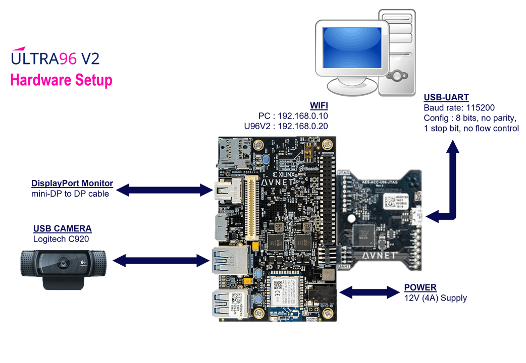
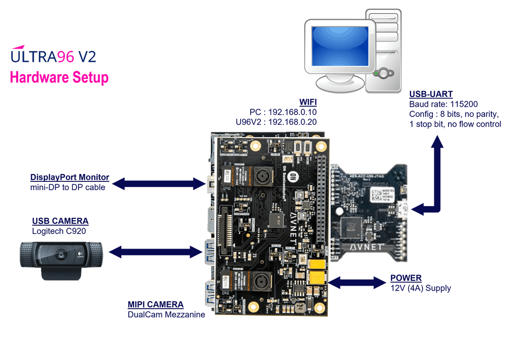
If you have the DualCam mezzanine, make sure it has the jumpers configured as follows:
- J1 => IAS0
- J2 => IAS1
- J3 => 96Boards High-Speed Connector
- J4 => 96Boards Low-Speed Connector
- J5 => MIPI DSI
- P1 – 1-2 => SENSOR1_GPIO1 is +2V8_AF
- P2 – 2-3 => SENSOR2_GPIO1 is 96B_SP3
- P3 – present => SENSOR1_GPIO0/FLASH is GND
- P4 – present => SENSOR2_GPIO0/FLASH is GND
- P5 – 2-3 => SENSOR1_GPIO3 is GND
- P6 – 2-3 => SENSOR2_GPIO3 is SENS2_ADDR
- P7 – 1-2 => PWR_SEL is 5V
- P8-P9 – P8.2-P8.3 => VDD_SEL is 1.2V
- P10 – 1-2 => VAA_SEL is 2.7V (3-2 => 2.8V)
- P11 – 2-3 => CLK_SEL is on-board OSC(48 MHz)
Once the hardware setup is ready, press the power push-button.
As linux boots, a large quantity of verbose output will be sent to the serial console, ending with a login prompt:
...

u96v2-sbc-base-2023-2 login:
If not done so already, login as the "root" user as follows:
u96v2-sbc-base-2023-2 login: root

root@u96v2-sbc-base-2023-2:~#
We will be using a DisplayPort monitor to view video output from the Ultra96-V2. You should observe the matchbox desktop on the DisplayPort monitor.

With a USB keyboard & mouse, click on "Connman Settings" to configure the WIFI.

Click on "Wireless", then select your WIFI network, and specify your passphrase.
Once the WIFI is connected, you can discover which IP address has been assigned to your Ultra96-V2 with the following command:
root@u96v2-sbc-base-2023-2:~# ifconfig -a wlan0
wlan0     Link encap:Ethernet  HWaddr F8:F0:05:C4:17:66
          inet addr:10.0.0.179  Bcast:10.0.0.255  Mask:255.255.255.0
          inet6 addr: fe80::faf0:5ff:fec4:1766/64 Scope:Link
          UP BROADCAST RUNNING MULTICAST  MTU:1500  Metric:1
          RX packets:61 errors:0 dropped:0 overruns:0 frame:0
          TX packets:79 errors:0 dropped:0 overruns:0 carrier:0
          collisions:0 txqueuelen:1000
          RX bytes:7330 (7.1 KiB)  TX bytes:12263 (11.9 KiB)

root@u96v2-sbc-base-2023-2:~#
Setting up the UltraZed-EV Hardware
The UltraZed-EV hardware should be setup as shown below:
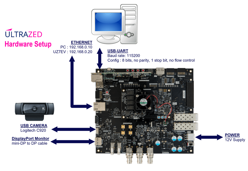
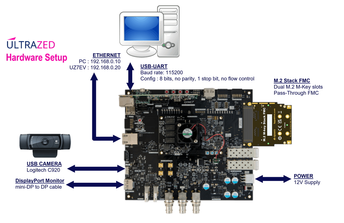
Once the hardware setup is ready, slide the power switch to the "on" position.
As linux boots, a large quantity of verbose output will be sent to the serial console, ending with a login prompt:
...

uz7ev-evcc-base-2023-2 login:
If not done so already, login as the "root" user as follows:
uz7ev-evcc-base-2023-2 login: root

root@uz7ev-evcc-base-2023-2:~#
Exploring the "base" designs
If not done so already, login as the "root" user as follows:
{hwcore}_{hwtype}-{design}-2023-2 login: root

root@{hwcore}_{hwtype}-{design}-2023-2:~#
Next we can perform a quick sanity check with the USB camera.
We can query the presence of the USB camera with the following commands:
root@{hwcore}_{hwtype}-{design}-2023-2:~# v4l2-ctl --list-devices
UVC Camera (046d:0825) (usb-xhci-hcd.1.auto-1):
        /dev/video0
        /dev/video1
        /dev/media0

root@{hwcore}_{hwtype}-{design}-2023-2:~# media-ctl -p -d /dev/media0
Media controller API version 5.15.36

Media device information
------------------------
driver          uvcvideo
model           UVC Camera (046d:0825)
serial          33E07BA0
bus info        usb-xhci-hcd.2.auto-1
hw revision     0x12
driver version  5.15.36

Device topology
...

root@{hwcore}_{hwtype}-{design}-2023-2:~# v4l2-ctl -D -d /dev/video0
Driver Info:
        Driver name      : uvcvideo
        Card type        : UVC Camera (046d:0825)
        Bus info         : usb-xhci-hcd.2.auto-1
        Driver version   : 5.15.36
        Capabilities     : 0x84a00001
                Video Capture
                Metadata Capture
                Streaming
                Extended Pix Format
                Device Capabilities
        Device Caps      : 0x04200001
                Video Capture
                Streaming
                Extended Pix Format
...

root@{hwcore}_{hwtype}-{design}-2023-2:~# v4l2-ctl -D -d /dev/video1
Driver Info:
        Driver name      : uvcvideo
        Card type        : UVC Camera (046d:0825)
        Bus info         : usb-xhci-hcd.2.auto-1
        Driver version   : 5.15.36
        Capabilities     : 0x84a00001
                Video Capture
                Metadata Capture
                Streaming
                Extended Pix Format
                Device Capabilities
        Device Caps      : 0x04a00000
                Metadata Capture
                Streaming
                Extended Pix Format
...
We observe that one media node (/dev/media0) and two video nodes (/dev/video0, /dev/video1) have been enumerated.
Inspecting the "Device Caps" of each video node, we take note that the /dev/video0 is the one which has "Video Capture" capability.
Create a new python script in the root directory with the following content:
import cv2

# Open the camera
cap = cv2.VideoCapture(0)

# Set the resolution
cap.set(cv2.CAP_PROP_FRAME_WIDTH, 640)
cap.set(cv2.CAP_PROP_FRAME_HEIGHT, 480)

# Create a display window
cv2.namedWindow("USB Cam Passthrough", cv2.WINDOW_NORMAL)

while True:
    # Read a frame from the camera
    ret, frame = cap.read()

    if ret:
        # Display the frame in the window
        cv2.imshow("USB Cam Passthrough", frame)

    # Check for key presses
    key = cv2.waitKey(1)
    if key == 27:   # Pressing the Esc key exits the program
        break

# Release the camera and destroy the display window
cap.release()
cv2.destroyAllWindows()
NOTE : This code was generated by ChatGPT with the following prompt : "python code usbcam passthrough 640x480"
Run this script from a desktop terminal as follows:
root@{hwcore}_{hwtype}-{design}-2023-2:~# python3 usbcam_passthrough.pyThis will display the video from the USB camera in a window on the embeded desktop running on the DisplayPort display.

Exploring the "dualcam" designs
In order to execute the dualcam designs, we first need to program the SD card image to a micro-SD card (of size 32GB or greater).
~/Avnet_2023_2/petalinux/projects/{hwcore}_{hwtype}-{design}_2023_2/images/linux/rootfs.wic
The {hwcore}_{hwtype}-{design} will correspond to the following for each platform:
- ZUBoard : zub1cg_sbc_trifecta
- Ultra96-V2 : u96v2_sbc_dualcam
Once programmed, and inserted into the target board, press the power push-button to boot the board, and login as "root".
Next we can perform a quick sanity check with the dual MIPI sensor module.
We can query the presence of the MIPI sensors with the following commands:
root@{hwcore}_{hwtype}-{design}-2023-2:~# v4l2-ctl --list-devices
Xilinx Video Composite Device (platform:axi:vcap_CAPTURE_PIPEL):
        /dev/media1

vcap_CAPTURE_PIPELINE_v_proc_ss (platform:vcap_CAPTURE_PIPELINE_):
        /dev/video2

UVC Camera (046d:0825) (usb-xhci-hcd.1.auto-1):
        /dev/video0
        /dev/video1
        /dev/media0

root@{hwcore}_{hwtype}-{design}-2023-2:~#
Note that the USB camera has still been enumerated as media node /dev/media0 and video nodes /dev/video0 and /dev/video1. The dual MIPI capture pipeline has been enumerated at the next available nodes, which are /dev/media1 and /dev/video2. If the USB camera were not plugged in, the MIPI capture pipeline would have been enumerated as /dev/media0 and /dev/video0.
root@{hwcore}_{hwtype}-{design}-2023-2:~# media-ctl -p -d /dev/media1
Media controller API version 6.1.30

Media device information
------------------------
driver          xilinx-video
model           Xilinx Video Composite Device
serial
bus info        platform:axi:vcap_CAPTURE_PIPEL
hw revision     0x0
driver version  6.1.30

Device topology
- entity 1: vcap_CAPTURE_PIPELINE_v_proc_ss (1 pad, 1 link)
            type Node subtype V4L flags 0
            device node name /dev/video2
        pad0: Sink
                <- "b0040000.v_proc_ss":1 [ENABLED]

- entity 5: b0000000.mipi_csi2_rx_subsystem (2 pads, 2 links)
            type V4L2 subdev subtype Unknown flags 0
            device node name /dev/v4l-subdev0
        pad0: Sink
                [fmt:UYVY8_1X16/1920x1080 field:none colorspace:srgb]
                <- "ap1302.0-003c":2 [ENABLED]
        pad1: Source
                [fmt:UYVY8_1X16/1920x1080 field:none colorspace:srgb]
                -> "b0020000.v_proc_ss":0 [ENABLED]

- entity 8: ap1302.0-003c (6 pads, 3 links)
            type V4L2 subdev subtype Sensor flags 0
            device node name /dev/v4l-subdev3
        pad0: Sink
                [fmt:SGRBG12_1X12/1280x800 field:none colorspace:srgb
                 crop.bounds:(0,0)/2560x800
                 crop:(0,0)/2560x800]
                <- "0-003c.ar0144.0":0 [ENABLED]
        pad1: Sink
                [fmt:SGRBG12_1X12/1280x800 field:none colorspace:srgb
                 crop.bounds:(0,0)/2560x800
                 crop:(0,0)/2560x800]
                <- "0-003c.ar0144.1":0 [ENABLED]
        pad2: Source
                [fmt:UYVY8_1X16/1280x800 field:none colorspace:srgb
                 crop.bounds:(0,0)/2560x800
                 crop:(0,0)/2560x800]
                -> "b0000000.mipi_csi2_rx_subsystem":0 [ENABLED]
        pad3: Source
                [fmt:UYVY8_1X16/1280x800 field:none colorspace:srgb
                 crop.bounds:(0,0)/2560x800
                 crop:(0,0)/2560x800]
        pad4: Source
                [fmt:UYVY8_1X16/1280x800 field:none colorspace:srgb
                 crop.bounds:(0,0)/2560x800
                 crop:(0,0)/2560x800]
        pad5: Source
                [fmt:UYVY8_1X16/1280x800 field:none colorspace:srgb
                 crop.bounds:(0,0)/2560x800
                 crop:(0,0)/2560x800]

- entity 15: 0-003c.ar0144.0 (1 pad, 1 link)
             type V4L2 subdev subtype Sensor flags 0
             device node name /dev/v4l-subdev1
        pad0: Source
                [fmt:SGRBG12_1X12/1280x800 field:none colorspace:srgb]
                -> "ap1302.0-003c":0 [ENABLED]

- entity 19: 0-003c.ar0144.1 (1 pad, 1 link)
             type V4L2 subdev subtype Sensor flags 0
             device node name /dev/v4l-subdev2
        pad0: Source
                [fmt:SGRBG12_1X12/1280x800 field:none colorspace:srgb]
                -> "ap1302.0-003c":1 [ENABLED]

- entity 23: b0020000.v_proc_ss (2 pads, 2 links)
             type V4L2 subdev subtype Unknown flags 0
             device node name /dev/v4l-subdev4
        pad0: Sink
                [fmt:UYVY8_1X16/1280x720 field:none colorspace:rec709]
                <- "b0000000.mipi_csi2_rx_subsystem":1 [ENABLED]
        pad1: Source
                [fmt:UYVY8_1X16/1280x720 field:none colorspace:rec709]
                -> "b0040000.v_proc_ss":0 [ENABLED]

- entity 26: b0040000.v_proc_ss (2 pads, 2 links)
             type V4L2 subdev subtype Unknown flags 0
             device node name /dev/v4l-subdev5
        pad0: Sink
                [fmt:UYVY8_1X16/1280x720 field:none colorspace:srgb]
                <- "b0020000.v_proc_ss":1 [ENABLED]
        pad1: Source
                [fmt:UYVY8_1X16/1920x1080 field:none colorspace:srgb]
                -> "vcap_CAPTURE_PIPELINE_v_proc_ss":0 [ENABLED]


root@{hwcore}_{hwtype}-{design}-2023-2:~# v4l2-ctl -D -d /dev/video2
Driver Info:
        Driver name      : xilinx-vipp
        Card type        : vcap_CAPTURE_PIPELINE_v_proc_ss
        Bus info         : platform:vcap_CAPTURE_PIPELINE_
        Driver version   : 6.1.30
        Capabilities     : 0x84201000
                Video Capture Multiplanar
                Streaming
                Extended Pix Format
                Device Capabilities
        Device Caps      : 0x04201000
                Video Capture Multiplanar
                Streaming
                Extended Pix Format
By default, the petalinux project is configured for the AR0144 sensors, which are the sensor modules that are shipped with the DualCam add-on modules.
root@{hwcore}_{hwtype}-{design}-2023-2:~# media-ctl -p -d /dev/media1 | grep ar
                <- "0-003c.ar0144.0":0 [ENABLED]
                <- "0-003c.ar0144.1":0 [ENABLED]
- entity 15: 0-003c.ar0144.0 (1 pad, 1 link)
- entity 19: 0-003c.ar0144.1 (1 pad, 1 link)
The petalinux project also provides some python scripts to configure the MIPI capture pipeline and stream the video via GStreamer and OpenCV. Launch the "avnet_dualcam_passthrough.py" python script from the serial console as follows:
root@{hwcore}_{hwtype}-{design}-2023-2:~# cd ~/avnet_dualcam_python_examples/

root@{hwcore}_{hwtype}-{design}-2023-2:~/avnet_dualcam_python_examples# export DISPLAY=:0.0

root@{hwcore}_{hwtype}-{design}-2023-2:~/avnet_dualcam_python_examples# python3 avnet_dualcam_passthrough.py --sensor ar0144 --mode dual
[INFO] input resolution =  640 X 480
[INFO] fps overlay =   False
[INFO] brightness =  256
[INFO] Initializing the capture pipeline ...

[DualCam] Looking for devices corresponding to AP1302
        dev_video =  /dev/video2
        dev_media =  /dev/media1
        sensor_type =  ar0144
        ap1302_i2c =  4-003c
        ap1302_dev =  ap1302.4-003c
        ap1302_sensor =  4-003c.ar0144

[DualCam] Looking for base address for MIPI capture pipeline
        mipi_desc =  b0000000.mipi_csi2_rx_subsystem
        csc_desc =  b0020000.v_proc_ss
        scaler_desc =  b0040000.v_proc_ss

[DualCam] hostname =  {hwcore}

[DualCam] Detected 96Boards dualcam (sensors placed right-left on board)

[DualCam] Initializing AP1302 for dual sensors
media-ctl -d /dev/media1 -l '"4-003c.ar0144.0":0 -> "ap1302.4-003c":0[1]'
media-ctl -d /dev/media1 -l '"4-003c.ar0144.1":0 -> "ap1302.4-003c":1[1]'

[DualCam] Initializing capture pipeline for  ar0144 dual 640 480
media-ctl -d /dev/media1 -V "'ap1302.4-003c':2 [fmt:UYVY8_1X16/2560x800 field:none]"
media-ctl -d /dev/media1 -V "'b0000000.mipi_csi2_rx_subsystem':0 [fmt:UYVY8_1X16/2560x800 field:none]"
media-ctl -d /dev/media1 -V "'b0000000.mipi_csi2_rx_subsystem':1 [fmt:UYVY8_1X16/2560x800 field:none]"
media-ctl -d /dev/media1 -V "'b0020000.v_proc_ss':0 [fmt:UYVY8_1X16/2560x800 field:none]"
media-ctl -d /dev/media1 -V "'b0020000.v_proc_ss':1 [fmt:RBG24/2560x800 field:none]"
media-ctl -d /dev/media1 -V "'b0040000.v_proc_ss':0 [fmt:RBG24/2560x800 field:none]"
media-ctl -d /dev/media1 -V "'b0040000.v_proc_ss':1 [fmt:RBG24/1280x480 field:none]"

[DualCam] Disabling Auto White Balance
v4l2-ctl --set-ctrl white_balance_auto_preset=0 -d /dev/video2

[DualCam] Opening cv2.VideoCapture for  1280 480
GStreamer pipeline = v4l2src device=/dev/video2 io-mode="dmabuf" ! video/x-raw, width=1280, height=480, format=BGR, framerate=60/1 ! appsink
[ WARN:0] global /usr/src/debug/opencv/4.5.2-r0/git/modules/videoio/src/cap_gstreamer.cpp (1081) open OpenCV | GStreamer warning: Cannot query video position: status=0, value=-1, duration=-1


[DualCam] Setting brightness to  256
v4l2-ctl --set-ctrl brightness=256 -d /dev/video2
This will display the stereo video from the dual MIPI capture pipeline in a window on the DisplayPort output.
The "media-ctl" and "v4l2-ctl" commands configure the following MIPI capture pipeline.

The "dual" mode captures the stereo images as shown in the following diagram.
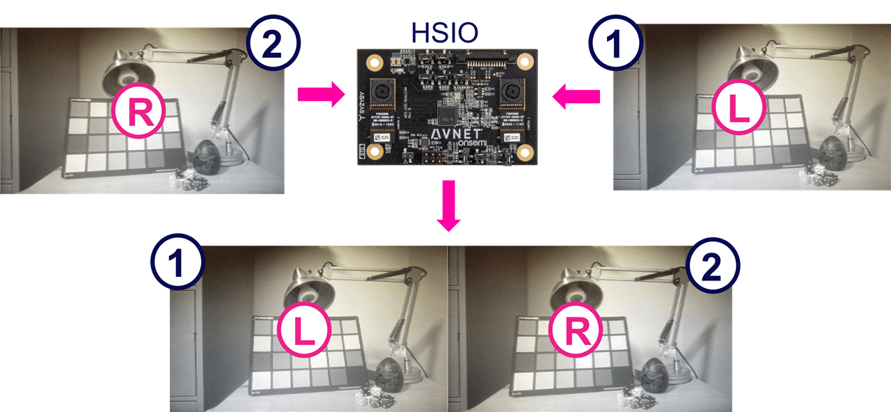
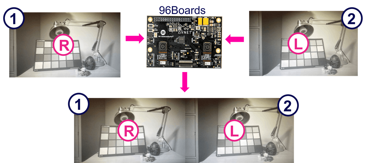
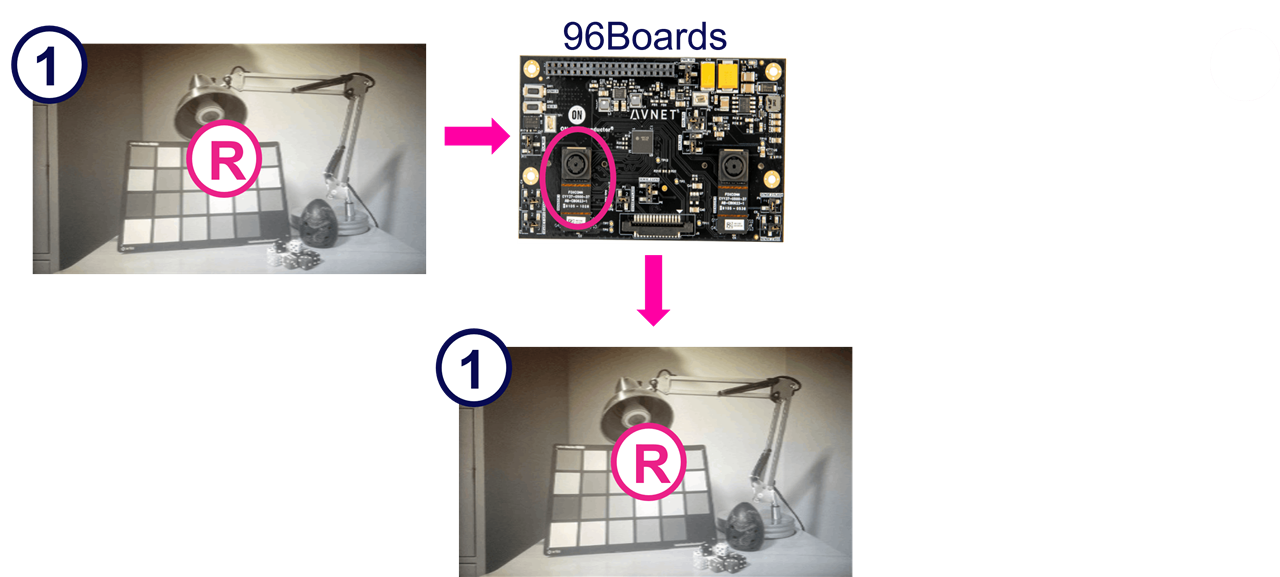
Note that for the ZUBoard, the primary sensor (1) corresponds to the left (L) image, and the secondary sensor (2) corresponds to the right (R) image.
For the Ultra96-V2, however, this is inversed. The primary sensor (1) corresponds to the right image, and the secondary sensor (2) corresponds to the left image.
You can also stream video from the primary (right) sensor as follows:
root@{hwcore}_{hwtype}-{design}-2023-2:~/avnet_dualcam_python_examples# python3 avnet_dualcam_passthrough.py --sensor ar0144 --mode primary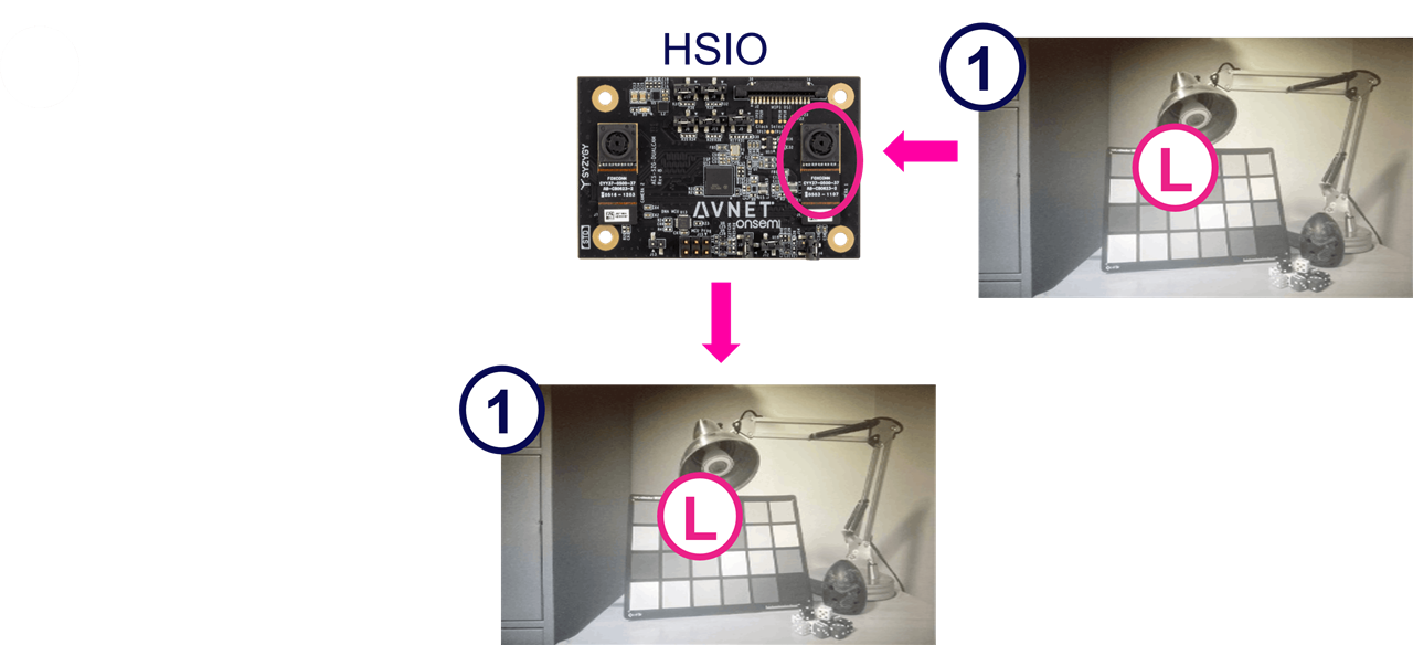
You can also stream video from the secondary (left) sensor as follows:
root@{hwcore}_{hwtype}-{design}-2023-2:~/avnet_dualcam_python_examples# python3 avnet_dualcam_passthrough.py --sensor ar0144 --mode secondary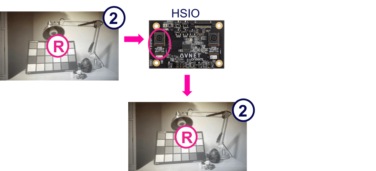
Acknowledgements
I want to thank Jeff Johnson (Opsero) for his M.2 M-Key Stack FMC, allowing further expansion of the UltraZed-7EV FMC Carrier Card, with M.2 M-Key modules:
- [Opsero] M.2 M-key Stack FMC
Conclusion
I hope this tutorial will help you to get your custom AI applications up and running quickly on the Tria development boards.
If you would like to have the pre-built petalinux BSPs or SDcard images for these designs, please let me know in the comments below.
Revision History
2024/10/28 - Preliminary Version


-

jensi
-
Cancel
-
Vote Up
0
Vote Down
-
-
Sign in to reply
-
More
-
Cancel
Comment-

jensi
-
Cancel
-
Vote Up
0
Vote Down
-
-
Sign in to reply
-
More
-
Cancel
Children