Introduction:
The Arty S7 board comes with an on board ADC. The XADC core within the Spartan-7 is a dual channel 12-bit analog-to-digital converter capable of operating at 1 MSPS. The analog pins can be used to read analog values. I have a IR sensor which I had pulled out of a DVD player sometime ago.
In this blog, I will try to interface this IR sensor using the XADC block on the FPGA board.
Creating the block design:
I will be using the block design that I created earlier for MicroBlaze based Microcontroller. You can visit this blog to know more. The block design is shown below:
Now, to this block design we need to add the xadc IP.
- Click on "Add IP" and insert the "XADC Wizard".
- Double Click on it to customize it.
- Select AXI4Lite for "Interface Options" and Channel Sequencer for "Startup Channel Selection".
- In the Channel Sequencer tab, select vauxp0/vauxn0 (You can also select other channels if you wish to).
- Click on OK.
- Run connection automation by selecting all automation.
- Regenerate the layout. The block design should look like this:
- Now, right click on "Vp_Vn" port of the XADC block and click on "Create Interface Port". Click on OK.
- Now, right click on "Vaux0" port of the XADC block and click on "Create Interface Port". Click on OK.
- Regenerate the layout. The final block design should look like this:
- Validate the design and create HDL wrapper.
- Now, we have to include a constraint file to define proper IOStandard for our XADC. I ran into some error saying "IOStandards not compatible" while trying to implement my design without the constraint file. But after including the constraint file, it worked fine.
- Download the constraint file for the Arty S7-50 board from this link. Copy the contents and paste it in a new constraint file created in the Vivado project.
- Uncomment some lines as shown below:
- We are using only one port, so we need to uncomment lines corresponding to that port only.
- We will have to change the port name as shown in the image otherwise it will show errors.
Now, save the changes to the constraint file, generate bitstream and export it.
Hardware Setup:
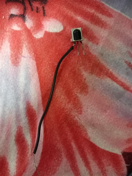
I am using a three terminal IR receiver and my TV remote as an IR trasmitter. I had pulled out the IR receiver from a DVD player. I broke one of its leg by mistake, so I have soldered a wire to it.

- The leftmost terminal is the output through which we can sense the change in voltage caused by IR.
- The middle terminal is Ground.
- The rightmost terminal is the supply. I am supplying it with the 3V3 pin on the board.
Working on Vitis:
Now, open vitis, select the wrapper file (xsa file) that we earlier generated as platform and create an empty C application project. Inside the "src" folder create a "main.c" source file and copy the "platform.h", "platform.c" and "platform_config.h" from the "Hello World" template project's "src" folder. You should have all the files in the "src" folder as shown below:
Inside the "main.c" file, paste the following code:
#include <xparameters.h>
#include <xil_types.h>
#include <xsysmon.h>
#include <sleep.h>
#include <xil_printf.h>
#include "platform.h"

//XADC and XADC Config Instances
XSysMon xadc;
XSysMon_Config *xadc_config;

int main() {
	init_platform();

	//Variable to store the input
	u16 aux;

	//Load default configuration and initialize the XADC
	xadc_config = XSysMon_LookupConfig(XPAR_SYSMON_0_DEVICE_ID);
	XSysMon_CfgInitialize(&xadc, xadc_config, xadc_config->BaseAddress);

	while(1) {
		//Get the analog data from channel 16 i.e. A0 on the board
		aux = XSysMon_GetAdcData(&xadc, XSM_CH_AUX_MIN);
		xil_printf("%d ", aux);

		//Convert the raw input into voltage value
		aux = XSysMon_RawToVoltage(aux);
		xil_printf("%d || ", aux);

		//Wait for 0.2 sec before next iteration
		usleep(200000);
	}

	cleanup_platform();
	return 0;
}
You can explore the "xsysmon.h" header file to learn about more functions.
Build the code, Program the FPGA and run the code on the hardware.
I opened a serial monitor on Putty to monitor the value of the "aux" variable. A screenshot of the serial terminal is shown below:
As, it can be seen in the image (circled areas), the value of the aux variable drops to some value below 500 whenever I press any key on the remote or the IR receiver receives any IR signal.
Conclusion:
The XADC delivers advantages in flexibility, integration, and cost savings across a wide range of applications. In addition to performing system monitoring functions, the XADC can directly replace discrete analog-to-digital converters required in many applications, e.g. Motor Control and Power Conversion. By adding an IR sensor, I can implement remote control functionality in my design.
