


The Xilinx Zynq UltraScale+ MPSoC device has an integrated Platform Management Unit or PMU. This PMU's functionality is described in Chapter 6 of Xilinx UG1085, Zynq UltraScale+ Device Technical Reference Manual. The PMU controls many things on the ZU+ device, including powering up and down the ZU+. The Ultra96-V2 incorporates an On/Off controller to interface between the on-board power regulators and the ZU+. This allows the ZU+, Power Button, and regulators to seamlessly work together to power the system on and off without corrupting your Linux (or other OS) file system.
The key inputs/outputs of the system are detailed below:
| Signal Name | Source | Destination | Polarity | Description |
|---|---|---|---|---|
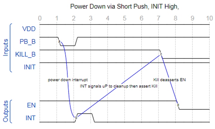
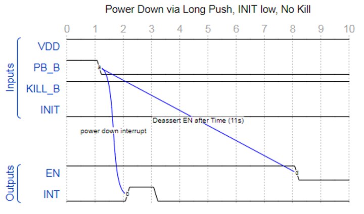
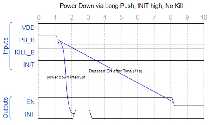
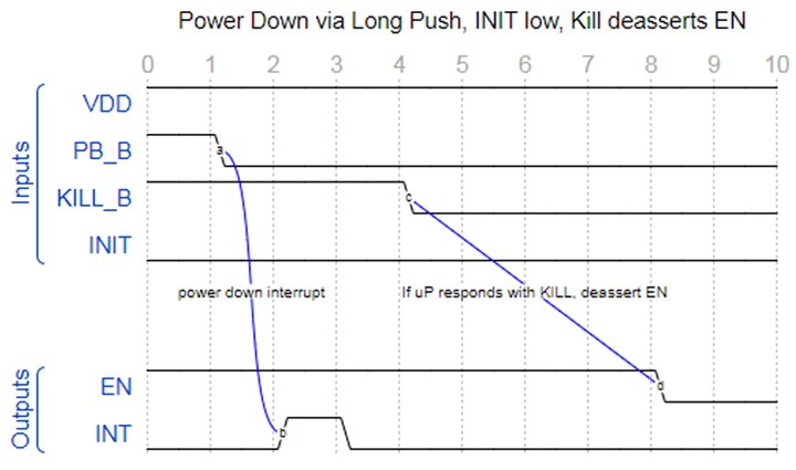
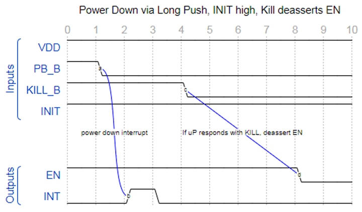
| PWR_PB_N | Push Button (SW4) | On/Off Controller (U6) | Low-enabled | Push button input for powering on and off. Responds to both short and long pushes. When the system is powered off, a short or long push initiates a power-on sequence. When the system is powered on, a short push will trigger an interrupt, telling the Xilinx PMU to perform a shutdown. A long push (~10 seconds held down) will also issue an interrupt but will power off the system regardless of whether the PMU issues KILL_N or not. |
| MIO34_POWER_KILL_N | ZU+ (U1) | On/Off Controller (U6) | Low-enabled | Disable the power regulators immediately. The ZU+ PMU enables this when it has properly processed an internal shutdown command successfully and is ready for the on/off controller to turn off the regulators. |
| EN_SEQ_PL | On/Off Controller (U6) | Pmics (U11, U12, U21) | High-enabled | Enables the three primary Infineon power regulation devices. Asserted by the On/Off Controller during a power-up sequence, and de-asserted by the On/Off Controller during a power-down sequence (either a response to KILL_N or a long push). |
| MIO26_PWR_INT | On/Off Controller (U6) | ZU+ (U1) | High-enabled | Interrupt input to the ZU+ when a power-down push button event has been received. |
| INIT | Strapping resistor (JT6) | On/Off Controller (U6) | Default = Low | When low, the On/Off Controller powers up with the push button control. When high, the On/Off Controller powers up the system as soon as the input voltage is valid. |
The Ultra96-V1 used an off-the-shelf On/Off Controller, but it had a couple deficiencies:
- No capability to turn on immediately when Power is applied. An option to be able to do this is a requirement of the 96Boards Spec. To do this on Ultra96-V1 required soldering multiple components and bypassing the On/Off Controller.
- Interrupt polarity was low while the Xilinx PMU requires high
Since we couldn't find exactly what we needed, we decided to work with Dialog Semiconductor to design our own. We used the Dialog GreenPAK line of mixed-signal programmable devices to accomplish this. This device accomplishes everything that we needed in a very small 2mm x 2.2mm STQFN package at a cost that is less than $1 USD. We were previously paying ~$3 for the On/Off Controller chip on the Ultra96-V1. Specifically, our design is based on the Dialog GreenPAK SLG46170 device, with the programmed part number being SLG4G42480V. If you want to duplicate the exact functionality of the On/Off Controller on the Ultra96-V2, the SLG4G42480V may be ordered from Avnet. If you are working on a project with Avnet as your distributor, work with your Avnet FAE to request samples of the device to avoid the 3K MOQ, or you can get Avnet's code for the On/Off Controller to customize it for yourself by submitting a request at http://Avnet.me/AvnetProgrammingFiles.
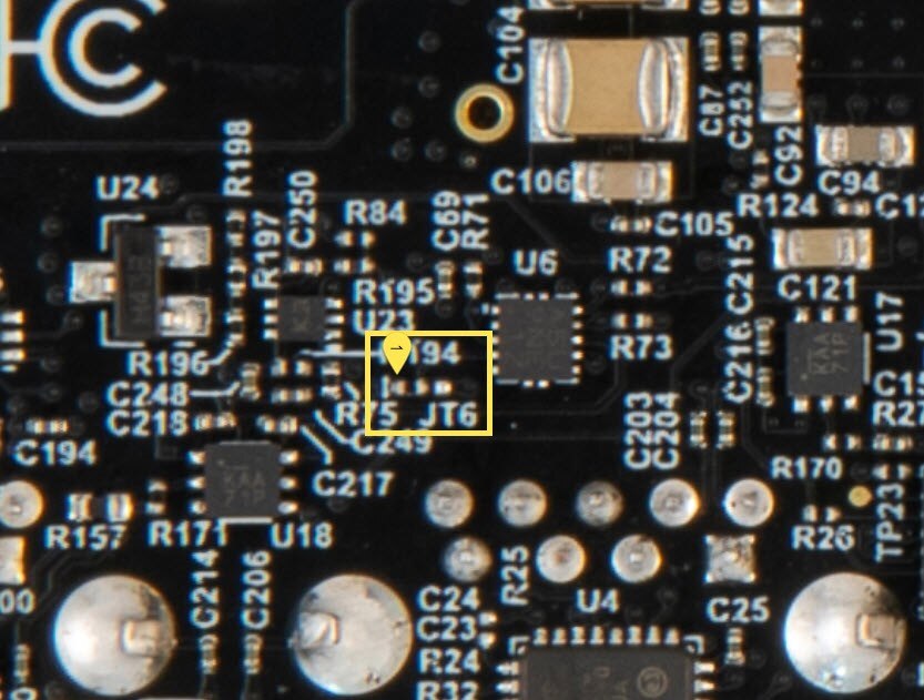
For those that want to modify the power-up initialization from push-button control to power-up with power connected, you will need to move a single resistor on the Ultra96-V2. This is the 3-pad, 10-Kohm resistor JT6, which selects either pull-down (default, use Push Button) or pull-up (power up with power). To implement the Power Up with Power Connected function, move the JT6 from position 1-2 to position 2-3. JT6 is located on the backside of the Ultra96-V2, so you will first need to remove the heatsink. JT6 is then located in the upper right of the southwest quadrant, near U6 as highlighted in the photo below.
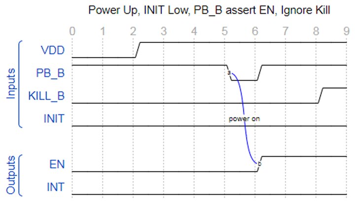
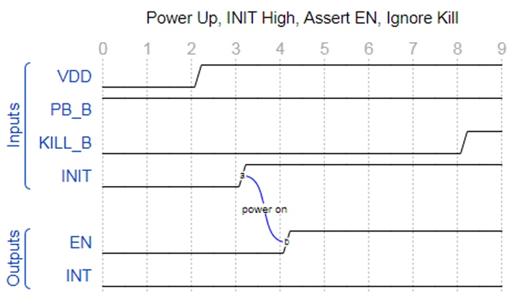
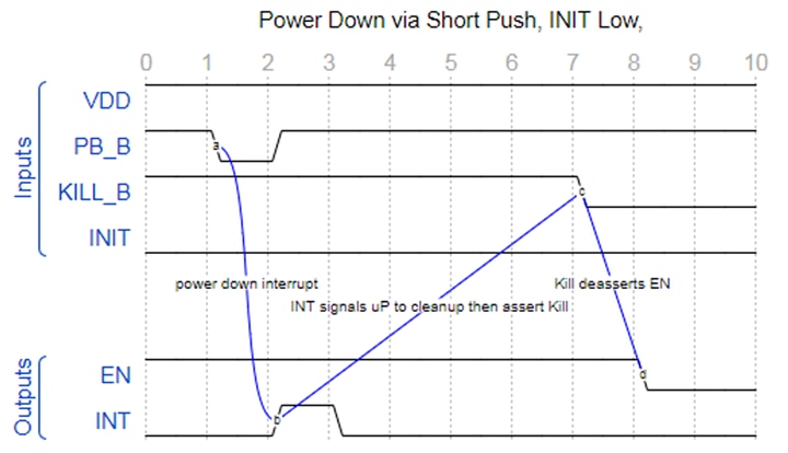
To help explain the functionality of this device, a datasheet is available at Dialog SLG4G42480 On-Off Controller Datasheet . Also, here are several functional diagrams showing the logic within this device.
In summary, the Xilinx Zynq UltraScale+ MPSoC's PMU offers many great system advantages. Having an inexpensive, small, customized On/Off Controller on the Ultra96-V2 is a great way to take advantage of some of these features.
Top Comments
-

jrhtech
-
Cancel
-
Vote Up
0
Vote Down
-
-
Sign in to reply
-
More
-
Cancel
Comment-

jrhtech
-
Cancel
-
Vote Up
0
Vote Down
-
-
Sign in to reply
-
More
-
Cancel
Children