element14 Community
element14 Community
    Register Log In
  • Site
  • Search
  • Log In Register
  • About Us
  • Community Hub
    Community Hub
    • What's New on element14
    • Feedback and Support
    • Benefits of Membership
    • Personal Blogs
    • Members Area
    • Achievement Levels
  • Learn
    Learn
    • Ask an Expert
    • eBooks
    • element14 presents
    • Learning Center
    • Tech Spotlight
    • STEM Academy
    • Webinars, Training and Events
    • Learning Groups
  • Technologies
    Technologies
    • 3D Printing
    • FPGA
    • Industrial Automation
    • Internet of Things
    • Power & Energy
    • Sensors
    • Technology Groups
  • Challenges & Projects
    Challenges & Projects
    • Design Challenges
    • element14 presents Projects
    • Project14
    • Arduino Projects
    • Raspberry Pi Projects
    • Project Groups
  • Products
    Products
    • Arduino
    • Avnet Boards Community
    • Dev Tools
    • Manufacturers
    • Multicomp Pro
    • Product Groups
    • Raspberry Pi
    • RoadTests & Reviews
  • Store
    Store
    • Visit Your Store
    • Choose another store...
      • Europe
      •  Austria (German)
      •  Belgium (Dutch, French)
      •  Bulgaria (Bulgarian)
      •  Czech Republic (Czech)
      •  Denmark (Danish)
      •  Estonia (Estonian)
      •  Finland (Finnish)
      •  France (French)
      •  Germany (German)
      •  Hungary (Hungarian)
      •  Ireland
      •  Israel
      •  Italy (Italian)
      •  Latvia (Latvian)
      •  
      •  Lithuania (Lithuanian)
      •  Netherlands (Dutch)
      •  Norway (Norwegian)
      •  Poland (Polish)
      •  Portugal (Portuguese)
      •  Romania (Romanian)
      •  Russia (Russian)
      •  Slovakia (Slovak)
      •  Slovenia (Slovenian)
      •  Spain (Spanish)
      •  Sweden (Swedish)
      •  Switzerland(German, French)
      •  Turkey (Turkish)
      •  United Kingdom
      • Asia Pacific
      •  Australia
      •  China
      •  Hong Kong
      •  India
      •  Korea (Korean)
      •  Malaysia
      •  New Zealand
      •  Philippines
      •  Singapore
      •  Taiwan
      •  Thailand (Thai)
      • Americas
      •  Brazil (Portuguese)
      •  Canada
      •  Mexico (Spanish)
      •  United States
      Can't find the country/region you're looking for? Visit our export site or find a local distributor.
  • Translate
  • Profile
  • Settings
FPGA
  • Technologies
  • More
FPGA
Forum Vivado and Zynq: TRI-STATE help
  • Blog
  • Forum
  • Documents
  • Quiz
  • Events
  • Polls
  • Files
  • Members
  • Mentions
  • Sub-Groups
  • Tags
  • More
  • Cancel
  • New
Join FPGA to participate - click to join for free!
Actions
  • Share
  • More
  • Cancel
Forum Thread Details
  • State Not Answered
  • +1 person also asked this people also asked this
  • Replies 31 replies
  • Subscribers 545 subscribers
  • Views 14432 views
  • Users 0 members are here
  • zynq
  • vivado
Related

Vivado and Zynq: TRI-STATE help

Jan Cumps
Jan Cumps over 3 years ago

I'm trying to write i2c code for Zynq, in VHDL.
I have difficulties creating a TRI-STATE pin.

The output logic should be: the pin is either pulled down to 0, or open-collector.
I have a pull-up resistor between that pin and VCC (3.3 V).
I'm expecting that if I write '0', it is low. When I write 'Z', it's open collector and pulled high by my pullup.
But in my design, the pin stays low. 0.62 V.

I thought, from reading up, that I should be done by:

  • defining the pin as INOUT
  • when you want to drive it low, assign '0'.
  • when you want to drive it open collector, assign 'Z'.
  • put an external pullup between pin and VCC

I created a testbed that puts the pin in "Z' mode, except when reset is asserted (via an external button).
In my testbed I also added a test pin, that I attach to an LED, that is high when the reset is asserted.
I connected a multimeter to the output.

The LED behaves as expected. It lights up when I assert the reset.
But the tri-state pin stays low, whether I write '0' or 'Z' to it. 

entity tristate_test is
    Port ( 
    reset_n: in std_logic;
    reset_out: out std_logic;
    tristate_pin : inout std_logic);
end tristate_test;

architecture Behavioral of tristate_test is

begin

reset_active: process (reset_n) is

begin
  if (reset_n = '0') then
    tristate_pin <= '0';
    reset_out <= '1';
  else
    tristate_pin <= 'Z';
    reset_out <= '0';
  end if;
end process reset_active;

end Behavioral;

Here is how I set the constraint:

image

set_property PACKAGE_PIN Y18 [get_ports tristate_pin_0]
set_property IOSTANDARD LVCMOS33 [get_ports tristate_pin_0]
set_property DRIVE 12 [get_ports tristate_pin_0]

Schema:

image

PMOD A pin 1 is PACKAGE_PIN Y18

What am I doing wrong?

  • Sign in to reply
  • Cancel

Top Replies

  • jc2048
    jc2048 over 3 years ago +4
    It might be a problem with hierarchy with the drag-and-drop stuff. An answer to this support question suggests that you need to set the synthesis to flatten the hierachy so that the tristate-ness can propagate…
  • jc2048
    jc2048 over 3 years ago in reply to bhfletcher +4
    Once you understand that the block-based design is an entity that could be used as part of a larger, more traditional design, the issue with the top-level wrapper becomes clearer. If the user is just using…
  • rachaelp
    rachaelp over 3 years ago +3
    Hi Jan, Just create the tristate in an assignment and not in a process. Not sure why what you have isn't working, have you looked at the schematic for what it's creating in Vivado? I guess maybe it's…
Parents
  • rachaelp
    0 rachaelp over 3 years ago

    Hi Jan,

    Just create the tristate in an assignment and not in a process. Not sure why what you have isn't working, have you looked at the schematic for what it's creating in Vivado? I guess maybe it's inferred a latch you aren't expecting maybe?

    tristate_pin <= '0' when reset_n = '0' else 'Z';
    reset_out <= '1' when reset_n = '0' else '0';

    Best Regards,

    Rachael

    • Cancel
    • Vote Up +3 Vote Down
    • Sign in to reply
    • Verify Answer
    • Cancel
  • Jan Cumps
    0 Jan Cumps over 3 years ago in reply to rachaelp

    I tried it outside of a process too. Just assigned a fixed value 'Z' in the architecture. The effect was the same.

    • Cancel
    • Vote Up 0 Vote Down
    • Sign in to reply
    • Verify Answer
    • Cancel
  • Jan Cumps
    0 Jan Cumps over 3 years ago in reply to jc2048

    I'm reading up. There's no IOBUF block that I can add on the block design - been searching for that.

    Keep in mind I have absolutely no experience of Vivado, nor the block designer tool,

    I have experience with the things that work. Once I get into trouble, I'm not familiar enough yet to self-solve.
    Previous mishaps I could fix with a mix of documentation and Google. For this one that path wasn't successful. That's when I branched off into this forum question.

    I'll get back when I have the outcome of the experiments above ...

    • Cancel
    • Vote Up 0 Vote Down
    • Sign in to reply
    • Verify Answer
    • Cancel
  • Jan Cumps
    0 Jan Cumps over 3 years ago in reply to Jan Cumps

    Currently at Tristate Description Using Combinatorial Process Implemented with OBUFT Coding Example (VHDL) 

    Page 81

    ...

    --
     port(
     T : in std_logic;
     I : in std_logic;
     O : out std_logic
     );
    --
     process(I, T)
     begin
       if (T = '0') then
         O <= I;
       else
         O <= 'Z';
       end if;
     end process;
    --

    • Cancel
    • Vote Up 0 Vote Down
    • Sign in to reply
    • Verify Answer
    • Cancel
  • Jan Cumps
    0 Jan Cumps over 3 years ago in reply to Jan Cumps

    This hasn't brought me farther.... I tried pins with name_T, name_I, name_O and couldn't get the wrapper to auto_generate a buffer.
    Read some more, tried to instantiate a Utility Buffer myself. But I could not turn it into a working design. 

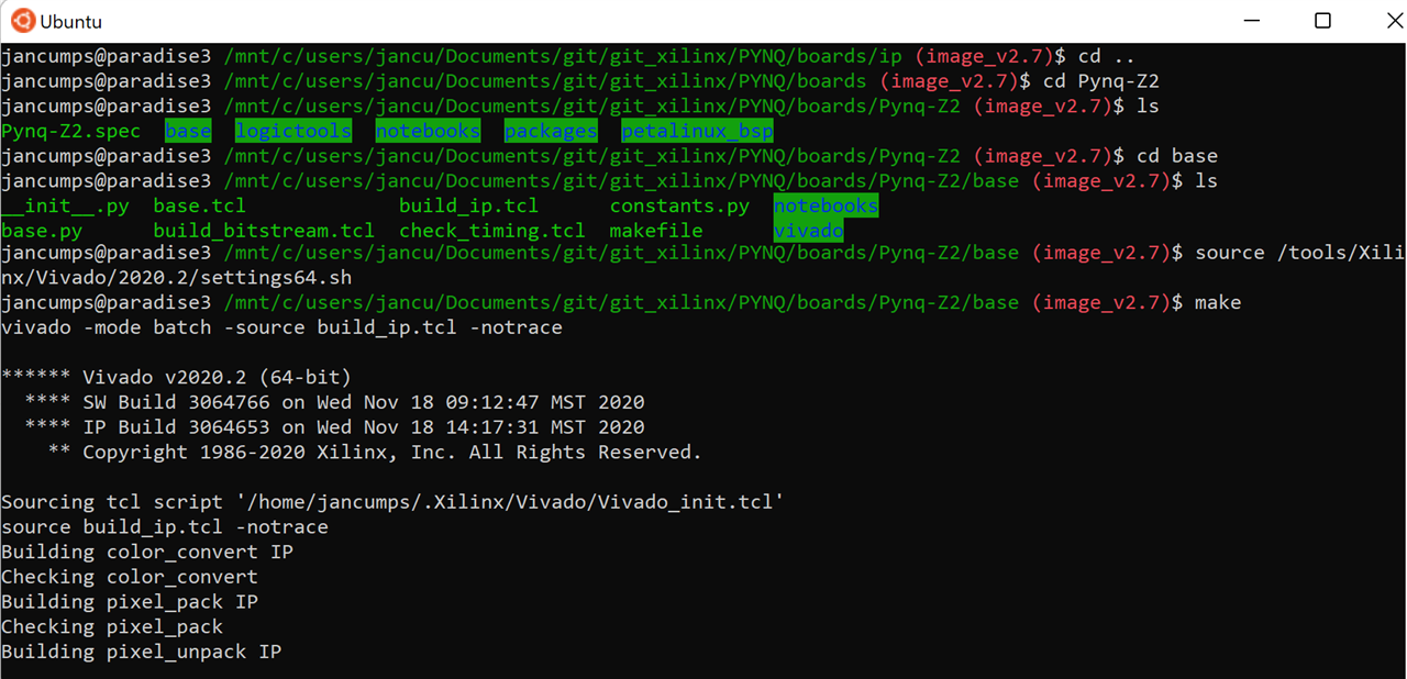
    Current approach: I cloned Xilinx' PYNQ repository, and I'm regenerating the BASE overlay project.
    It implements an I2C on the Arduino header - hoping that I can learn from that.
    Not sure though - I thought by reviewing this the last time, that they use a bespoke Xilinx I2C IP...

    image

    image: regenerate the PYNQ base overlay project from source, in Windows Sublayer for Linux.

    • Cancel
    • Vote Up +1 Vote Down
    • Sign in to reply
    • Verify Answer
    • Cancel
  • jc2048
    0 jc2048 over 3 years ago in reply to Jan Cumps

    "I tried pins with name_T, name_I, name_O"

    What did the schematic view show when you did that? Was there still just an OBUF attached to name_O? Did it do anything with the other two?

    • Cancel
    • Vote Up 0 Vote Down
    • Sign in to reply
    • Verify Answer
    • Cancel
  • Jan Cumps
    0 Jan Cumps over 3 years ago in reply to jc2048

    When I generated the wrapper - the moment where I was expecting magic to happen -I get errors for unconnected pins.

    • Cancel
    • Vote Up 0 Vote Down
    • Sign in to reply
    • Verify Answer
    • Cancel
  • jc2048
    0 jc2048 over 3 years ago in reply to Jan Cumps

    What does your tristate_test code in the block look like now? Can you show it to us?

    • Cancel
    • Vote Up 0 Vote Down
    • Sign in to reply
    • Verify Answer
    • Cancel
  • Jan Cumps
    0 Jan Cumps over 3 years ago in reply to jc2048

    The IP code  - one of the many incarnations. I tried different combinations, directions, with and without process:

    library IEEE;
    use IEEE.STD_LOGIC_1164.ALL;
    
    entity tristate_test is
        Port ( 
        reset_n: in std_logic;
        reset_out: out std_logic;
        tri_T : out std_logic;
        tri_I : in std_logic;    
        tri_O : out std_logic);
    end tristate_test;
    
    architecture Behavioral of tristate_test is
    
    begin
    
    reset_active: process (reset_n) is
    
    begin
    null;
    end process reset_active;
    
     
    reset_out <= '1' when reset_n = '0' else '0';
    tri_O <= 'Z' when reset_n = '0' else '0';
    tri_T <= '1' when reset_n = '0' else '0';
    
    end Behavioral;

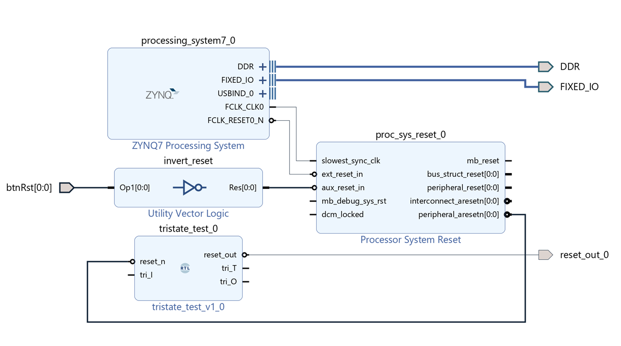
    The block design - I deliberately do not make ports external or assign a pin to them, because the manual says they need to be unconnected and not external

    image

    The wrapper code and the error message generated while wrapping:

    image

    --Copyright 1986-2020 Xilinx, Inc. All Rights Reserved.
    ----------------------------------------------------------------------------------
    --Tool Version: Vivado v.2020.2 (win64) Build 3064766 Wed Nov 18 09:12:45 MST 2020
    --Date        : Wed Feb  9 11:15:06 2022
    --Host        : paradise3 running 64-bit major release  (build 9200)
    --Command     : generate_target design_1_wrapper.bd
    --Design      : design_1_wrapper
    --Purpose     : IP block netlist
    ----------------------------------------------------------------------------------
    library IEEE;
    use IEEE.STD_LOGIC_1164.ALL;
    library UNISIM;
    use UNISIM.VCOMPONENTS.ALL;
    entity design_1_wrapper is
      port (
        DDR_addr : inout STD_LOGIC_VECTOR ( 14 downto 0 );
        DDR_ba : inout STD_LOGIC_VECTOR ( 2 downto 0 );
        DDR_cas_n : inout STD_LOGIC;
        DDR_ck_n : inout STD_LOGIC;
        DDR_ck_p : inout STD_LOGIC;
        DDR_cke : inout STD_LOGIC;
        DDR_cs_n : inout STD_LOGIC;
        DDR_dm : inout STD_LOGIC_VECTOR ( 3 downto 0 );
        DDR_dq : inout STD_LOGIC_VECTOR ( 31 downto 0 );
        DDR_dqs_n : inout STD_LOGIC_VECTOR ( 3 downto 0 );
        DDR_dqs_p : inout STD_LOGIC_VECTOR ( 3 downto 0 );
        DDR_odt : inout STD_LOGIC;
        DDR_ras_n : inout STD_LOGIC;
        DDR_reset_n : inout STD_LOGIC;
        DDR_we_n : inout STD_LOGIC;
        FIXED_IO_ddr_vrn : inout STD_LOGIC;
        FIXED_IO_ddr_vrp : inout STD_LOGIC;
        FIXED_IO_mio : inout STD_LOGIC_VECTOR ( 53 downto 0 );
        FIXED_IO_ps_clk : inout STD_LOGIC;
        FIXED_IO_ps_porb : inout STD_LOGIC;
        FIXED_IO_ps_srstb : inout STD_LOGIC;
        btnRst : in STD_LOGIC_VECTOR ( 0 to 0 );
        reset_out_0 : out STD_LOGIC
      );
    end design_1_wrapper;
    
    architecture STRUCTURE of design_1_wrapper is
      component design_1 is
      port (
        btnRst : in STD_LOGIC_VECTOR ( 0 to 0 );
        DDR_cas_n : inout STD_LOGIC;
        DDR_cke : inout STD_LOGIC;
        DDR_ck_n : inout STD_LOGIC;
        DDR_ck_p : inout STD_LOGIC;
        DDR_cs_n : inout STD_LOGIC;
        DDR_reset_n : inout STD_LOGIC;
        DDR_odt : inout STD_LOGIC;
        DDR_ras_n : inout STD_LOGIC;
        DDR_we_n : inout STD_LOGIC;
        DDR_ba : inout STD_LOGIC_VECTOR ( 2 downto 0 );
        DDR_addr : inout STD_LOGIC_VECTOR ( 14 downto 0 );
        DDR_dm : inout STD_LOGIC_VECTOR ( 3 downto 0 );
        DDR_dq : inout STD_LOGIC_VECTOR ( 31 downto 0 );
        DDR_dqs_n : inout STD_LOGIC_VECTOR ( 3 downto 0 );
        DDR_dqs_p : inout STD_LOGIC_VECTOR ( 3 downto 0 );
        FIXED_IO_mio : inout STD_LOGIC_VECTOR ( 53 downto 0 );
        FIXED_IO_ddr_vrn : inout STD_LOGIC;
        FIXED_IO_ddr_vrp : inout STD_LOGIC;
        FIXED_IO_ps_srstb : inout STD_LOGIC;
        FIXED_IO_ps_clk : inout STD_LOGIC;
        FIXED_IO_ps_porb : inout STD_LOGIC;
        reset_out_0 : out STD_LOGIC
      );
      end component design_1;
    begin
    design_1_i: component design_1
         port map (
          DDR_addr(14 downto 0) => DDR_addr(14 downto 0),
          DDR_ba(2 downto 0) => DDR_ba(2 downto 0),
          DDR_cas_n => DDR_cas_n,
          DDR_ck_n => DDR_ck_n,
          DDR_ck_p => DDR_ck_p,
          DDR_cke => DDR_cke,
          DDR_cs_n => DDR_cs_n,
          DDR_dm(3 downto 0) => DDR_dm(3 downto 0),
          DDR_dq(31 downto 0) => DDR_dq(31 downto 0),
          DDR_dqs_n(3 downto 0) => DDR_dqs_n(3 downto 0),
          DDR_dqs_p(3 downto 0) => DDR_dqs_p(3 downto 0),
          DDR_odt => DDR_odt,
          DDR_ras_n => DDR_ras_n,
          DDR_reset_n => DDR_reset_n,
          DDR_we_n => DDR_we_n,
          FIXED_IO_ddr_vrn => FIXED_IO_ddr_vrn,
          FIXED_IO_ddr_vrp => FIXED_IO_ddr_vrp,
          FIXED_IO_mio(53 downto 0) => FIXED_IO_mio(53 downto 0),
          FIXED_IO_ps_clk => FIXED_IO_ps_clk,
          FIXED_IO_ps_porb => FIXED_IO_ps_porb,
          FIXED_IO_ps_srstb => FIXED_IO_ps_srstb,
          btnRst(0) => btnRst(0),
          reset_out_0 => reset_out_0
        );
    end STRUCTURE;
    

    The buffer wasn't instantiated. I was expecting that to happen because the pins _I, _O and _T are available

    Schematic after synthesis:

    image

    • Cancel
    • Vote Up 0 Vote Down
    • Sign in to reply
    • Verify Answer
    • Cancel
  • jc2048
    0 jc2048 over 3 years ago in reply to Jan Cumps

    Line 25. Just set tri_O to '0' (the level you want at the output of the IOBUF, when it's enabled, to give you your pretend open-drain output). The tristating is done by the external buffer, not at the block's port.

    It's possible you might need to do something with the tri_I. Perhaps just take the value that comes from it and then push it back out on another output like you've done with the reset_n. I'm saying that just in case it gets optimised away as not doing anything and then the rest gets upset because it isn't there any longer.

    • Cancel
    • Vote Up 0 Vote Down
    • Sign in to reply
    • Verify Answer
    • Cancel
  • Jan Cumps
    0 Jan Cumps over 3 years ago in reply to jc2048

    Yes, the traditional individual OBuffer / IBuffer depending on direction, if I manually made them external.
    Input grounded and buffer not connected to anything (nc) if I left them flapping in the breeze.

    • Cancel
    • Vote Up 0 Vote Down
    • Sign in to reply
    • Verify Answer
    • Cancel
  • Jan Cumps
    0 Jan Cumps over 3 years ago in reply to Jan Cumps

    This is how the PYNQ team does it. It's a snippet from the PMOD hierarchy of the BASE (proof of concept) overlay.

    image

    The output pin (pmoda_gpio) is Xilinx specific, a MASTER interface pin of Xilinx predefined type gpio_rtl. I know how to make that.
    The block on the left of that (io_switch_xxx) is a custom PYNQ IP. I believe that I'll be able to find the source code. Most likely Verilog - but I may be able to understand it ...

    • Cancel
    • Vote Up 0 Vote Down
    • Sign in to reply
    • Verify Answer
    • Cancel
Reply
  • Jan Cumps
    0 Jan Cumps over 3 years ago in reply to Jan Cumps

    This is how the PYNQ team does it. It's a snippet from the PMOD hierarchy of the BASE (proof of concept) overlay.

    image

    The output pin (pmoda_gpio) is Xilinx specific, a MASTER interface pin of Xilinx predefined type gpio_rtl. I know how to make that.
    The block on the left of that (io_switch_xxx) is a custom PYNQ IP. I believe that I'll be able to find the source code. Most likely Verilog - but I may be able to understand it ...

    • Cancel
    • Vote Up 0 Vote Down
    • Sign in to reply
    • Verify Answer
    • Cancel
Children
No Data
element14 Community

element14 is the first online community specifically for engineers. Connect with your peers and get expert answers to your questions.

  • Members
  • Learn
  • Technologies
  • Challenges & Projects
  • Products
  • Store
  • About Us
  • Feedback & Support
  • FAQs
  • Terms of Use
  • Privacy Policy
  • Legal and Copyright Notices
  • Sitemap
  • Cookies

An Avnet Company © 2025 Premier Farnell Limited. All Rights Reserved.

Premier Farnell Ltd, registered in England and Wales (no 00876412), registered office: Farnell House, Forge Lane, Leeds LS12 2NE.

ICP 备案号 10220084.

Follow element14

  • X
  • Facebook
  • linkedin
  • YouTube