element14 Community
element14 Community
    Register Log In
  • Site
  • Search
  • Log In Register
  • About Us
  • Community Hub
    Community Hub
    • What's New on element14
    • Feedback and Support
    • Benefits of Membership
    • Personal Blogs
    • Members Area
    • Achievement Levels
  • Learn
    Learn
    • Ask an Expert
    • eBooks
    • element14 presents
    • Learning Center
    • Tech Spotlight
    • STEM Academy
    • Webinars, Training and Events
    • Learning Groups
  • Technologies
    Technologies
    • 3D Printing
    • FPGA
    • Industrial Automation
    • Internet of Things
    • Power & Energy
    • Sensors
    • Technology Groups
  • Challenges & Projects
    Challenges & Projects
    • Design Challenges
    • element14 presents Projects
    • Project14
    • Arduino Projects
    • Raspberry Pi Projects
    • Project Groups
  • Products
    Products
    • Arduino
    • Avnet Boards Community
    • Dev Tools
    • Manufacturers
    • Multicomp Pro
    • Product Groups
    • Raspberry Pi
    • RoadTests & Reviews
  • Store
    Store
    • Visit Your Store
    • Choose another store...
      • Europe
      •  Austria (German)
      •  Belgium (Dutch, French)
      •  Bulgaria (Bulgarian)
      •  Czech Republic (Czech)
      •  Denmark (Danish)
      •  Estonia (Estonian)
      •  Finland (Finnish)
      •  France (French)
      •  Germany (German)
      •  Hungary (Hungarian)
      •  Ireland
      •  Israel
      •  Italy (Italian)
      •  Latvia (Latvian)
      •  
      •  Lithuania (Lithuanian)
      •  Netherlands (Dutch)
      •  Norway (Norwegian)
      •  Poland (Polish)
      •  Portugal (Portuguese)
      •  Romania (Romanian)
      •  Russia (Russian)
      •  Slovakia (Slovak)
      •  Slovenia (Slovenian)
      •  Spain (Spanish)
      •  Sweden (Swedish)
      •  Switzerland(German, French)
      •  Turkey (Turkish)
      •  United Kingdom
      • Asia Pacific
      •  Australia
      •  China
      •  Hong Kong
      •  India
      •  Korea (Korean)
      •  Malaysia
      •  New Zealand
      •  Philippines
      •  Singapore
      •  Taiwan
      •  Thailand (Thai)
      • Americas
      •  Brazil (Portuguese)
      •  Canada
      •  Mexico (Spanish)
      •  United States
      Can't find the country/region you're looking for? Visit our export site or find a local distributor.
  • Translate
  • Profile
  • Settings
FPGA
  • Technologies
  • More
FPGA
Forum Arty S7 rev B vs Arty S7 rev E? Somewhat confused.
  • Blog
  • Forum
  • Documents
  • Quiz
  • Events
  • Polls
  • Files
  • Members
  • Mentions
  • Sub-Groups
  • Tags
  • More
  • Cancel
  • New
Join FPGA to participate - click to join for free!
Actions
  • Share
  • More
  • Cancel
Forum Thread Details
  • Replies 16 replies
  • Subscribers 551 subscribers
  • Views 5133 views
  • Users 0 members are here
  • spartan 7
  • 7_ways_to_leave_your_spartan-6
  • 7 Ways to Leave Your Spartan-6
  • fpga
  • arty s7
  • Spartan_Migration
Related

Arty S7 rev B vs Arty S7 rev E? Somewhat confused.

javagoza
javagoza over 3 years ago

I received the Digilent Arty S7 50 rev B Board for the  7 Ways to Leave Your Spartan-6 FPGA program. See intro blog: Arty S7 50 First Power Up and Hardware-Only Blinky

According to this Digilent forum post the rev B should be released sometime in 2017 

https://forum.digilent.com/topic/22950-about-arty-s7-50-board/?do=findComment&comment=67181

Looking for the Master XDC Xilinx Synopsys Design Constraint (SDC) I've found two versions under two different Digilent repositories. The xdc for revision E is under the Master XDC files for Digilent FPGA and Zynq boards repository, while the version for rev B is under its own repository

## This file is a general .xdc for the ARTY Rev. B

https://github.com/Digilent/Arty-S7-50-base-uc/blob/master/src/constraints/Arty-S7-50-Master.xdc

## This file is a general .xdc for the Arty S7-50 Rev. E

https://github.com/Digilent/digilent-xdc/blob/master/Arty-S7-50-Master.xdc

There are differences between the two constraints files but I am not able to identify if they are just changes in the names of some ports and comments or if they are more important.

But I refer them in case someone runs into trouble using the newer file's constraints and wants to make sure it's not an old constraint he has to use.

On the reference documentation page there are links to three versions of the Arty S7 board schematics

  • Arty S7 Revision E.2 Schematic
  • Arty S7 Revision E.1 Schematic
  • Arty S7 Revision B.0 Schematic

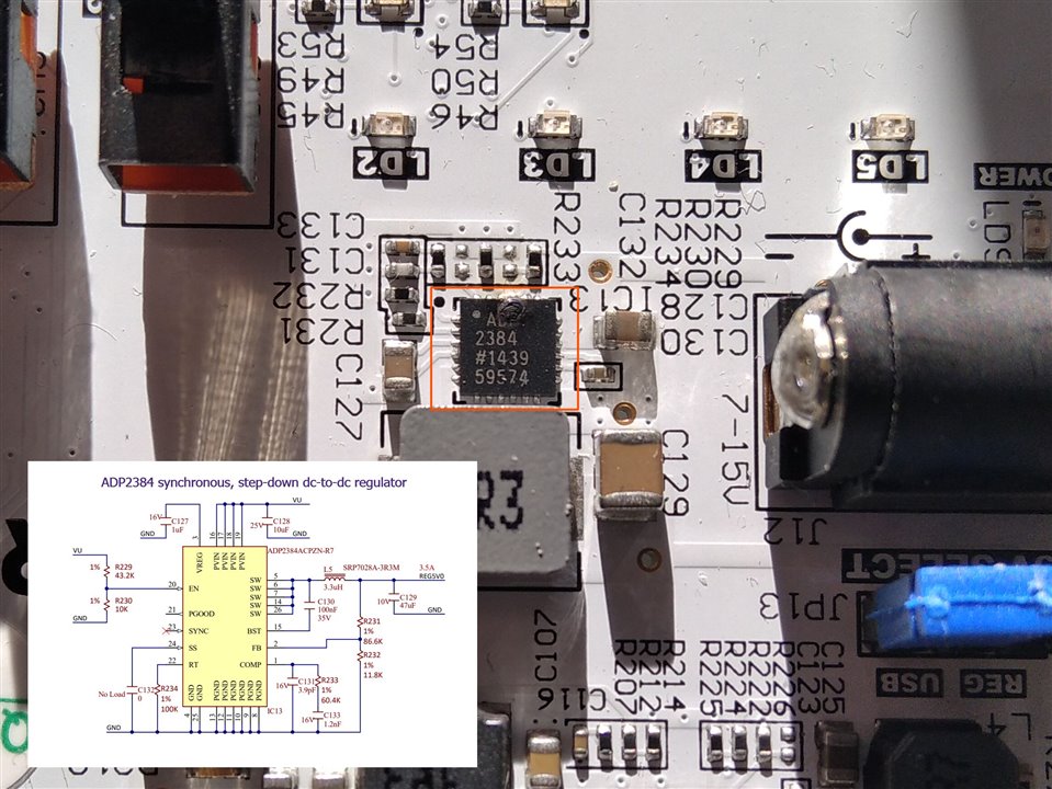
The main changes between version B and version E seem to be the voltage regulation circuit and the DDR3 memory circuit.

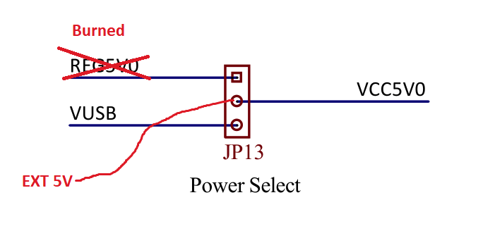
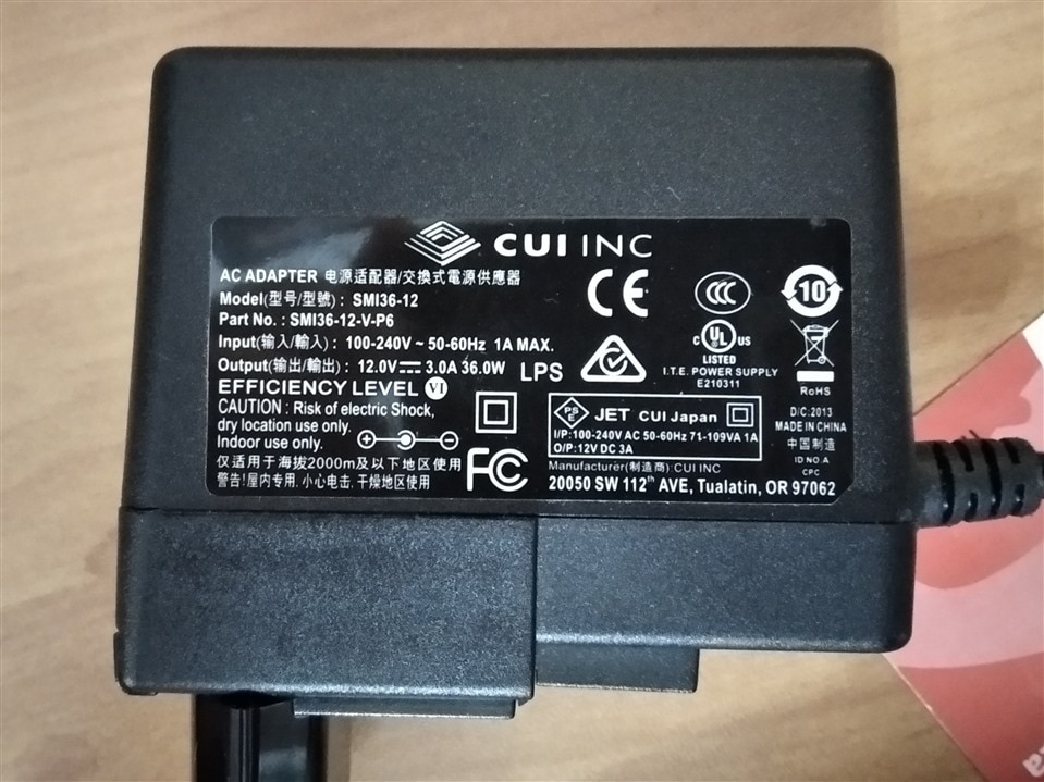
I am having trouble powering the board from a battery or from a power supply. The board turns on but then it starts to smell like a burnt circuit as if there is a short circuit somewhere.

Has anyone tried to power the board from any 7V-15V external power source?

  • Sign in to reply
  • Cancel

Top Replies

  • misaz
    misaz over 3 years ago +3
    I also received Rev B (my silkscreen is quite bad here, it looks like rev rectangle, but I think it is letter B). Serial number starts with 21, so I gues board was manufactured in 2021. According to Reference…
  • misaz
    misaz over 3 years ago in reply to javagoza +3
    What voltage did you provided to the regulator and where did you connected it? Regulator itself is quite flexible allowing voltage as high as 20V. Did not you swap polarity? It is still interesting…
  • ralphjy
    ralphjy over 3 years ago in reply to javagoza +3
    Glad to hear that your board is still working. At least you have the option of using an external 5V power supply if you need more current. Not sure I have a suitable DC adapter with a 2.5/2.1mm plug, so…
Parents
  • misaz
    misaz over 3 years ago

    I also received Rev B (my silkscreen is quite bad here, it looks like rev rectangle, but I think it is letter B). Serial number starts with 21, so I gues board was manufactured in 2021. According to Reference Manual power circuit was changed between revisions C and E. Use this documentation: https://digilent.com/reference/programmable-logic/arty-s7/reference-manual/power_supplies_rev_c. I checked it and my board is older design with AD2384 regulator.   https://www.analog.com/en/products/adp2384.html

    Have you switched jumper J13 before connecting power supply? Can you identify burned chip (= chip which smell the most)? Do you see any black or brown burned wire at top or bottom of board? Maybe you burned only some power regulator and FPGA remained safe. Theoreticaly all regulaters could be baypassed somehow. 5V you can provide manualy using JP13. If you burned ADP5052 which is used for converting 5V to 3 other lower voltages, then you will need to manualy provided 1V, 3.3V and 1.35V. 1V and 3.3V are avalaible at jumpers JP3 and JP4 (they are marked as no load in schematics, but my board contains pinheads soldered). 1.35V is most complicated. It is avalaible for example at SW3 (really, while it is mainly used for DDR memory, it is also avalaible on mechanical switch, most probably because switch is connected to the pin of bank powered by 1.35V).

    I recommend be extremely careful in this situation and before applying any power check all things at least 5 times. I remember from universite that many Digilent ZYBO boards also smelt burned but in fact everything worked well and I did not find any malfunction anytime. Maybe this is some design caveat and maybe your board will work fine even it smell.

    I also recommend testing short circuits (by digital multimeter for example) on all power domains (5V, 3.3V, 1.35V and 1V). Similarly all pins of JP13 should not be shorted with ground.

    When you switch back to USB supply, do your board work (remember set JP13 correctly first)?

    • Cancel
    • Vote Up +3 Vote Down
    • Sign in to reply
    • Cancel
  • javagoza
    javagoza over 3 years ago in reply to misaz

    Thanks misaz, I found the burned part the AD2384 regulator. 

    image

    I am working fine powering the board by USB. So for now I will not try to power it through the other port again.

    • Cancel
    • Vote Up +1 Vote Down
    • Sign in to reply
    • Cancel
  • misaz
    misaz over 3 years ago in reply to javagoza

    This is sad Disappointed . This regulator is used for converting VIN in range 6 - 20V to 5V and second independent option is using USB cable. If you want to use battery, then you will need to use external converter and provide 5V (check voltage before connecting) to JP13 pinhead used for selecting 5V source:

    image

    • Cancel
    • Vote Up +2 Vote Down
    • Sign in to reply
    • Cancel
  • misaz
    misaz over 3 years ago in reply to javagoza

    What voltage did you provided to the regulator and where did you connected it? Regulator itself is quite flexible allowing voltage as high as 20V. Did not you swap polarity?

    It is still interesting. You chip burned near EN, PGOOD and RT (frequency setting) pins which are as part of digital logic. It would be very interesting that digital logic caused this kind of burnout.

    If you are skilled in soldering TQFN parts, you can request free samples of ADP2384, solder new unit and try again.

    • Cancel
    • Vote Up +3 Vote Down
    • Sign in to reply
    • Cancel
  • javagoza
    javagoza over 3 years ago in reply to misaz

    Thanks again for your interest.

    I was using this AC Adapter, SMI36-12-V-P6 and running the preinstalled bitstream.

    CUI SMI36-12-V-P6

    https://uk.farnell.com/cui/smi36-12-v-p6/adapter-ac-dc-12v-3a/dp/3594793

    image

    • Cancel
    • Vote Up +2 Vote Down
    • Sign in to reply
    • Cancel
  • misaz
    misaz over 3 years ago in reply to javagoza

    wow, this is interesting. Polarity is correct and voltage is in limit with high tolerance. It looks that nobody know what happended inside ADP2384 exactly.

    • Cancel
    • Vote Up +1 Vote Down
    • Sign in to reply
    • Cancel
  • ralphjy
    ralphjy over 3 years ago in reply to javagoza

    Glad to hear that your board is still working.  At least you have the option of using an external 5V power supply if you need more current.  Not sure I have a suitable DC adapter with a 2.5/2.1mm plug, so I'll probably do that if necessary.  If I do find an adapter, I'll make sure there is 5V at the output of the regulator before I connect it.  

    That part looks extremely difficult to try to replace...

    Wonder why we got such old stock.  The date code on my board is 1728.

    • Cancel
    • Vote Up +3 Vote Down
    • Sign in to reply
    • Cancel
Reply
  • ralphjy
    ralphjy over 3 years ago in reply to javagoza

    Glad to hear that your board is still working.  At least you have the option of using an external 5V power supply if you need more current.  Not sure I have a suitable DC adapter with a 2.5/2.1mm plug, so I'll probably do that if necessary.  If I do find an adapter, I'll make sure there is 5V at the output of the regulator before I connect it.  

    That part looks extremely difficult to try to replace...

    Wonder why we got such old stock.  The date code on my board is 1728.

    • Cancel
    • Vote Up +3 Vote Down
    • Sign in to reply
    • Cancel
Children
  • javagoza
    javagoza over 3 years ago in reply to ralphjy

    Thanks ralphjy. Same mark on my board 1728.

    • Cancel
    • Vote Up +1 Vote Down
    • Sign in to reply
    • Cancel
  • misaz
    misaz over 3 years ago in reply to javagoza

    I originaly thought that board was manufactured in 2021 because serial number start with 21, but my board is also marked with 1728. (not that I am not sure if this code means date code) FPGA is marked with date code 1721 and this realy is date code accoridng to documentation, so at least FPGA chip definitely comes from 2017. RAM has 1718 on it, but I cannot check that it is date code because documentation is unavalaible. FTDI chip has date code 1621, so it comes even from 2016 in my case. Analog divece regulators have 1707 and 1439 codes on it. So it looks, they come from 2014 and 2017, but that I did not find any documentatio nsaying that this is date code. On your phote I see that your burned chip has also marking 1439.

    So it realy looks that boards which we received are quite old. But I think it is not important. Even regulator from 2014 should not do this.

    • Cancel
    • Vote Up +1 Vote Down
    • Sign in to reply
    • Cancel
element14 Community

element14 is the first online community specifically for engineers. Connect with your peers and get expert answers to your questions.

  • Members
  • Learn
  • Technologies
  • Challenges & Projects
  • Products
  • Store
  • About Us
  • Feedback & Support
  • FAQs
  • Terms of Use
  • Privacy Policy
  • Legal and Copyright Notices
  • Sitemap
  • Cookies

An Avnet Company © 2025 Premier Farnell Limited. All Rights Reserved.

Premier Farnell Ltd, registered in England and Wales (no 00876412), registered office: Farnell House, Forge Lane, Leeds LS12 2NE.

ICP 备案号 10220084.

Follow element14

  • X
  • Facebook
  • linkedin
  • YouTube