


Table of Contents
Introduction
A fellow radio enthusiast was looking for an RF power splitter, and of course these things are not easy to obtain at short notice; often they need to be ordered from overseas (I’m not aware of a local source), and they cost a lot!
I decided to give it a shot, and it was a one-day project, involving a bit of reading up, winding coils, and sitting in front of the VNA!
This very short (well, it was when I started it! it kind of grew..) blog post documents what I did, in case anyone else wants to make one, or to see how a VNA can be useful.
The photo might look scary due to the amount of windings, but everything is easier in smaller pieces, and actually this project is 3-in-one, each of the three sub-systems serve a purpose and can be individually tested.
Even if you’re not interested in a power splitter, but are interested in a balun or impedance transformation or just using a Vector Network Analyzer (VNA) then there may be something of interest in this blog post.
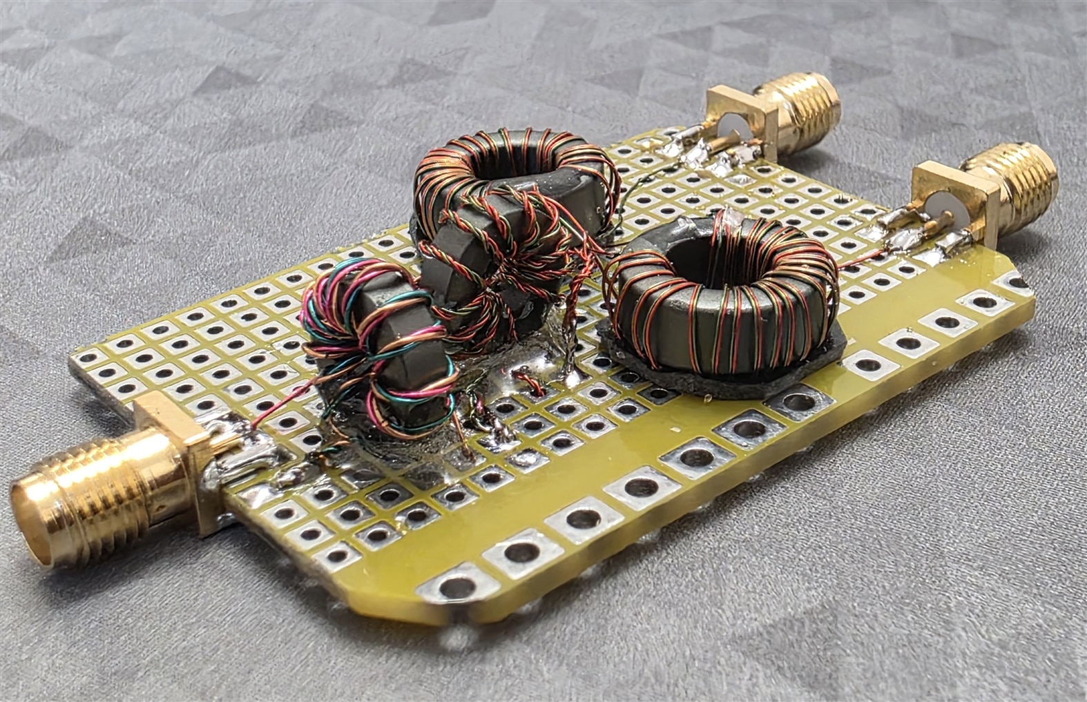
What Does the Splitter Do?
The power splitter has one input port, and two output ports (all SMA connectors in my case). Whatever RF arrives at the input, gets evenly split up across two ports, and it is a passive device, so half the power (-3dB) goes to each port in theory, but there will be some losses. The particular design I went with happens to do a 180 degree phase shift on one port compared to the other, which isn’t usually an issue (and is sometimes desired anyway).
RF power splitters can be broadband, meaning they operate at a range of frequencies. That’s the type I wanted to make, and it should cover 1-30 MHz range (known as High Frequency, or HF in the radio world).
The intended use-case for the splitter I made, was to feed radio signals, in radio receive mode, into two radio receivers simultaneously. This is a common problem where a user wishes to add software defined radio (SDR) reception in conjunction with whatever radio system they may already be using. There is other hardware which prevents the splitter being in the path during radio transmission, so there’s no possibility (hopefully!) for the splitter or the SDR receiver to see high power.
Designing and Testing
Very few tools were used – no LCR meter or oscilloscope or even spectrum analyzer or signal generator was needed. In fact, only a VNA was used, and it can be a very low-cost one such as NanoVNA, which is a surprisingly capable instrument.
If you're new to VNAs, what the VNA instrument does is generate a frequency sweep signal, and that travels out to the device-under-test. If that device has an impedance that matches 50 ohms, then no power will get reflected back, and the VNA looks out for the reflected power, and the phase shift, and uses that information to display (in various charts) the measurements across the frequency range of interest. It turns out that the measurements can be represented in different ways, for instance, as an impedance. Most VNAs will also be able to show what comes out of the other end of the device-under-test too, and that's useful to see how much loss occurred (again at different frequencies) for RF transiting through the device.
The basic procedure was to build things one subsystem at a time, and measure that subsystem in isolation, using the VNA. The steps are:
(1) Power up the VNA, and set it to the frequency range of interest (1-30 MHz in my case)
(2) Load your Calibration Kit details into it (if the VNA supports it). The photo here shows my cal kit; usually the bits and pieces can come with the NanoVNA (an extremely basic cal kit, but it will be fine for the frequencies of interest in this blog post), but for other VNAs, it is a separate purchase.
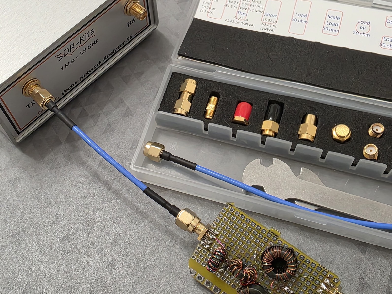
(3) Attach a short SMA cable (male-to-male SMA cable) to “Port 1” (VNAs usually have ports with specific numbers, and port 1 always provides the most frequently used capability called an S11 measurement.
(4) Make the VNA aware of the cable length (otherwise the measurements are meaningless) – this is usually done by performing a calibration (which involves applying the calibration kit pieces to the end of the SMA cable when requested.
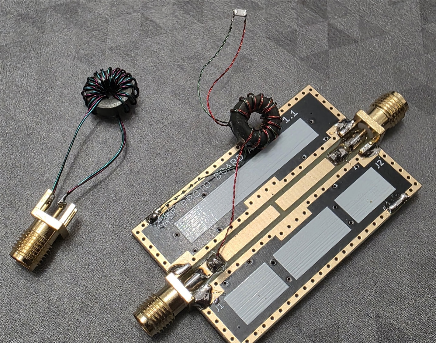
(5) Attach the wound component to the end of the SMA cable, and this is easiest if you have a female SMA connector that you can solder the component on to. The photo below shows a few methods that could be used. The leftmost example uses a bare connector, and the component happens to be wired for measuring inductance for common-mode signals. The rightmost example shows a reusable prototype test board. The thing being tested there is what percentage of power goes into the load at the other end (a resistor has been soldered there) and what percentage is reflected.
(6) Run a scan, and tell the VNA how you want the results displayed! Sometimes a Smith Chart is helpful, and other times you might want a normal x-y chart. The blog post shows both being used.
For designing with ferrite cores, I find the free Coil64 software to be extremely helpful, but there's no substitute for the VNA, because ferrite behavior is complicated (at least to me) and the VNA will allow you to make tweaks in near-real-time and see the effects even if something subtle was missed or misunderstood in the theory.
It helps to keep a small stock of ferrite cores, and any enamelled copper wire you can salvage perhaps. There is a large range of ferrite types and sizes, but in practise, it is still worthwhile just having a small set to play with. Ferrite type 43 is extremely popular for operation into VHF frequencies, and type 77 (which I used for this project) might be used in applications up to 50 MHz. Consider ferrite type 61 and 63 if you're interested in UHF. Some of the smaller ferrite cores only cost about $0.20 or $0.30 in quantities of 10 or 25, so a small set of cores doesn't have to be a large expense. For radio receiver type projects using ferrite cores from about 10 mm to 20 mm diameter, perhaps 0.2 mm and 0.3 mm enamelled copper wire is convenient.
Splitter Sub-System
The RF splitter needs a splitter sub-system : ) The literature out there includes a nice design by Ruthroff (in a paper titled “Some Broad-Band Transformers”, which uses a couple of ferrite cores and twisted wire.

Image Source: "Some Broad-Band Transformers", Ruthroff
These are often referred to as transmission-line transformers, or baluns, or “coil system” was one of the original terms but not used as much these days. Anyway, it turns out, that if you arrange two of these coil systems appropriately as shown in the diagram above, then splitting action will occur. There are a couple of issues however:
(1) You’ll notice that the input does not have a common connection to the outputs, i.e. there is no common ground, which could be problematic when attaching to typical radio equipment
(2) The input impedance is different to the output impedance; it is in fact half, and normally it is highly desirable to make all port impedances 50 ohm for interoperability with other equipment, with hopefully minimal power loss.
Those issues get solved in the next section of this blog, although it is the preceding section of the design (working backwards).
To construct the splitter sub-system, I built one of the coil systems, and then tested it with a vector network analyzer called VNWA (another option as mentioned earlier is NanoVNA; it would be very capable of these measurements too).
I was interested in two things;
(a) the common-mode impedance, which ought to be at least 500 ohm (i.e. ten times 50 ohms, although I prefer to aim for at least 20 times) at a bare minimum across the frequency range, and ideally higher, and
(b) the match to 50 ohm.
Both of these things were tested between 1 and 30 MHz.
This chart has markers at 1, 14 and 30 MHz. The red line here shows the common-mode impedance, and at 30 MHz, it is listed as 926 ohm, so I was happy with that. The blue line is above and below the horizon slightly, so there was resonance at some point (also can be seen from the red line going extremely high).
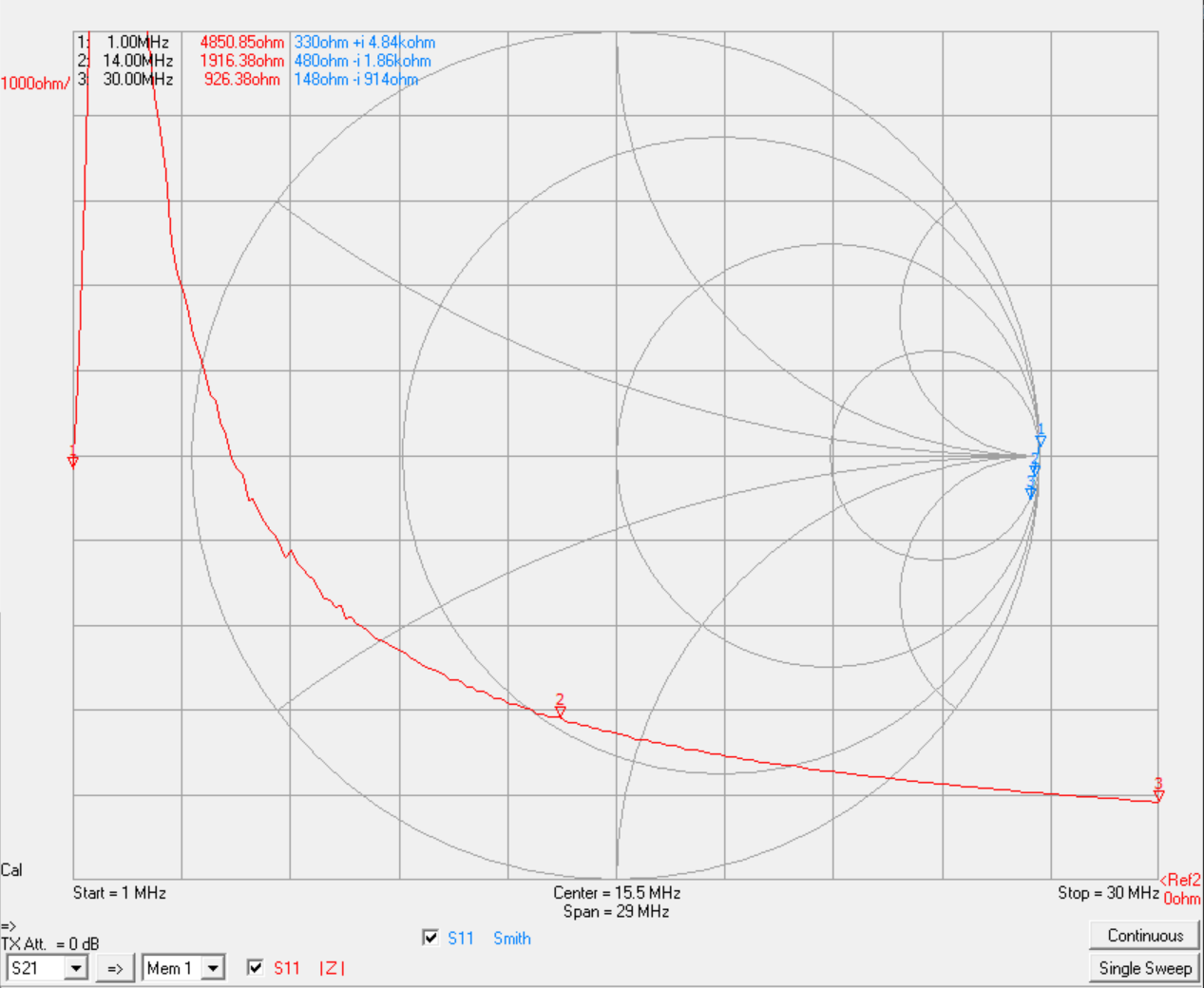
Here’s a chart showing the impedance when the other end of the windings are terminated with 50 ohms. As can be seen, the result is near-ideal, the plot is concentrated precisely at the 50 ohm center location in the Smith chart, across the entire frequency range.
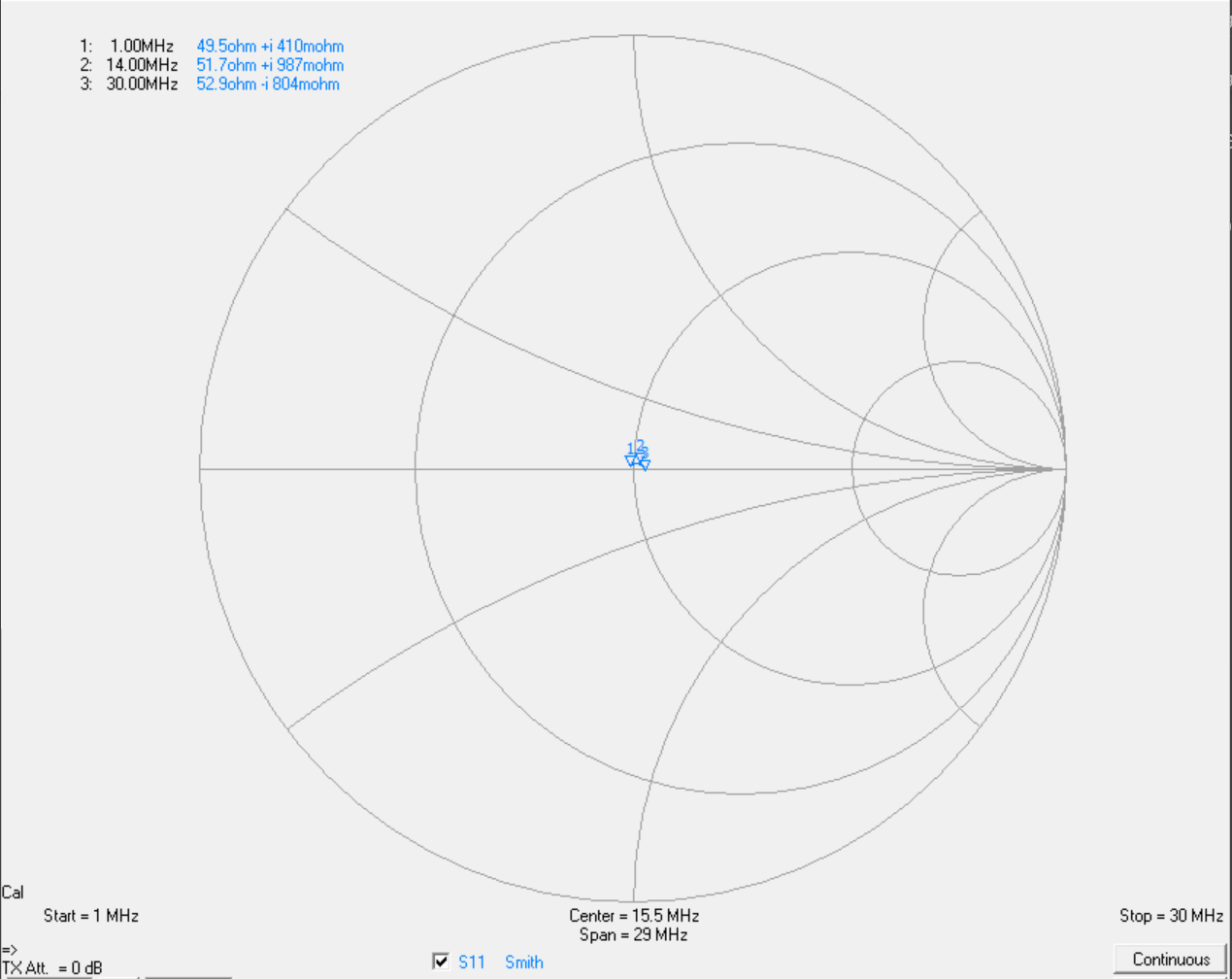
I repeated these measurements for a second coil system, so that I could be fairly sure both were reasonably matched. Then, I assembled the circuit, and put it to one side, since further tests for this would be best at the end.
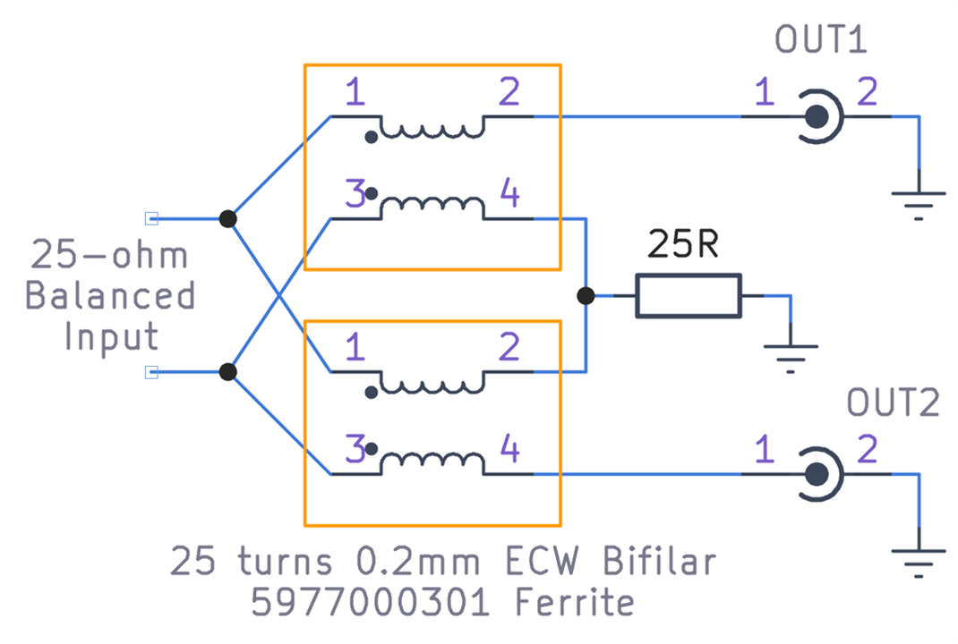
Note: In reality, I took two attempts; first I used a slightly smaller ferrite core, and couldn’t meet the rule to have at least 500 ohm for the common-mode impedance, so I then used a larger core and wound more turns. The diagram above shows the final ferrite core that was chosen. Also, it really helps if ready-made bifilar wire is used (i.e. wire that is already glued as a pair, so that it doesn’t need to be twisted. This sort of wire is hard to find however (I got some from ebay years ago) so the next-best option is to manually twist the wire, but try to do it near-identically for the two ferrites.
Balun Sub-System
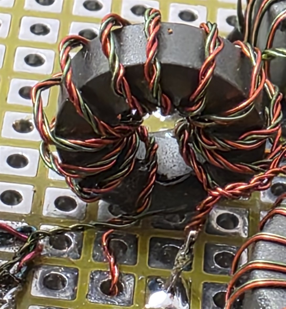
In order to get an unbalanced input (referred to ground), I prepended a balun to the section above. It’s normally fairly straightforward to construct this, you just need twisted wire wrapped around the ferrite enough times to build up a reasonable common-mode impedance. However, in this case, the balun was needed for 25 ohms, not 50 ohms, and that’s a little more tricky than usual, because that means the wire needs to be twisted a lot to bring the characteristic impedance of the transmission line down. My solution was to use four wires, not two, in the hope that the coupling would be physically closer. It did work, but I had two attempts, and picked the one with the best results, since I didn’t know precisely how much to twist (the answer was, the amount of twisting was extremely high, about one twist every two millimeters).
Just as with the previous section, I measured the common-mode impedance, and it was substantially greater than ten times 25 ohm:
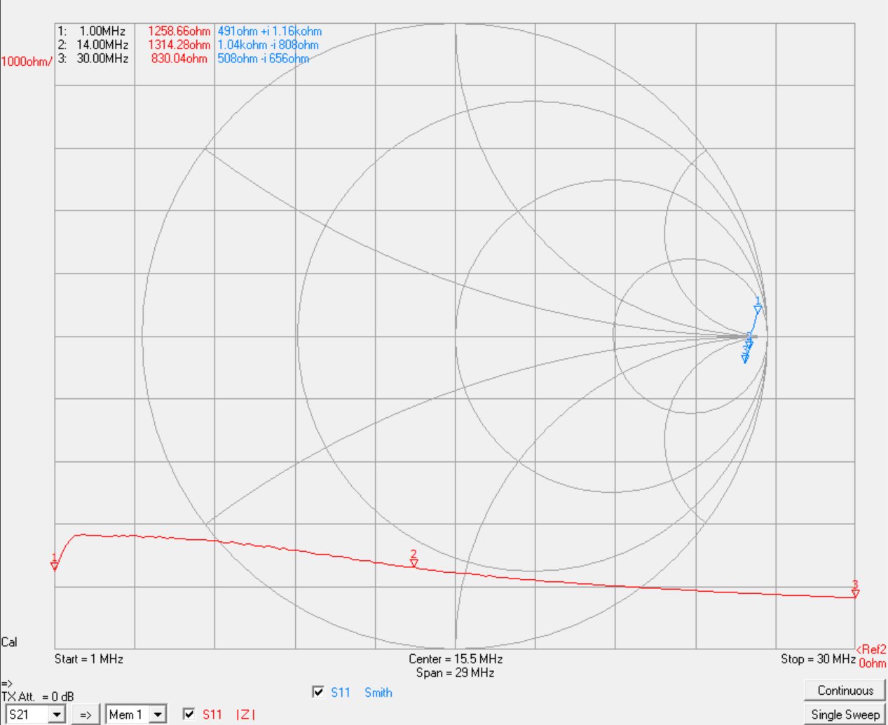
I attached a 25-ohm resistor at one end of the windings, and the VNA to the other, and made an S11 measurement, and it was not bad (it was slightly worse the first time, but I redid it with tighter twists). I suspect I still have not achieved 25-ohm characteristic impedance, which may be causing the slight degradation at higher frequencies.
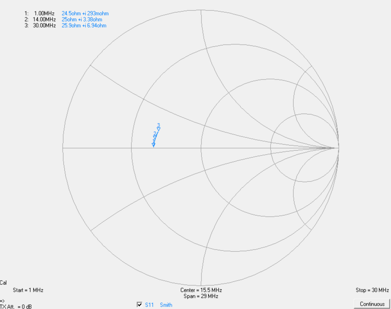
After this, although I now had an unbalanced interface, I still had the problem that the input impedance was 25 ohm, not 50!

Here's a photo of the balun (taken much later, after it was assembled into the complete system). You can see the four windings were quite tightly twisted together.
Impedance Transformation Sub-System
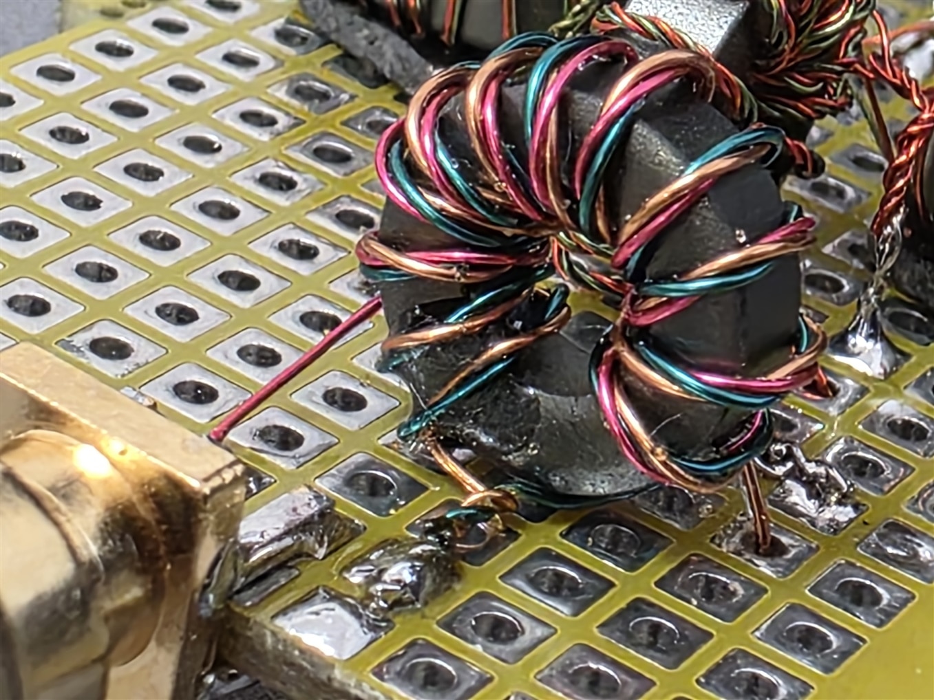
Referring again to literature, there’s a book by Sevick called Transmission Line Transformers, which details a variety of such transformers. One was particularly interesting (it is also in this PDF on page 40); it involves a trifilar winding, where one of the three windings stops early, 80 percent of the way through. I gave it a try; actually, a couple of tries, just like all the other steps in this project! and it worked remarkably well.
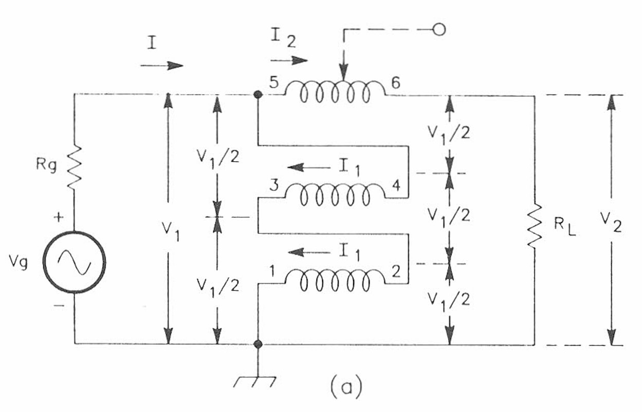
Image Source: Transmission Line Transformers by Sevick
To test it, I connected the 50-ohm side (the side with the tap at 80%) to a 50-ohm load. I connected the 25-ohm side to the VNA, and I expected to see 25 ohms being measured. The result was smeared slightly into the inductive half of the Smith chart at higher frequencies, but overall I thought it was very acceptable.
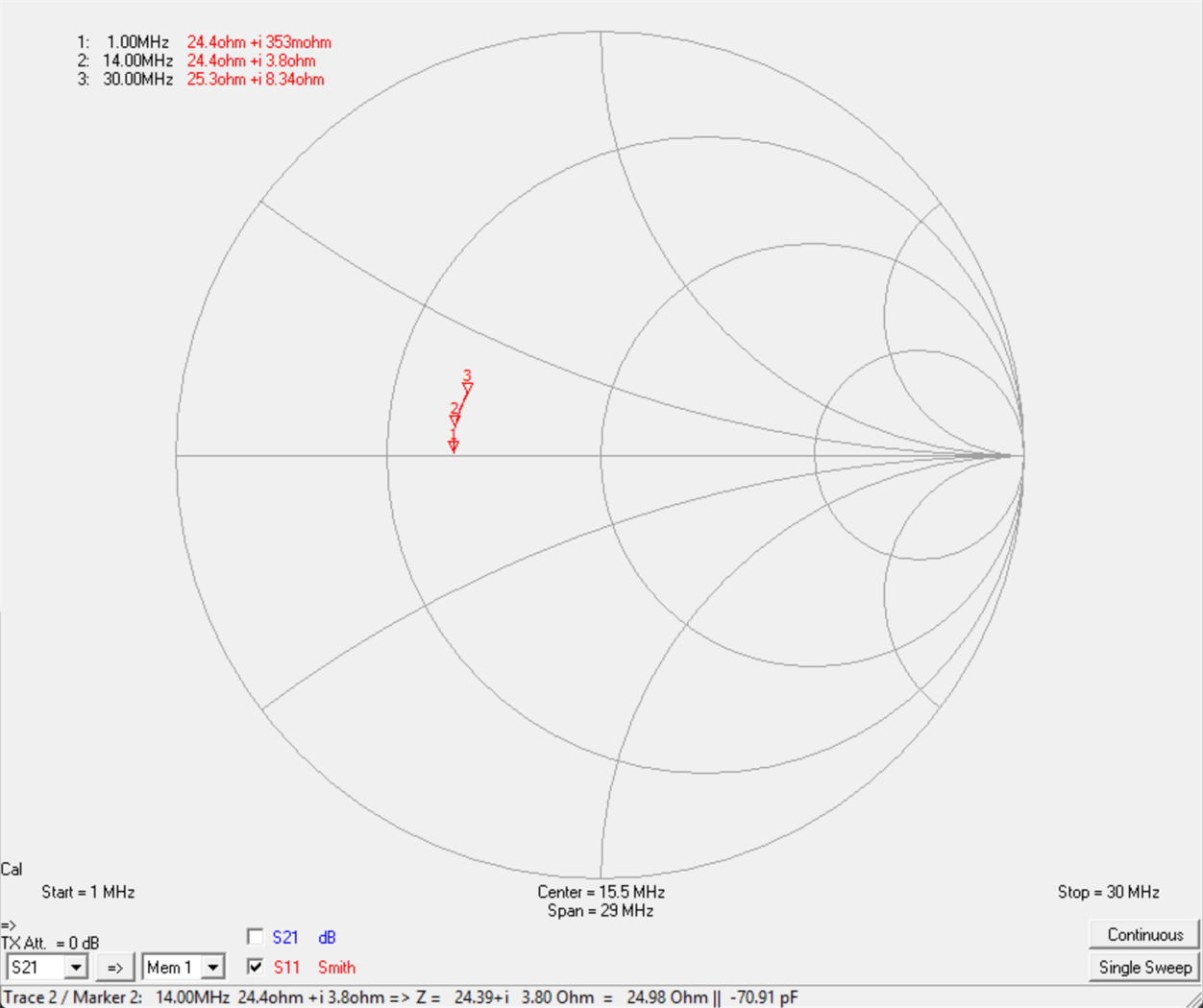
As another test, I wanted to see what the insertion loss would be so I removed the 50-ohm load and connected that to Port 2 of the VNA, so that the VNA could perform a S21 measurement. I forgot to take a screen capture, but the result was a near-flat 0.7 dB loss. However, 0.5 dB of that is expected to occur, simply because of the mismatch. Therefore the discrepancy from the expected result was just 0.2 dB.

Here's a closeup of the impedance transformer. The pink wire on the left side is the 80% tap connection.
Putting It All Together
The final circuit diagram of the entire system is shown below.

I assembled it up on a small piece of prototyping board which had a ground plane on the underside. Time to test it!
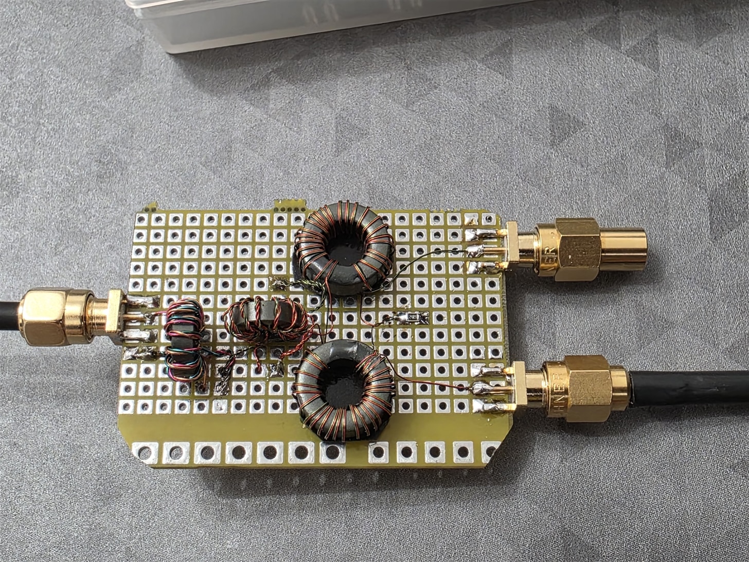
For a first test of the system, I attached 50-ohm terminations to both outputs, and then connected the input to the VNA. The result looked good to me.
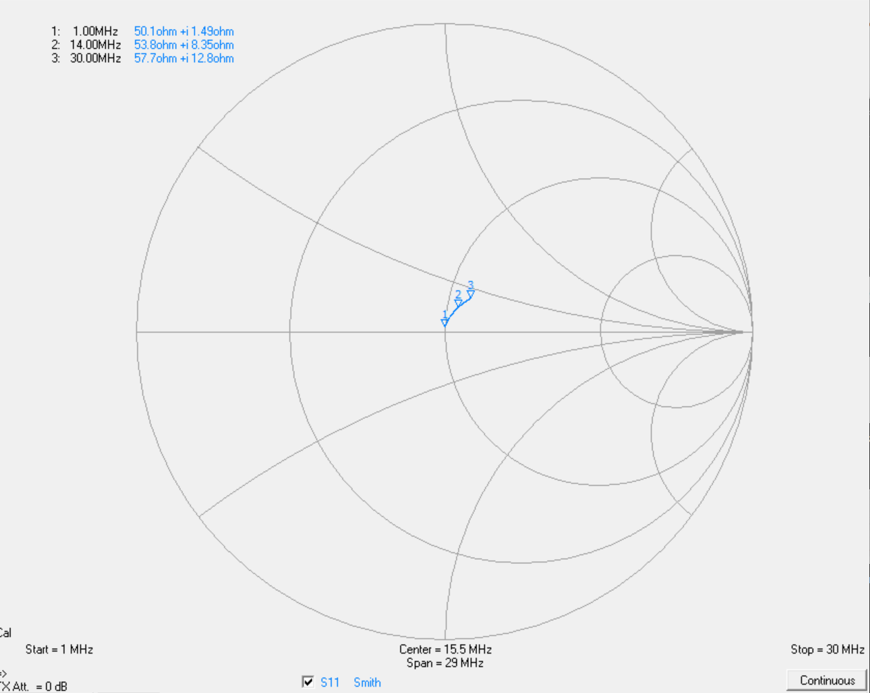
Next, I removed a terminator from one of the outputs, and attached the output to Port 2 of the VNA, and measured the insertion loss; it ought to be close to 3 dB. You can see the insertion loss show with the dark blue horizontal line in the screenshot below. Notice how good the S11 turned out, it’s almost a dot at the center of the Smith chart.

I repeated for the other output, which had very similar insertion loss. Notice the S11 measurement isn’t quite as good, but still acceptable. I think this shows that the two ferrites perhaps have to be wound extremely identically.

Results
Here’s an AI-generated table summarizing the results from my captures.
|
Freq (MHz) |
Out1 (dB) |
Out2 (dB) | Imbalance (dB) | Phase Err (deg) | Total Output Pwr (%) | Input SWR |
| 1 | −3.142 | −3.144 | 0.002 | 0.253 | 96.6 | 1.03:1 |
| 5 | −3.318 | −3.328 | 0.010 | 0.114 | 92.9 | 1.09:1 |
| 10 | −3.475 | −3.476 | 0.001 | 0.153 | 89.9 | 1.15:1 |
| 14 | −3.571 | −3.568 | 0.003 | 0.187 | 87.9 | 1.19:1 |
| 20 | −3.699 | −3.690 | 0.009 | 0.257 | 85.4 | 1.25:1 |
| 25 | −3.798 | −3.780 | 0.017 | 0.303 | 83.5 | 1.29:1 |
| 30 | −3.892 | −3.864 | 0.028 | 0.386 | 81.9 | 1.32:1 |
How does this compare to a commercial splitter?
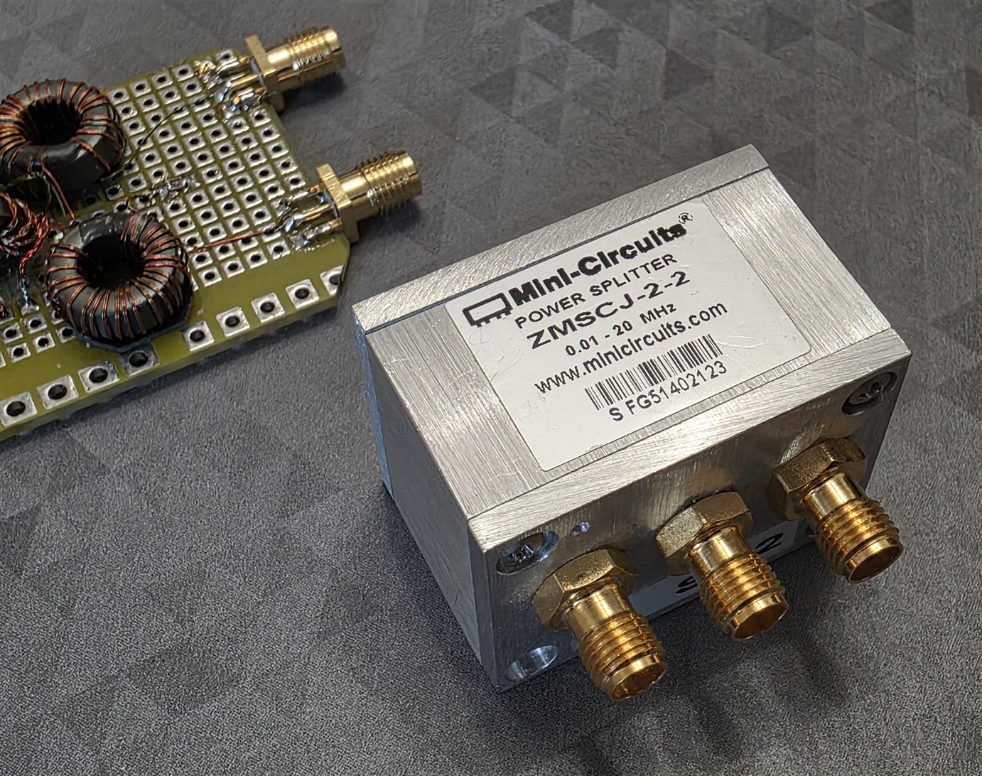
I have a Minicircuits ZMSCJ-2-2 which costs over £100/$100 these days. Compared to that, the DIY version covers a broader range, and the phase error is lower. However, importantly, the Minicircuits version has a slightly lower typical insertion loss (although the specified maximum is not much different to what the DIY version achieved, and, up to 5 MHz or so, there is lower loss with the DIY version compared to the Minicircuits version typical value). With a bit more experimentation there's no reason why it shouldn't be able to be improved further.
Summary
For a fraction of the cost (a few $ versus over $100) a DIY power splitter was created using type 77 ferrites and a VNA. The steps to make this particular splitter involved creating baluns, impedance transformers, and the multi-coil hybrid system that actually does the splitting action. Each of these subsystems were tested independently before joining them together.
The resulting performance I think is well worth the effort, and I believe it would be better on a second attempt, having learned the importance of trying to have consistent windings, and making the time to experiment more than I have done, to get even better performance out of each subsystem.
For more articles about VNAs and some of the topics that were in this blog post, here are some links, but there is a wealth of other info on the site covering all the topics too:
(+) Why are Ferrites needed in Electronic Devices? - element14 Community
(+) Low-cost Vector Network Analyzer: NanoVNA-H4 Unboxing - element14 Community
(+) FPC1500 Spectrum Analyzer - Review - element14 Community
(+) Understanding Guanella Components (Baluns) - element14 Community
Thanks for reading!