element14 Community
element14 Community
    Register Log In
  • Site
  • Search
  • Log In Register
  • About Us
  • Community Hub
    Community Hub
    • What's New on element14
    • Feedback and Support
    • Benefits of Membership
    • Personal Blogs
    • Members Area
    • Achievement Levels
  • Learn
    Learn
    • Ask an Expert
    • eBooks
    • element14 presents
    • Learning Center
    • Tech Spotlight
    • STEM Academy
    • Webinars, Training and Events
    • Learning Groups
  • Technologies
    Technologies
    • 3D Printing
    • FPGA
    • Industrial Automation
    • Internet of Things
    • Power & Energy
    • Sensors
    • Technology Groups
  • Challenges & Projects
    Challenges & Projects
    • Design Challenges
    • element14 presents Projects
    • Project14
    • Arduino Projects
    • Raspberry Pi Projects
    • Project Groups
  • Products
    Products
    • Arduino
    • Avnet Boards Community
    • Dev Tools
    • Manufacturers
    • Multicomp Pro
    • Product Groups
    • Raspberry Pi
    • RoadTests & Reviews
  • Store
    Store
    • Visit Your Store
    • Choose another store...
      • Europe
      •  Austria (German)
      •  Belgium (Dutch, French)
      •  Bulgaria (Bulgarian)
      •  Czech Republic (Czech)
      •  Denmark (Danish)
      •  Estonia (Estonian)
      •  Finland (Finnish)
      •  France (French)
      •  Germany (German)
      •  Hungary (Hungarian)
      •  Ireland
      •  Israel
      •  Italy (Italian)
      •  Latvia (Latvian)
      •  
      •  Lithuania (Lithuanian)
      •  Netherlands (Dutch)
      •  Norway (Norwegian)
      •  Poland (Polish)
      •  Portugal (Portuguese)
      •  Romania (Romanian)
      •  Russia (Russian)
      •  Slovakia (Slovak)
      •  Slovenia (Slovenian)
      •  Spain (Spanish)
      •  Sweden (Swedish)
      •  Switzerland(German, French)
      •  Turkey (Turkish)
      •  United Kingdom
      • Asia Pacific
      •  Australia
      •  China
      •  Hong Kong
      •  India
      •  Korea (Korean)
      •  Malaysia
      •  New Zealand
      •  Philippines
      •  Singapore
      •  Taiwan
      •  Thailand (Thai)
      • Americas
      •  Brazil (Portuguese)
      •  Canada
      •  Mexico (Spanish)
      •  United States
      Can't find the country/region you're looking for? Visit our export site or find a local distributor.
  • Translate
  • Profile
  • Settings
Test & Tools
  • Technologies
  • More
Test & Tools
Forum MULTICOMP PRO MP750065 Function Generator - 1st impressions
  • Blog
  • Forum
  • Documents
  • Files
  • Members
  • Mentions
  • Sub-Groups
  • Tags
  • More
  • Cancel
  • New
Join Test & Tools to participate - click to join for free!
Actions
  • Share
  • More
  • Cancel
Forum Thread Details
  • Replies 31 replies
  • Subscribers 354 subscribers
  • Views 10011 views
  • Users 0 members are here
  • MP750065
  • arbitrary
Related

MULTICOMP PRO MP750065 Function Generator - 1st impressions

Jan Cumps
Jan Cumps over 3 years ago

Since yesterday, I have a MP750065  function generator and counter.

image

Specs:

  • DC to 5 MHz
  • 1 µHz resolution
  • 5 Vpp in 50Ω (10 Vpp in high impedance)
  • sine, pulse and flank (triangle)
  • variable duty cycle for pulse. For the other two waveforms this function changes the symmetry
  • Sweep linear and Log, start, end and speed are configurable
  • AM and FM modulation, with external input
  • Sync output, can be used to trigger an oscilloscope while sweeping
  • arbitrary waveforms, 20 preloaded. 20 custom waves can be stored
  • power output that can drive 4W, with a 200 kHz upper limit.
  • counter up to 100 MHz
  • USB, remote software

Unexpected specs:

  • it's SCPI programmable. This is not mentioned on the e14 shops, but a great feature
  • the OEM is UNI-T. This device is the twin of the UTG900C-II

First Use 

The basic functionality is easy to use: switching the traditional wave forms, frequency, amplitude. Even duty cycle.
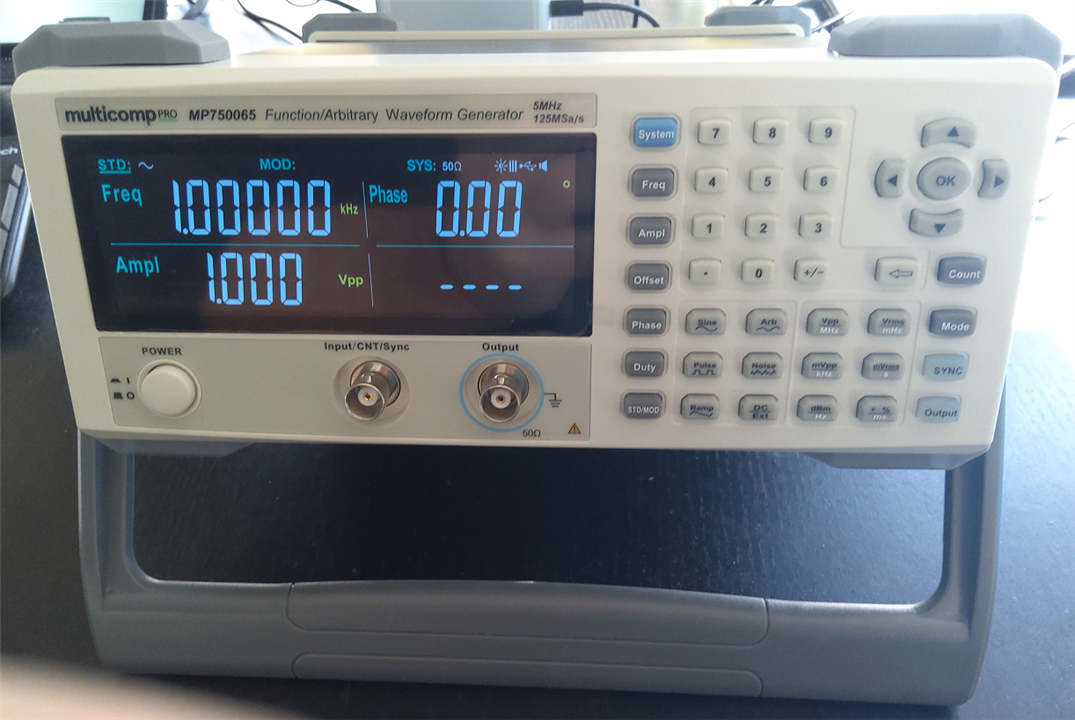
I got started with the instrument in minutes. It shows a default waveform when switching the device and output on. A 1 kHz, 100 mVpp (in 50Ω) sine wave.
Because the popular parameters can be set with function keys, altering that form just works as you'd expect it to.

A few other functions, such as the output impedance switch from high to 50Ω were less intuitive, but I found how to do that without reading the manual too.
Once you go to the more advanced functions, like sweep setup, you'll need the manual the first few times. It's not difficult, but they require that you know the steps.

I haven't used the arbitrary functionality or the counter yet.

Teardown

(I did a more detailed teardown in a later post)

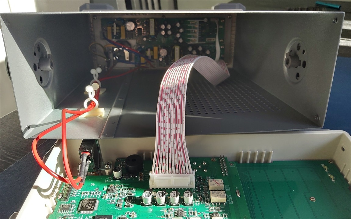
I took a look inside. Mainly two sections: power supply at the back, Instrument and user interface up front. The middle of the box is empty.
To remove front and back, you pull the baby bumpers on both sides. There's a screw under each of them. The connection point of the bumpers is near the end. Releasing and re-fixing them is easy and requires little force.


image

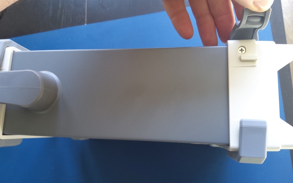
You can then carefully pull both ends of the instrument from the housing. If you disconnect a few cables, you can remove them fully. I haven't done that.

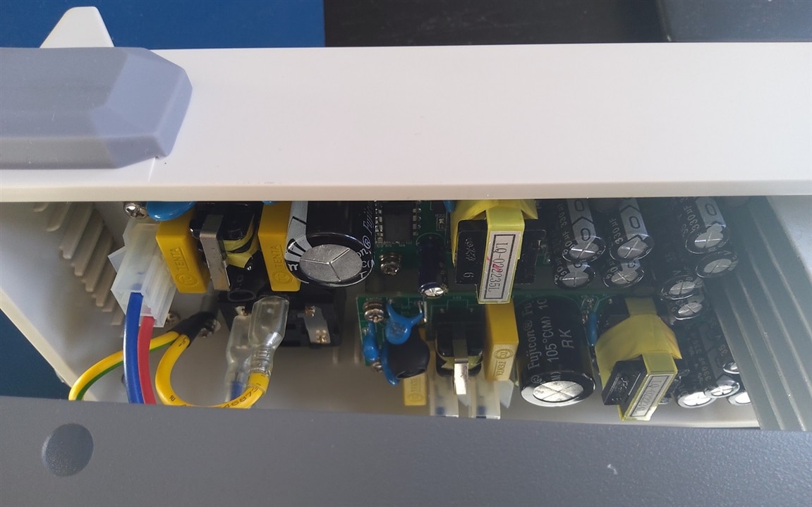
Here are a few photos of the PSU at the back:

image

image

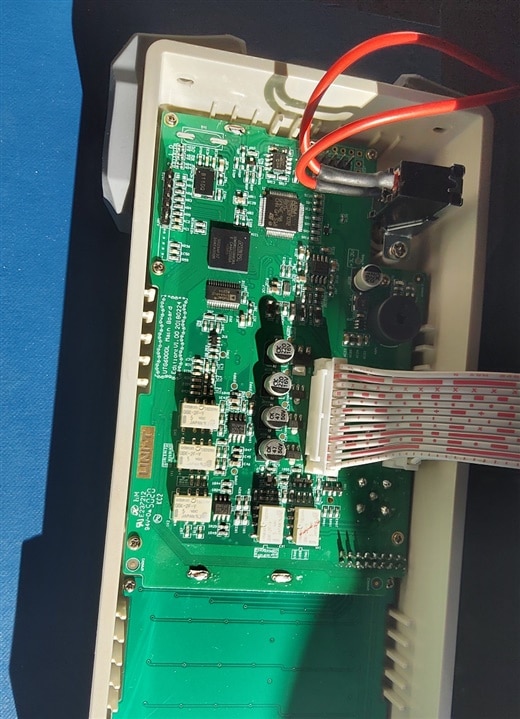
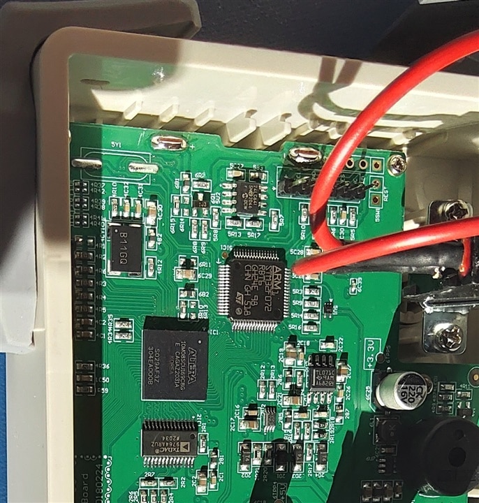
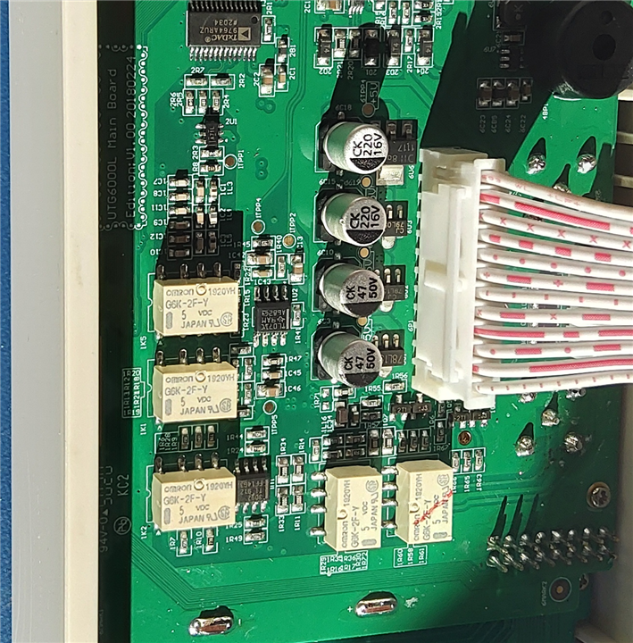
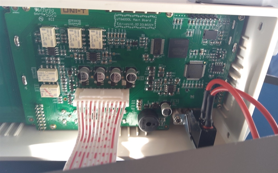
… and some of the instrument side. Spot the ARM and FPGA.

image

image

image

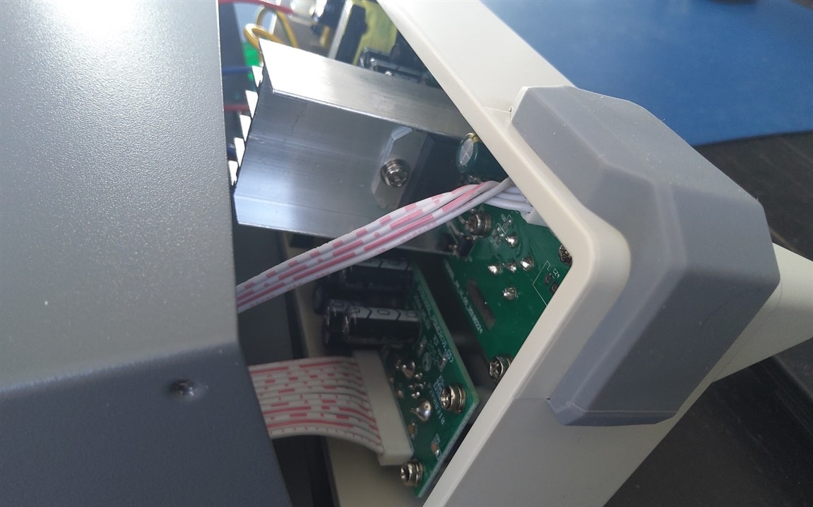
The next one is unsharp. I added it because it gives a good impression of the front panel's backside.

image

Finally, a peek inside the box:

image

One of the things I learned while peeking inside, is that the PCB had a type number mechanism typically used by UNI-T.
Knowing that MULTICOMP PRO uses OEMs, I went to look online to find the matching model. It's the UTG9000C-II.
It has the identical looks, specs and user documentation. But also a programmer's guide that's not available on AVNET's shops.
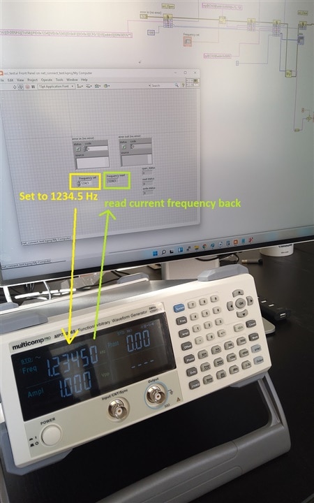
There I found that this device should be SCPI controllable. I'll test this out with LabVIEW at a later time.

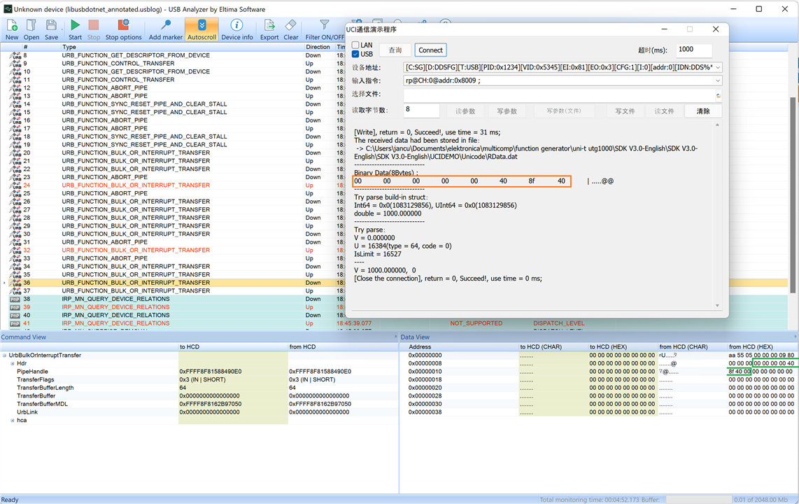
edit after investigation: it is LabVIEW programmable - but not your typical NI-VISA and SCPI approach. It automates well though.

You don't have permission to edit metadata of this video.
Edit media
x
image
Upload Preview
image

Thank you for reading.

Related blog:

MULTICOMP PRO MP750065 Function Generator - 1st impressions
Programming Pt1: SDK Demo
Programming Pt2: LabVIEW tryout (a)
Programming Pt3: LabVIEW tryout (b)
Programming Pt4: LabVIEW Driver Lib Init block
Programming Pt5: LabVIEW Driver Lib Read, Write and Close blocks
Programming Pt6: LabVIEW Driver Lib: High Level Functional blocks
Repair and teardown
  • Sign in to reply
  • Cancel

Top Replies

  • scottiebabe
    scottiebabe over 3 years ago in reply to Jan Cumps +3
    I have had similar experiences with the MP750668 which is *very* similar to the UTG1010. None of the included software functioned, but I did manage to talk to the instrument with uni-t SDK demo applic…
  • michaelkellett
    michaelkellett over 3 years ago +2
    Nice first look Jan. Interesting to see it's a TxDAC AD9764 from Analog, 14 bit 125Ms/s part and the FPGA is a pretty simple ALtera Max10 part. and a fairly light weight ARM M0 with 16kRAM on chip -…
  • shabaz
    shabaz over 3 years ago +2
    Hi Jan, Looks like there's no fan, completely silent? I saw your review appear in my e-mails earlier today (approx 10 hours ago), but when I look at the Recent Content just now, I don't see this blog…
Parents
  • michaelkellett
    michaelkellett over 3 years ago

    Nice first look Jan.

    Interesting to see it's a TxDAC AD9764 from Analog, 14 bit 125Ms/s part and the FPGA is a pretty simple ALtera Max10 part. and a fairly light weight ARM M0 with 16kRAM on chip - nothing exotic here at all.

    Very good news re. programming - I look forward to seeing how you get on with programming it.

    MK

    • Cancel
    • Vote Up +2 Vote Down
    • Sign in to reply
    • Cancel
  • Jan Cumps
    Jan Cumps over 3 years ago in reply to michaelkellett
    michaelkellett said:
    Very good news re. programming - I look forward to seeing how you get on with programming it.

    success. I've been able to set the instrument and read back.
    Action photo showing the LabVIEW screen and instrument - real setup:

    image

    It takes the frequency set in the left control, programs the device, then reads the set frequency back from the device and displays it in the right control.

    • Cancel
    • Vote Up +1 Vote Down
    • Sign in to reply
    • Cancel
Reply
  • Jan Cumps
    Jan Cumps over 3 years ago in reply to michaelkellett
    michaelkellett said:
    Very good news re. programming - I look forward to seeing how you get on with programming it.

    success. I've been able to set the instrument and read back.
    Action photo showing the LabVIEW screen and instrument - real setup:

    image

    It takes the frequency set in the left control, programs the device, then reads the set frequency back from the device and displays it in the right control.

    • Cancel
    • Vote Up +1 Vote Down
    • Sign in to reply
    • Cancel
Children
  • michaelkellett
    michaelkellett over 3 years ago in reply to Jan Cumps

    I've been following your efforts and admire your persistance.

    For my purposes LabView isn't an option.

    My preference for USB interfaces (for this type of instrument) would be SCPI or similar over pseudo COM port.

    I took a quick look at the USBTMC spec but it would be a lot of work to implement ones own driver. Some private ones seem to exist, even written in my software tool of choice (Xojo) but not open source.

    MK

    • Cancel
    • Vote Up +1 Vote Down
    • Sign in to reply
    • Cancel
  • Jan Cumps
    Jan Cumps over 3 years ago in reply to michaelkellett

    I think that if I had a USB sniffer, I'd be able to complete the original exercise I did.

    I tried the software USB analyser way,  with a trial edition of USBlyzer, but once I installed it and rebooted, no USB device on my laptop worked anymore. 
    After a moment of panic and despair, I uninstalled that software, rebooted again and  my mouse, keyboard, etc... started working again.
    Dodged a bullet there - but it also mean that I can't capture the low level communication at the Windows side.

    I'm fairly confident that I have the USB device open, reader and writer correctly allocated. But don't know how a correct exchange looks like on that level.
    It's definitely not just sending the same commands as in the programming guide.

    I could apply a USBSerial and a USBTMC driver to the device, but again never could engage in a meaningful conversation.

    • Cancel
    • Vote Up +2 Vote Down
    • Sign in to reply
    • Cancel
  • Jan Cumps
    Jan Cumps over 3 years ago in reply to Jan Cumps

    ... just tried with an other USB analyser: USB Analyzer by Eltima Software. A 14 day trial.
    That one works and doesn't render my devices defunct.

    Long story short: the data transfer is complex. nothing ASCII floating back and forth.
    If you're interested in what's happening at low level: I attached a zip file with the analyser's log and a text file indicating what command matches to what log entries.

    libusbdotnet_usb_analuzer.zip

    In the capture below, I selected a particular log record because I recognise the data returned from a read operation:

    image

    I'm not going to this road. Leaving it here if it helps when the DLL approach doesn't fit the scenario.

    • Cancel
    • Vote Up +2 Vote Down
    • Sign in to reply
    • Cancel
element14 Community

element14 is the first online community specifically for engineers. Connect with your peers and get expert answers to your questions.

  • Members
  • Learn
  • Technologies
  • Challenges & Projects
  • Products
  • Store
  • About Us
  • Feedback & Support
  • FAQs
  • Terms of Use
  • Privacy Policy
  • Legal and Copyright Notices
  • Sitemap
  • Cookies

An Avnet Company © 2025 Premier Farnell Limited. All Rights Reserved.

Premier Farnell Ltd, registered in England and Wales (no 00876412), registered office: Farnell House, Forge Lane, Leeds LS12 2NE.

ICP 备案号 10220084.

Follow element14

  • X
  • Facebook
  • linkedin
  • YouTube