At the start of the challenge I had just a bit of knowledge about flyback transformers and converters from briefly exploring them in class, but from the day i saw the challenge announcement, it piqued my interest and my curiosity went all in into researching this very fascinating subject.
As I mentioned in the first blog, Power electronics was a scary thing to explore; many capacitors have been incapacitated by my faulty prototypes, many resistors have found they just can't resist anymore, and many transistors have -insert a transistor related euphemism for "exploded" here-. So writing something that could help newcomers not feel scared about it became my goal for the challenge.
I also learned many new things thanks to my constant reading on the topic since day one, and thanks to the other challengers' blogs and their comments on mine that knowledge was expanded even further.
There are still many things about flybacks that I think are interesting enough to keep writing about, and I'm sure even more to discover and read about! So after a break from all that's happened in the past couple of weeks around the contest, I'll periodically continue to add new content around this technology.
But for now, let's take a look at what was accomplised:
I started this adventure by asking the question:
Does it fly back?
I knew the first blog needed to be interesting, so I quickly showed the kit:
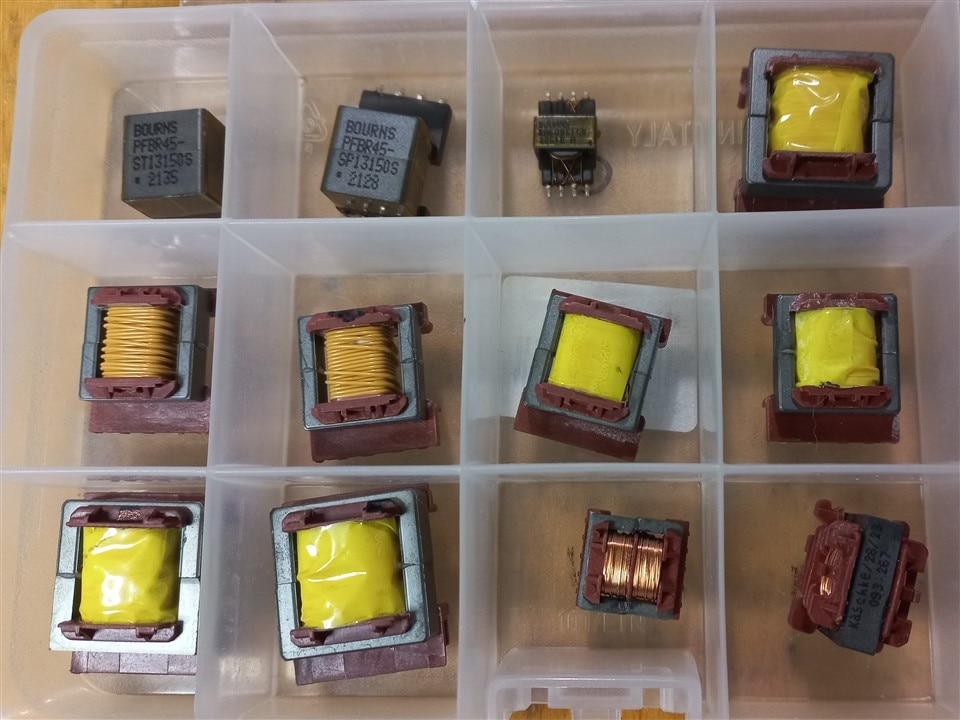
and picked the easiest to work with out of the lot:
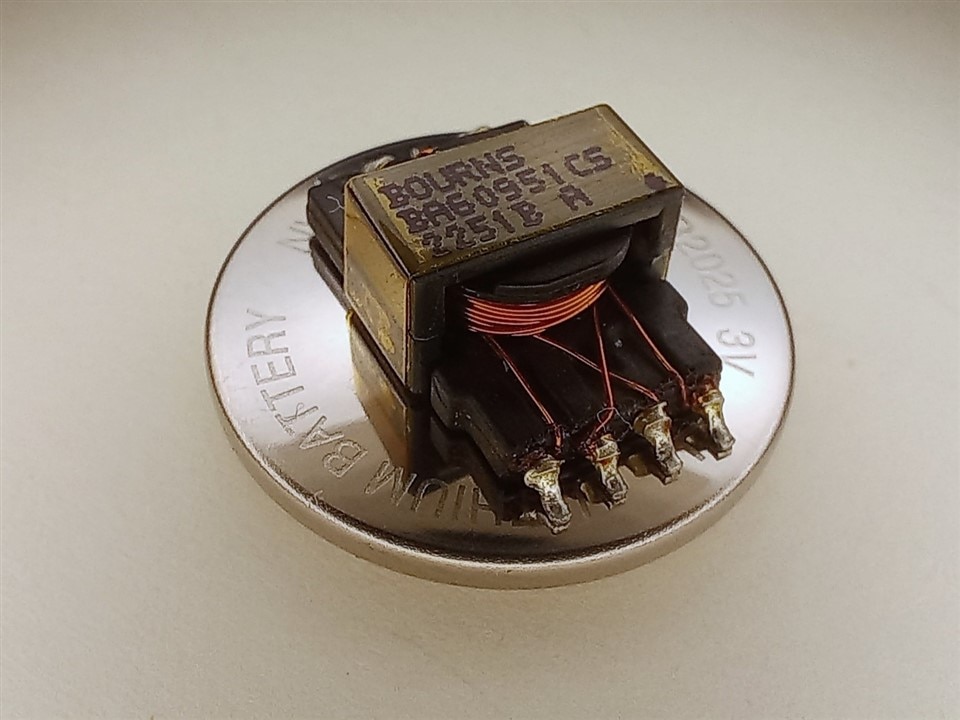
I almost couldn't believe how tiny it was, and didn't imagine how easy to work with it would be.
What has been a theme in my electronics journey also became part of the challenge: the simulations. I think that even if they are not as hands on as the physical objects all the components we work with are, they are an amazing tool, useful to teach, to learn, and at least also to get an idea if your circuit will work, or how it is likely to work. Simulations, simulations, simulations!
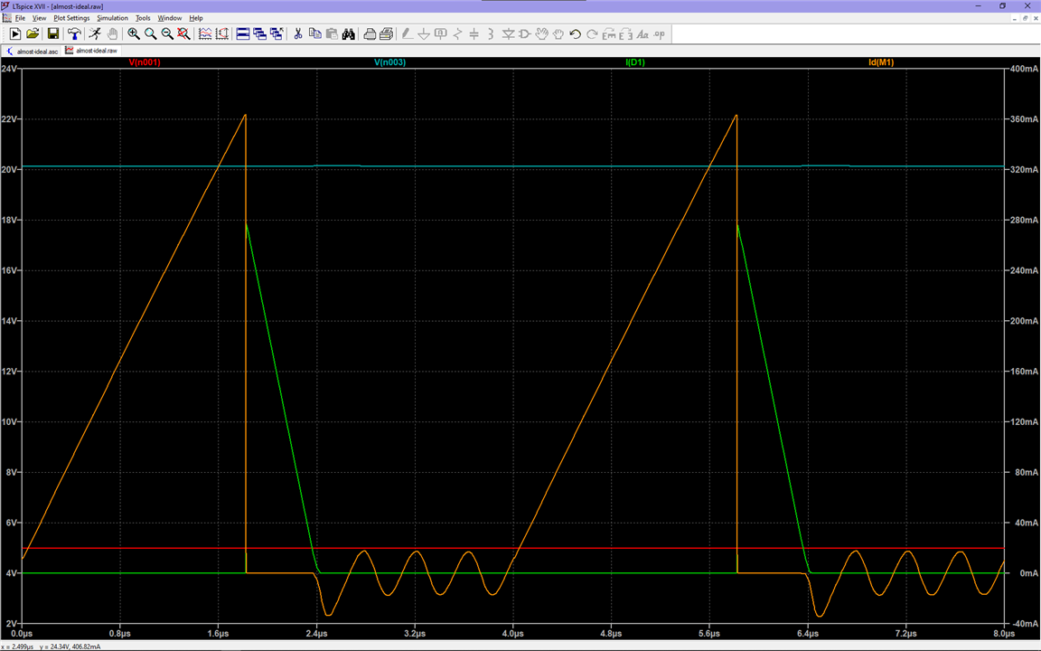
This was a taste of what was to come, both to real life and to future simulations. Here we saw how the currents in a flyback converter might look like, and was the start of becoming familiar with the topology:
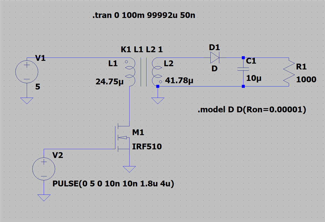
Then the circuit was built:
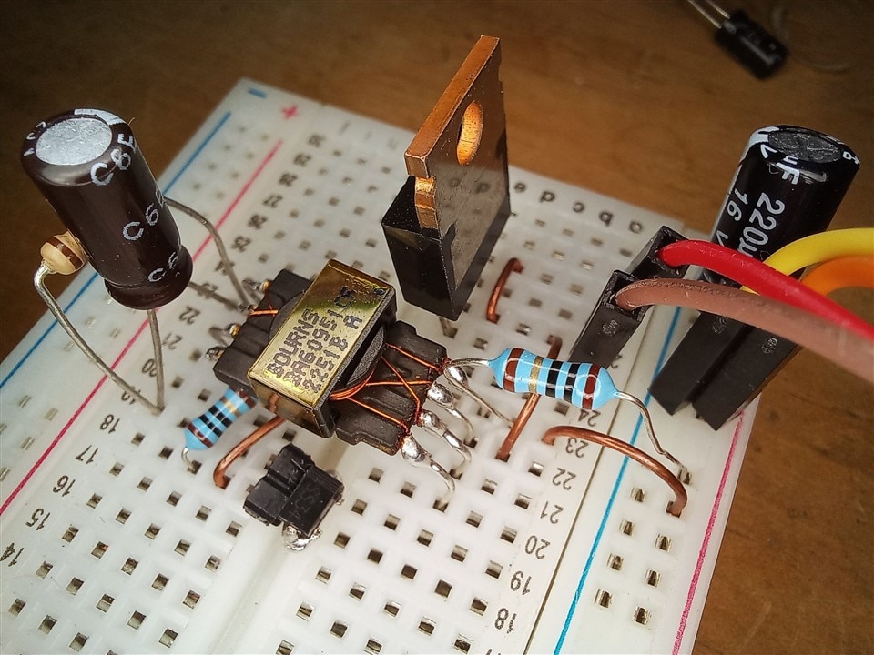
And thanks to more realistic simulations, we were prepared to see it behaving like this:
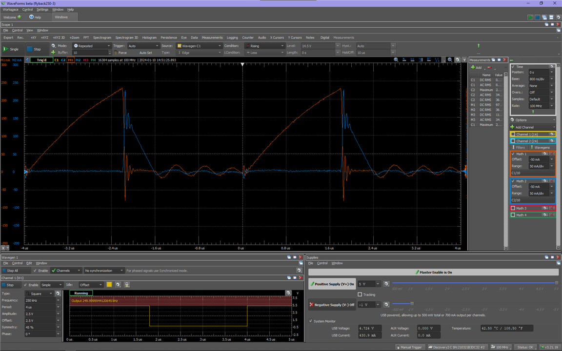
Covering the math behind all this also felt really important, as a strong theoretical foundation would make the journey much more relaxed.
But the equations didn't tell us anything about this bad boy squiggle over here:
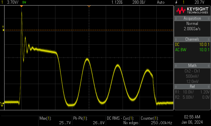
So this was the opportunity to research about this phenomenon and begin working on the next blog.
Ring ring!? Not today!
I knew this one was going to be a bit more tedious to go through than the previous one. Now we were going deeper and covering a subcircuit that would become an integral part of our converter: the snubber network. It was no longer about having a converter up and running, but about having it running nicely, to ensure all its components were satisfied in their environment. This, of course, required more theory, simulations, and math than the previous one. We now cared about operating modes and how the flyback cycle worked.
I mentioned that the main operating modes were CCM and DCM, but there are many more! I could not properly cover more than one, or even that one. While i chose to focus on DCM, there were things left unmentioned, heard of zero voltage switching? Yeah, that's a thing!
So this blog being heavier on the theoretical side of things, I decided to start with a joke:

I ran this joke through friends and various things happened, some thought it was quite funny, another one wanted to pretend they didn't see it, and most curious of all responses, one of them went on to write fan fiction about detective snubber. I haven't read it yet, but I hear it seriously embraces the silliness, and I think that might be an understatement. Anyway...
So the flyback cycle was explained:
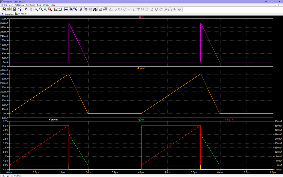
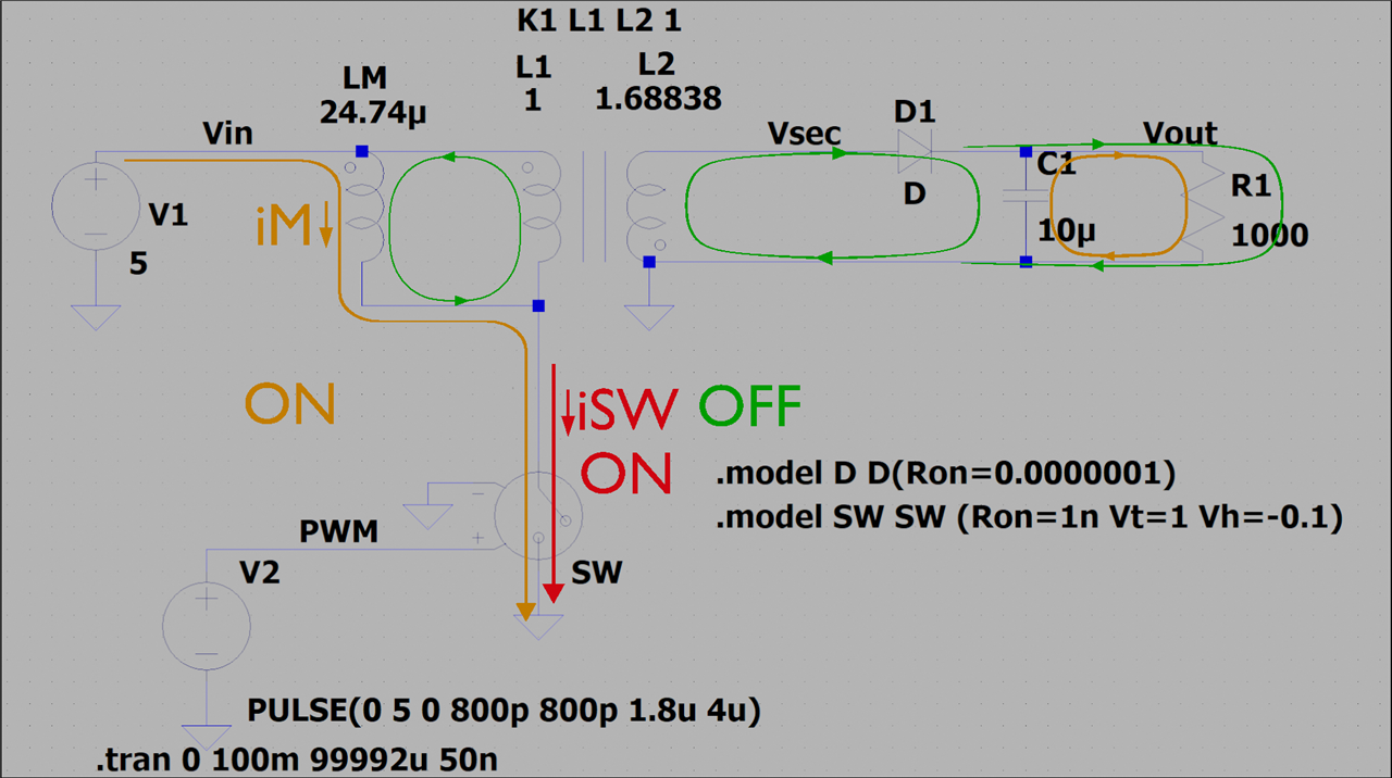
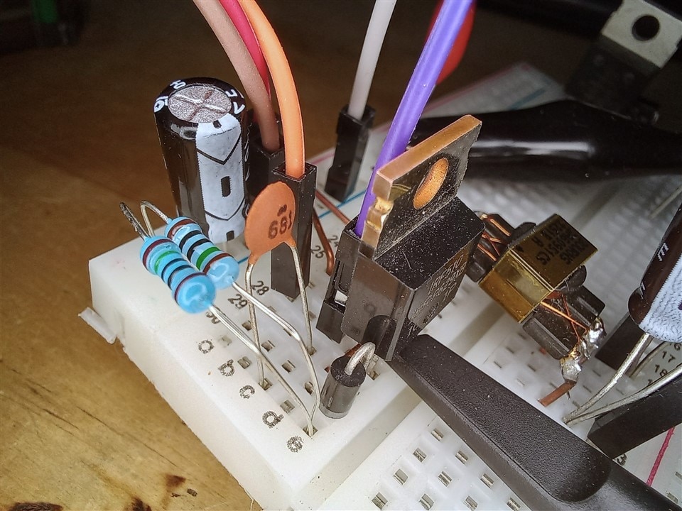
And a snubber circuit was built:
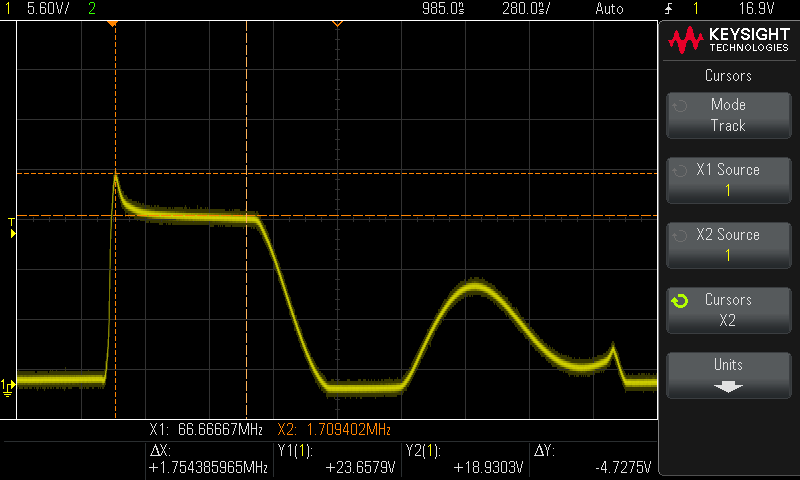
And things were much improved:
I thought I was going to end with just the practical example, but I couldn't resist running one more simulation, just to check everything was right and this improvement wasn't the result of an unexpected anomaly:
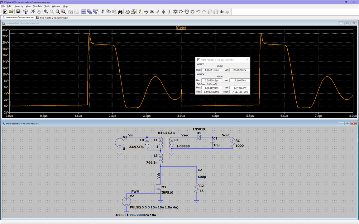
This revealed that while what was covered in the blog did indeed add up, there was still something unaccounted for:
Zener clamps and moving forward
At this point I was starting to actually have dreams about flyback converters. If I wasn't dedicated enough during the previous months, I was full into this, thinking about flyback jokes, how I would name the transformers, how is detective snubber doing in my friend's fanfic, will the zener clamp become its loyal partner?
I was a fan of Biricha, Sam Ben-Yaakov and katkimshow, rewatching their videos on loop, doing the math alongside them, hoping I was writing something of use, that I was able to transmit the knowledge I'd gained to others, and that I was making it entertaining.
It was also around here that it felt my goal of covering the basics of flyback converters was reaching its end, and I was fearing it may have been too basic, or perhaps too far from it!
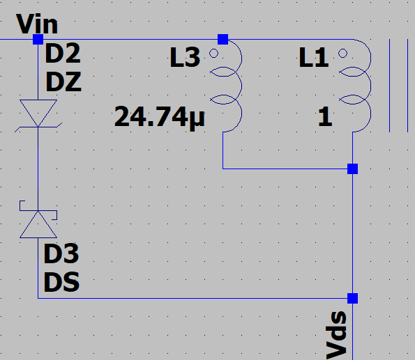
So this clamp subcircuit came into the picture:
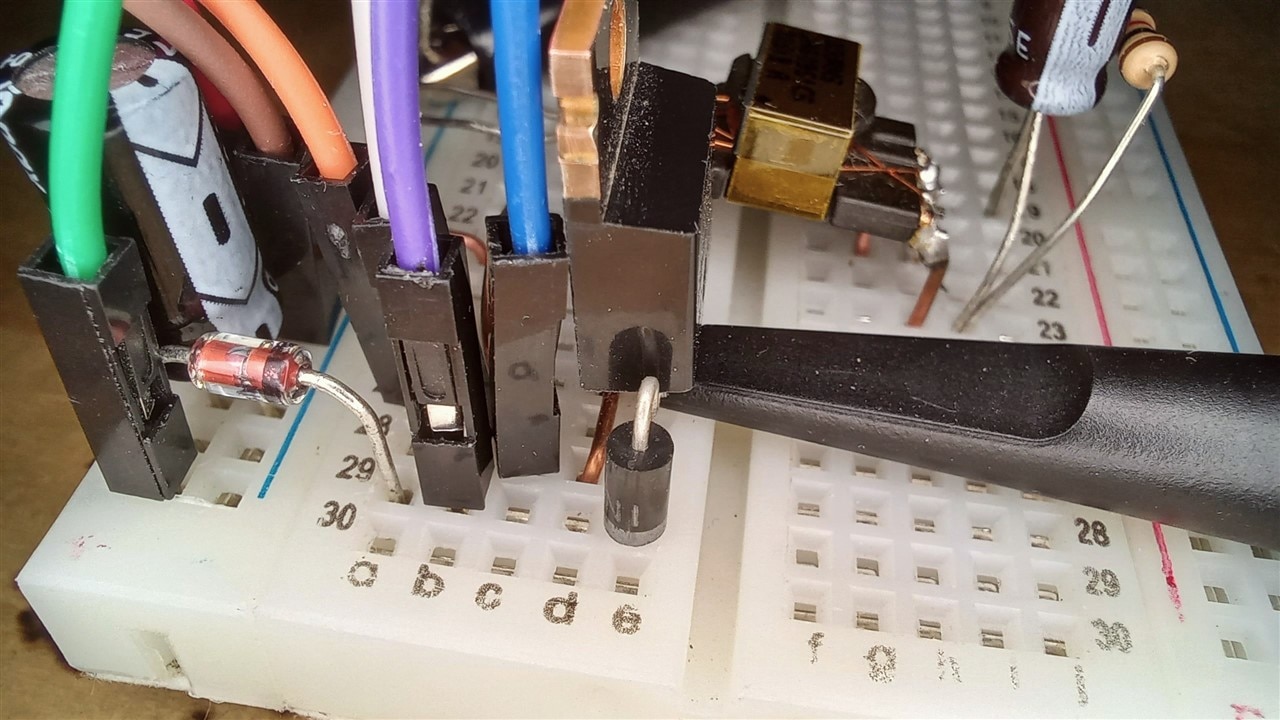
And it also came to reality!
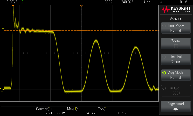
Doing a good job!
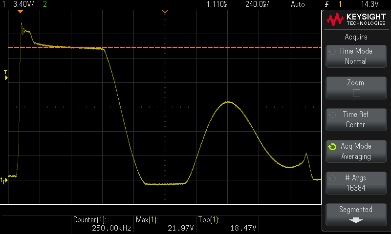
Its partnership with snubber was flourishing!
Having been looking at the voltage across the switch so much, it was now time to also see how the output voltage looked like, what did the converter actually do, arguably the most important voltage in a flyback converter, the actual reason we build such circuits for, to provide us with a different voltage from that which is supplying it:
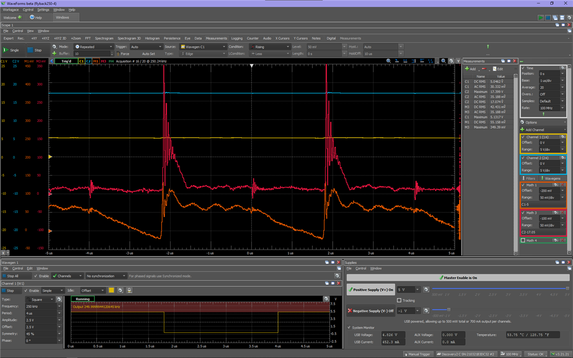
Looking at the output voltage at this point was great, cause it looked extremely noisy, unacceptable for many use cases! But we were now equipped with tools to improve this. The zener clamp and snubber subcircuits performed functions other than to keep the MOSFET happy. It also helped keep the device the converter was powering happy, and also helped keep the supply powering the converter happy! All a big happy family thanks to that pair of subcircuits.
Now that we could get DCM under control, it felt right to show the other main operating mode, CCM:
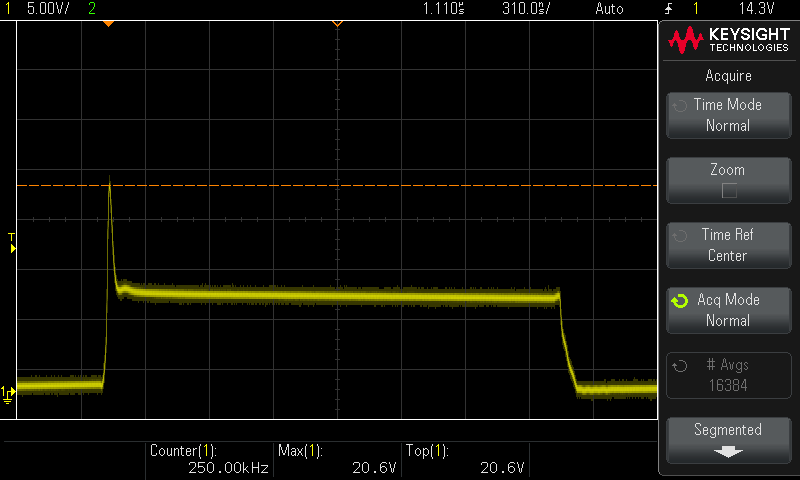
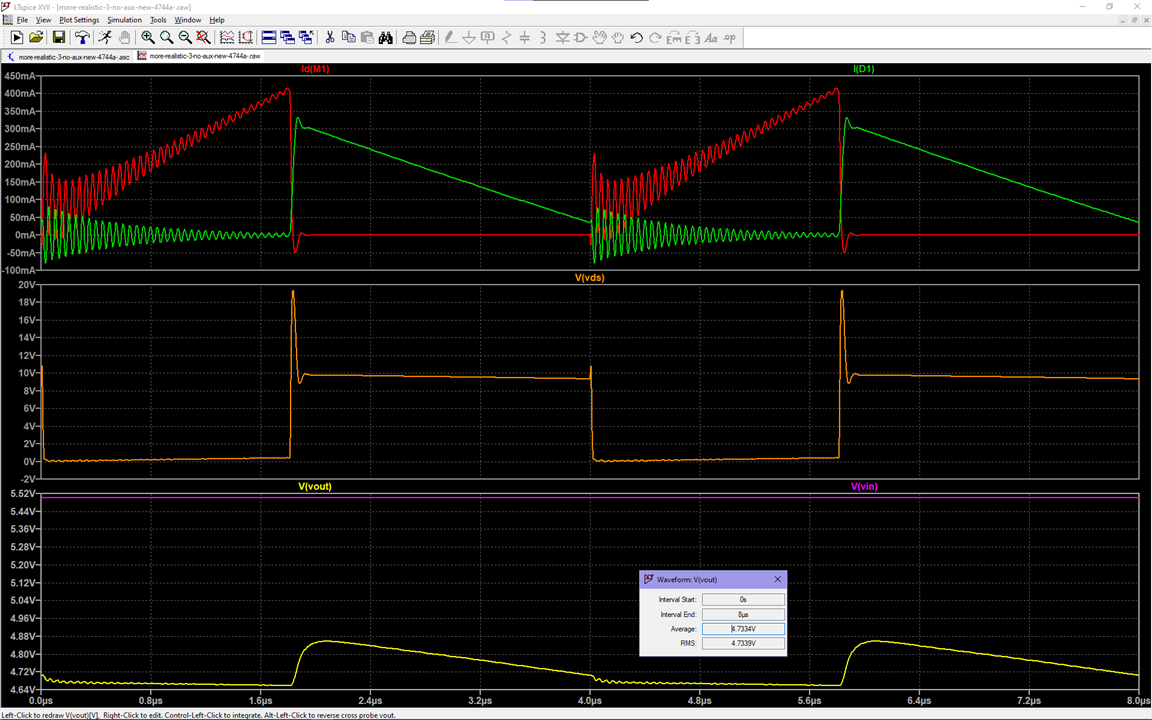
With this I also showcased the versatility of the topology. We could switch between operating modes as needed! Simulations, of course, continued to be helpful, showing a match for that Vds waveform, and giving us a look into the currents now that the training wheels had been removed (the 10 ohm resistors shown in the first blog):
And as that came to an end, the task of checking the other components became more pressing, so I started with mentions
Of common mode chokes and other transformers
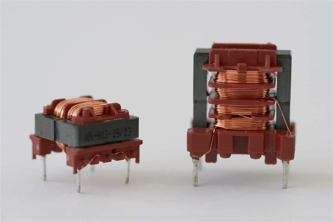
I thought I was prepared for this. I had experimented with these back in december:
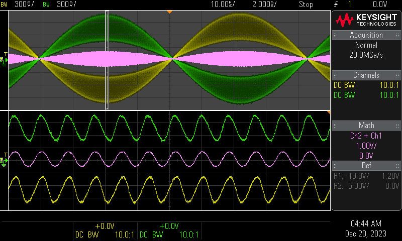
I mistakenly thought I understood EMC filtering as much as one could, it would be a piece of cake, no need to worry reading more about it. Well, I was horribly wrong, while yes, the topology is simple enough to get something out of it with random components, it is not as easy as i thought it would be to thoroughly go through the design and testing process, so I just built a circuit, and showed it in action:
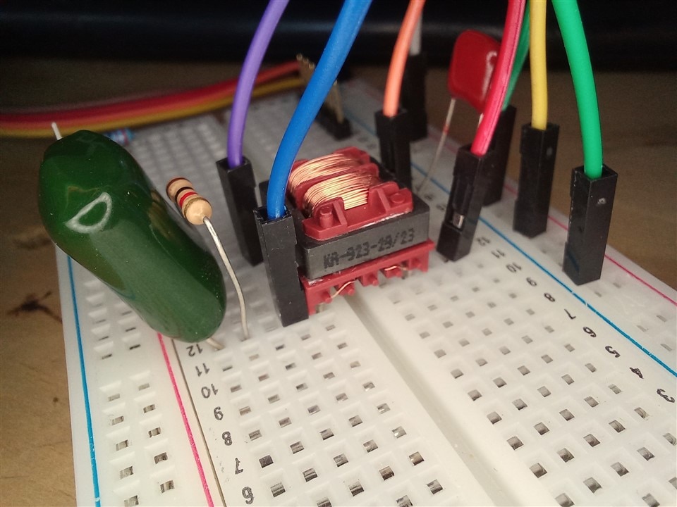
But I didn't understand it well enough to dare try to explain it, hence no math on that blog.
I also briefly covered the PLC transformers, and didn't perform any experiments with them:
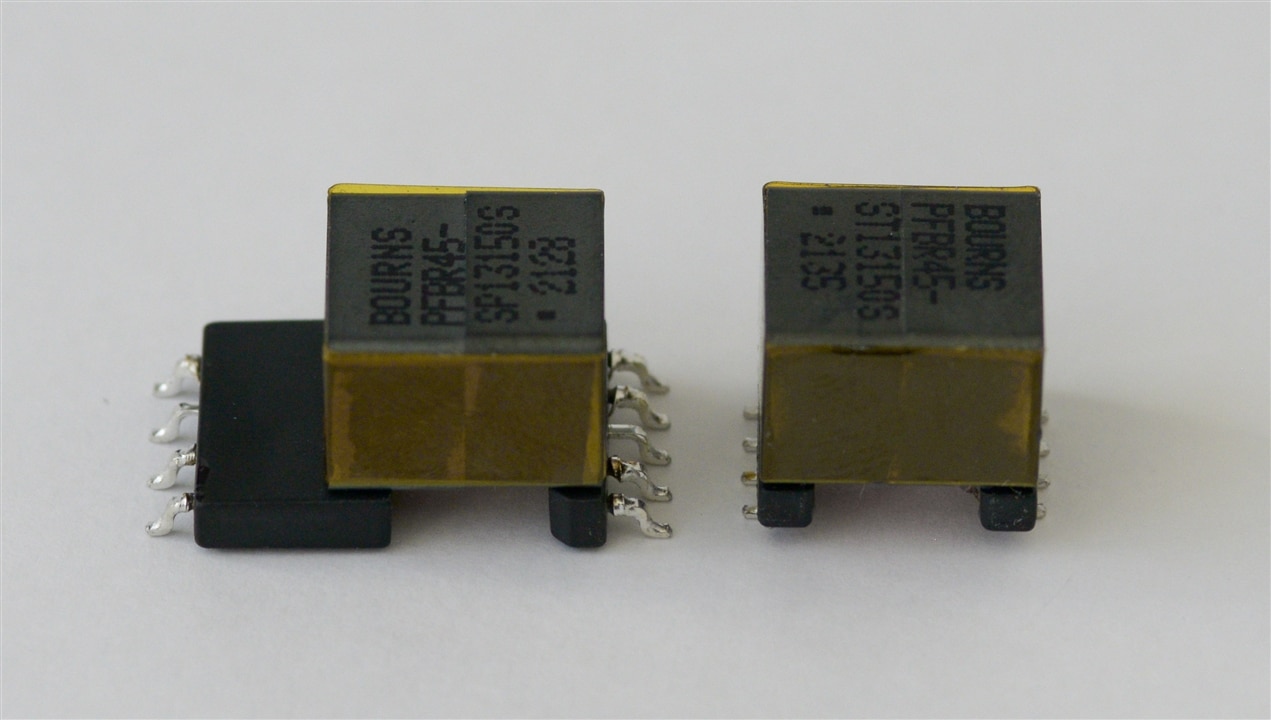
It was a cold ending to the blog, and so I moved forward, time to show the
Application description and part selection
I was under the impression that the final blog must be a final project and not a summary, so what I did on blog 5 was showing what I would work on for the final:
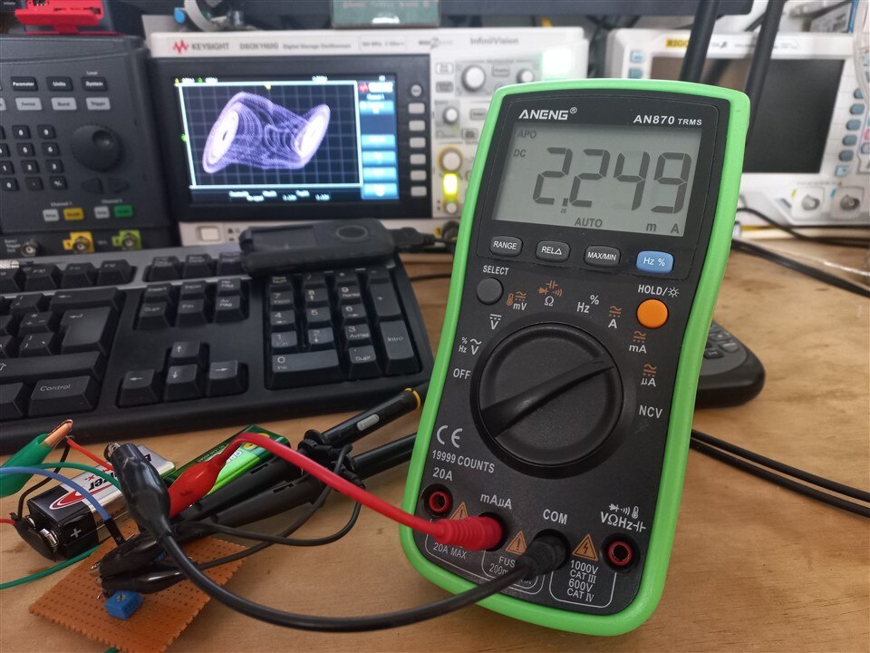
Making the Chua circuit and its power supply integrated, able to power it with a pair of 18650 rechargeable batteries, because using 9 volt batteries for a toy seemed too wasteful, and my 18650s have all come from recycled sources.
I also chose the transformer for that project through an overview of the kit played out as a reality dating show, which some found funny and entertaining, which was the goal!
I thought it would be fitting to have the kit overview at the end, since by then, we wouldn't be looking at the transformers thinking "they look like beds" as many of my friends mentioned after i sent them some pictures.
And the flybacks in the kit, other than the BA60951CS could be divided into three groups, based on their physical construction alone:
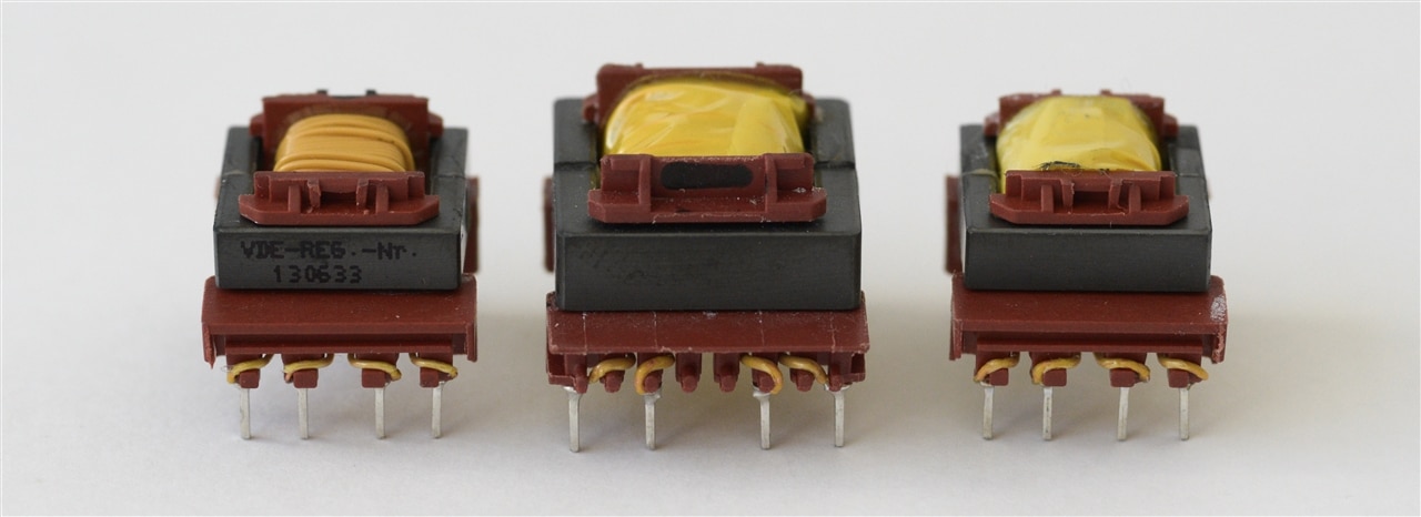
Ok! they kind of look like beds after all, but now we do know what they are!
Since blog 1 we explored the characterization of the transformers, and on this blog we breezed right through it, now understanding what the traces on the impedance analyzer meant, and why the specifications mattered.
Also, going through the kit as a part selection excersise, I think also helps newcomers who are wondering ( if they don't want to wind their own flyback) how to pick a transformer for their power supply.
It was also mentioned in this blog that the transformer was selected for its symmetrical secondary windings. This was meant to tie in with the final project, in which another great feature of flyback converters will be showcased!
So with the summary portion of the summary blog out of the way, let's look at the final project and how
It Flies Back!
As the previous blog ended with the selection of the transformer to use in this application, and the reasons for the selection were given, let's see the why of the why!
The circuit operates with a dual supply, with a positive and a negative rail. While for that circuit it would be easy to use a single supply and devise a virtual ground, it was also the perfect project to showcase an important but until now unmentioned feature of flyback converters:
As easy as it is to get one output out of the converter it is to get two, or more!
This is an idealized model of the converter I'll be building:
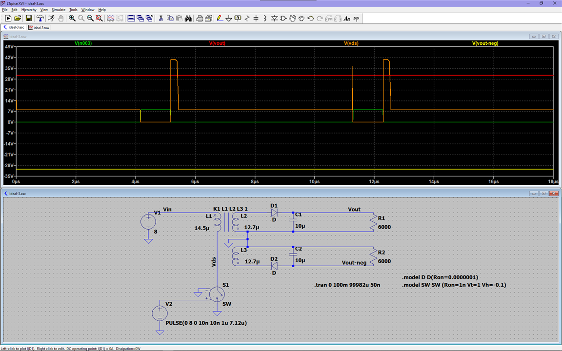
If we use the DCM formula we obtain results that don't match the simulation. So we're going a bit blind here:

But the simulation shows us a Vds of almost what is calculated with the DCM equation.
While I don't entirely understand how to design for multiple outputs, the simulations have proved they are good matches to reality, so using it I feel comfortable bringing the simulated circuit to life.
This will not be a thorough instructive but a demonstration of what can be achieved with flyback converters.
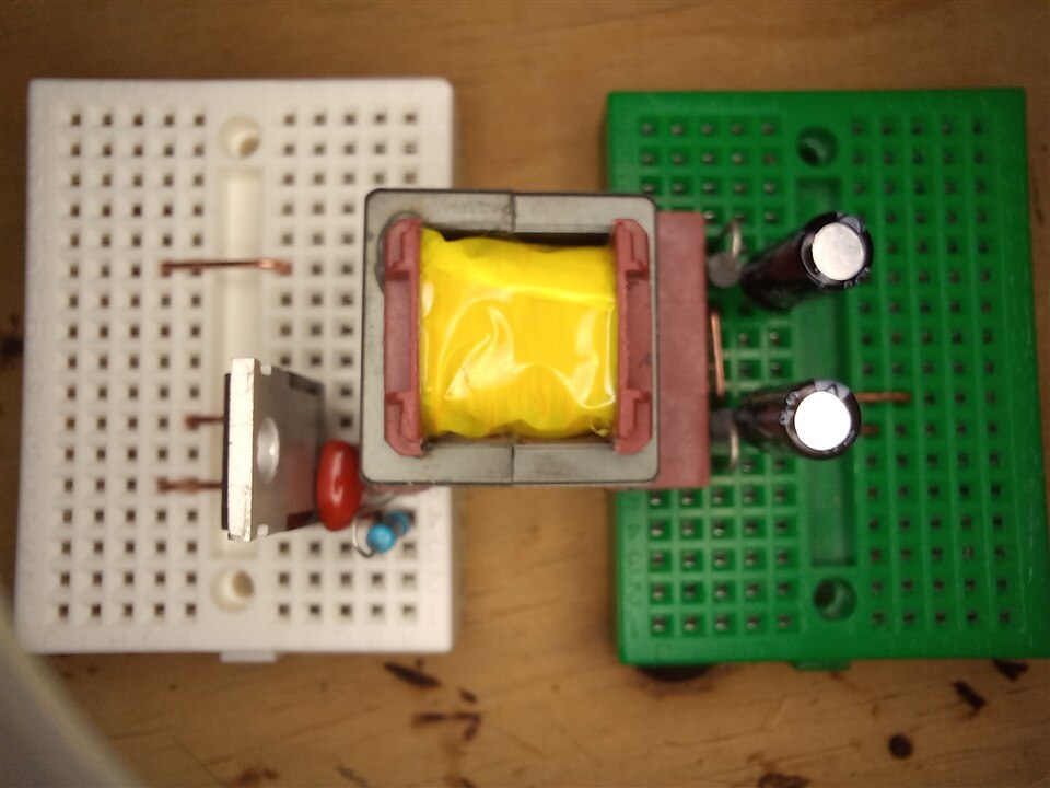
Here's the circuit on a breadboard, well, two, because of the staggered pins:
This time it needs to have a standalone controller, which in this case is just a simple PWM generator:
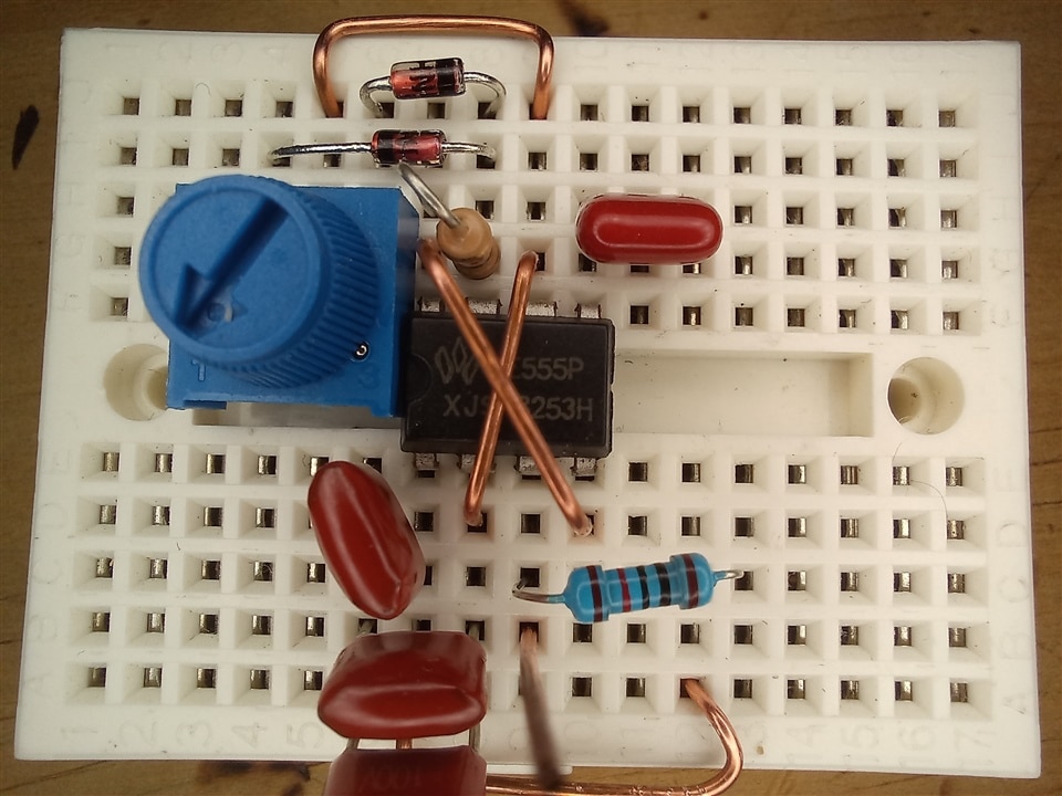
This generator is an astable 555. It works as a PWM generator maintaining a relatively constant frequency. The circuit was built according to this schematic found at electronicshub.org.
The three capacitors you see are a combination of two in parallel and that parallel in series with the other to get a capacitance that would get us close to the 132KHz the transformer operates at.
Here's the PWM circuit working. There's a limit for how low the duty cycle can be, but fortunately, this was enough to get the converter working within the 9-12V i was aiming for:
Next I went to rebuild the Chua circuit on a breadboard. I built everything on breadboards thinking this would help me figure out a reasonable layout to then move onto a PCB, but I was unable to do that in time, so the final result will also be presented on the breadboard:
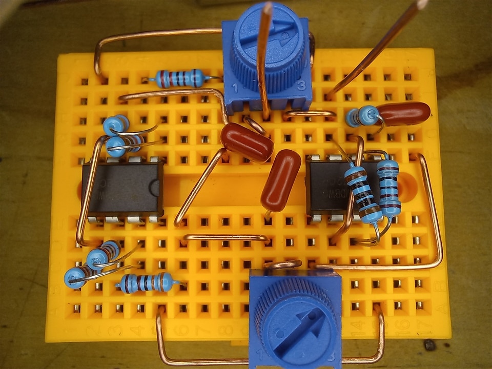
And a demonstration of it working with the +/- 9V supplied by two 9V batteries in series:
Great! now it's time to put it all together:
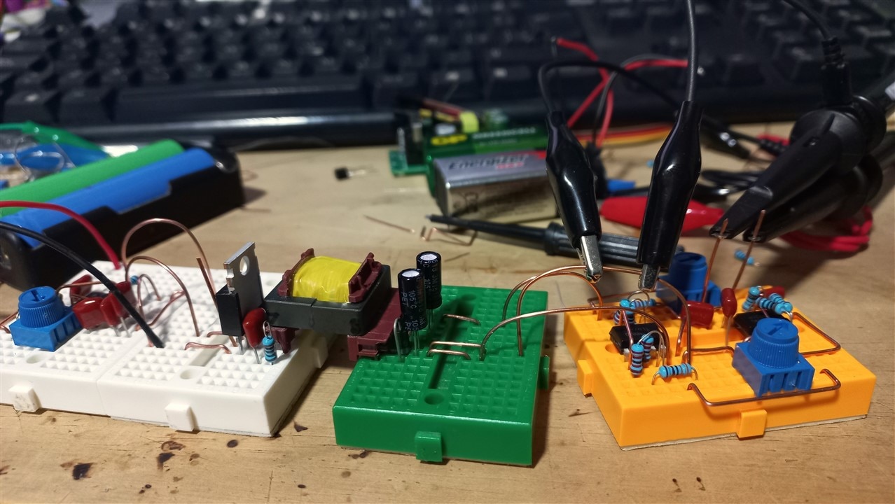
I intentionally connected each section to the next with big copper arches to have an easier time probing around.
With it all plugged in, it was time to test it:
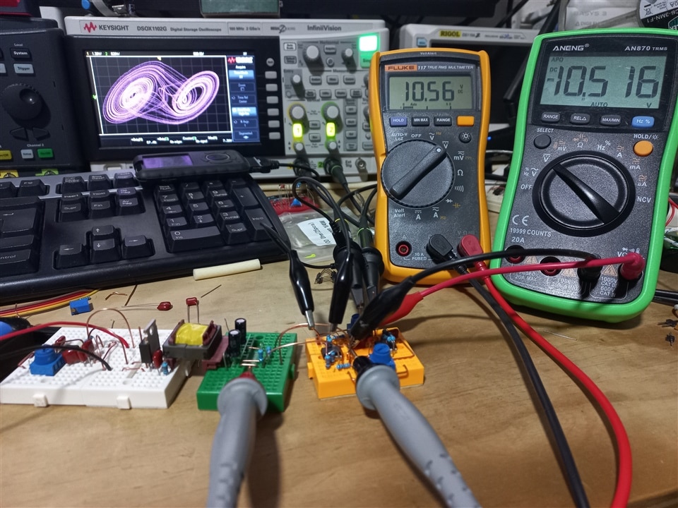
It worked wonderfully!
I now wanted to take a look at the supply by itself:
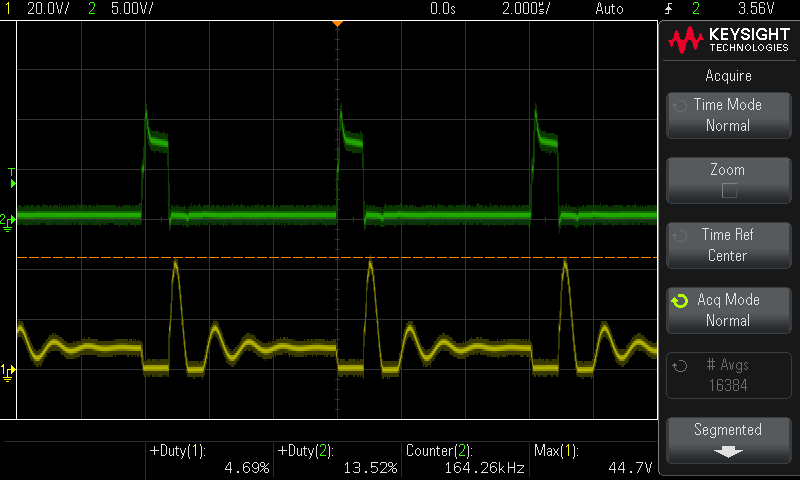
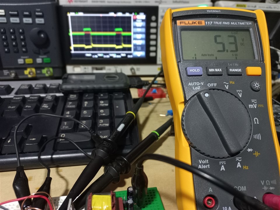
This is Vds in yellow, and Vgs in green, at the working dury cycle, but with no load.
With no load the output voltage between the positive and negative rails is wild!
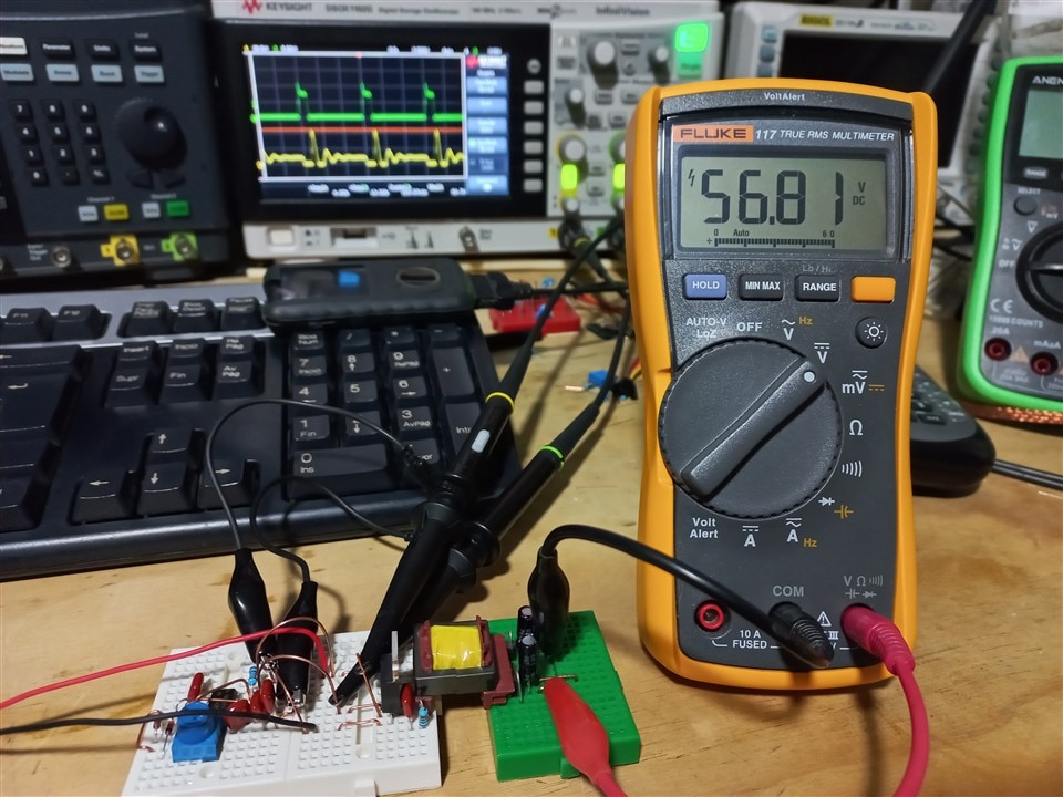
Now with the Lo-Z load:
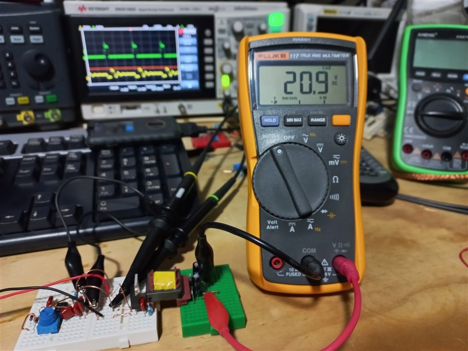
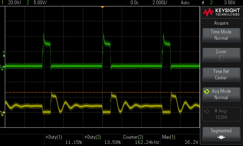
Vgs looks a lot more like what we've come to expect from a DCM flyback converter.
I don't understand why the difference is so big. But seeing that unloaded voltage at the lowest setting made me want to experiment further, so i set the duty cycle to the max:
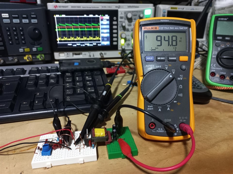
It reached almost 100V at the output! And the waveforms went crazy, but I couldn't capture that in time. Soon after, the MOSFET died:
And that was all that remained.
I found it really surprising that I was able to get almost 100V out of this converter, even if it lasted only a few seconds. But this just goes to show why flybacks are used by so many mad scientist aspirants on youtube. You can get them to work with very few components, and you can get them to do wild things that you might not even expect. I partially achieved my goal of integrating my chaotic attractor with a power supply and feel satisfied with what i learned while doing that.
To conclude, I must say thank you to Bourns and element14 for this challenge. I had tons of fun learning more about flyback converters, and was pleasantly surprised with the new things I learned. This was a very enriching experience, and the knowledge gained will certainly come in handy in the future!
While the prizes were a strong motivator to join the challenge, along the way my main motivation shifted and became providing entertaining educational content to the community.
I hope you learned something, and as always, all feedback is welcome.
Thank you!


-

BigG
-
Cancel
-
Vote Up
0
Vote Down
-
-
Sign in to reply
-
More
-
Cancel
Comment-

BigG
-
Cancel
-
Vote Up
0
Vote Down
-
-
Sign in to reply
-
More
-
Cancel
Children