


In my last posting, I delved into the issues revolving around rounding errors, thermistor tolerances and trying to fit a more accurate fifth-degree model to the data. While that was a very theoretical exploration, this post will be more concerned with the practical aspects of how one would make measurements with thermistors – for example, how is the resistance actually measured and what are some of the caveats or considerations involved. Once this is covered, then hopefully, I will be well on my way to actually running experiments with the components themselves.
Table of Contents
How Does My Equipment Measure Resistance?
We all know Ohm’s Law states that V = I x R for a resistor, but have you stopped to think, just how does my high-precision multimeter measure resistances? Is it sourcing a voltage, or is it sourcing a current? Or is it doing a bit of both?
In a stroke of empiricism, I decided to just hook up my Agilent U1241B to the terminals of a Keithley 2110 5.5-digit DMM in 2-wire resistance mode to see how it reacted.

With the 1MΩ impedance of the meter, the current passing through the resistance is pretty close to 1mA and the voltage across the impedance is about 1V.


Inserting different resistances in series (100Ω, 1kΩ, 10kΩ, 100kΩ, 1MΩ, 10MΩ), we can see that the current is not always consistent – the current depends on the range the DMM is in.

With the range set to a minimum resistance, the open-circuit voltage can reach 2.600V on this particular DMM.


Trying the reverse and using the Keithley 2110 to see what the Agilent U1241B is doing when its measuring resistance reveals that it has a completely different current and voltage which seemed to vary depending on the battery status in the meter.
Thankfully, a full explanation is available in some higher-end DMM datasheets. The Keithley 2110’s datasheet has the following table –

This indicates that it is testing using a test current, the magnitude depends on the range with five discrete values.

The Keysight EDU34450A 5.5-digit DMM has a fairly similar setup, however, there is one additional current step at 500µA.

The currents used by the handheld Agilent U1241B are completely different and not round-numbers either!

But sometimes even fairly expensive meters (e.g. Keysight U1461A) don’t actually have these details specified … so that’s a bit of a shame.
Knowledge of this is perhaps important because thermistors are vulnerable to self-heating errors. Measuring resistances involve passing a current through the thermistor which leads to resistive heating which affects the temperature of the thermistor depending on the medium it is in, whether it is flowing and the specific heat capacity of the thermistor itself. As the current passing through the thermistor changes depending on the range, auto-ranging behaviour of meters can result in step-changes in self-heating!

The calculated self-heating for the 10kΩ bead-type thermistor looks like this – notice the big discontinuity right around 30°C! Yikes! While the self-heating peak of about 2mW doesn’t seem like much, this may be detectable in still-air conditions.

Plotting the self-heating values in a log-scale provides a clearer indication of just how much the self-heating varies as a result of temperature and DMM range (the Keithley 2110 is assumed).
Some of the higher-end DMMs offer four-wire measurements, where two wires are used to inject current while the other two sense voltage. One thing to note is that the use of four-wire resistance measurements for thermistors is not as necessary as it may be with low-resistance RTDs, as the benefit is probably rather small given the (generally) higher resistances. That’s one potential benefit in reduced complexity, however, this doesn’t affect the self-heating issue whether two or four-wire measurements are used.
Interfacing with a Voltage Divider – It’s Not the Same, But It’s Convenient!
Now that I’ve managed to understand how a multimeter measures resistance, let’s now turn our attention to interfacing thermistors with an analog input. The most frequently recommended, and most basic circuit, simply is a voltage divider like so:

Sometimes this is drawn with the resistors swapped which will invert the output voltage characteristic, but basically it exploits the fact the thermistor resistance changing will change the output voltage in proportion.
It should be obvious that unlike the multimeter, this arrangement does not run the thermistor with a constant current. Instead, the input is a constant voltage, but the voltage on the thermistor itself depends on the ratio Rt/(Rt+R1)*Vcc. As a result, this means that the current flow is not constant and the power dissipated inside the thermistor has a curve characteristic.

The amount of power dissipated and the shape of the curve ultimately will depend on the choice of the other resistance in the voltage divider. However, it must be remembered that it is desirable to have as little power dissipated in the thermistor as possible, as any heat generated will cause self-heating errors which could be significant especially if the medium doesn’t remove heat quickly from the thermistor, or if the thermistor has a very low thermal mass. Another benefit of keeping the power dissipation low is simply a reduction in energy consumption, but of course, depending on the input impedance of your analog input, that can also introduce errors especially at high resistances. This is just one of the tradeoffs to bear in mind.
The Issue of Temperature Resolution and Divider Resistance
Given the highly non-linear resistance response of a thermistor, the issue of achievable temperature resolution is a problem as most ADCs have linearly-spaced steps. As a result, the resolution of temperature achieved will vary depending on the steepness of the resistance-versus-temperature curve at that temperature.
However, there is something we can do to push things towards our favour – one of these is adjusting the other resistance in the voltage divider so that we can change the shape of the resulting voltage-versus-temperature curve to give us the resolution we want within the temperature range of interest.
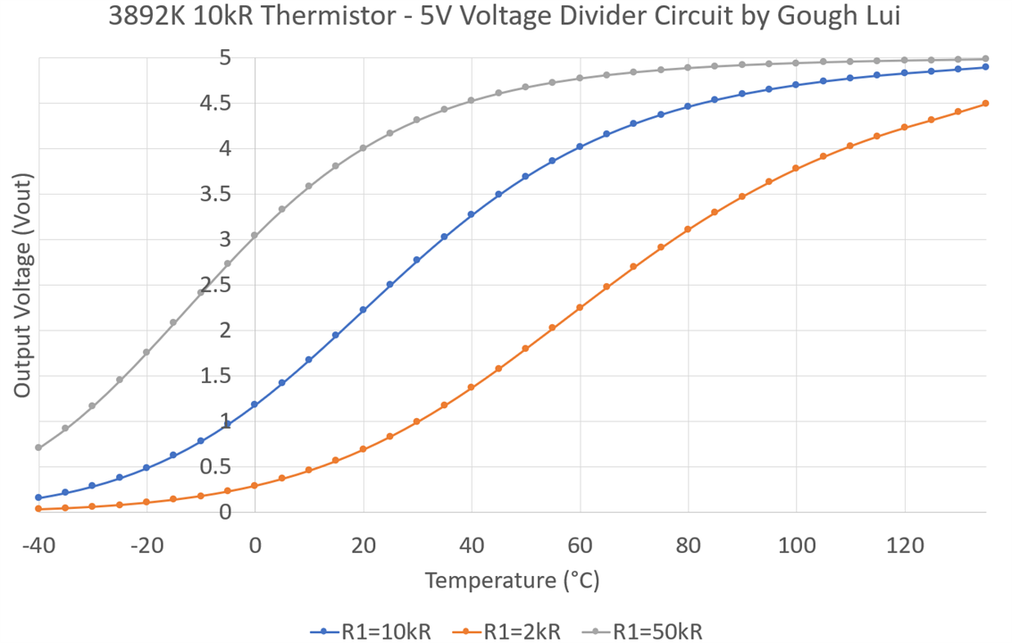
This example focuses on the 10kΩ bead thermistor and the effect of changing the other resistance in the voltage divider. In many cases, I’ve seen suggested circuits pick the other resistor equal to the thermistor’s nominal resistance to maximise resolution around 25°C (a sensible choice for “human” applications), but changing this resistance can have benefits too!
The voltage-versus-temperature curves are sigmoidal in shape – notice how reducing the resistance (in orange) throws away resolution at low temperatures to give us more resolution in the upper temperatures, while choosing a higher resistance (in grey) does the opposite.

For the most part, we are likely to capture these voltages with an analog-to-digital converter (ADC). Comparing the voltage step per 0.1°C across the temperatures and plotting the unipolar ADC step size (thick lines), we can see that with a 10-bit ADC, only a small range is able to achieve a 0.1°C temperature resolution. With a higher 12-bit resolution ADC, most (but not all) of the temperature range can be covered at 0.1°C resolution.
We can also turn this around and instead compute what the temperature step would be for each ADC bit for a given temperature.

Resistor choice is definitely important – especially if we are concerned with worst-case resolution. A step-based temperature resolution of over 20°C per step is seen for the 50kΩ resistor used with an 8-bit ADC near 120°C as the voltage curve is nearly flat at that point. Careful consideration of ADC step sizes and resistor value to maximise voltage gradient at the intended operating point is advisable.

Being more optimistic, this plot focuses on the best resolution achievable by a given combination. In this plot, we can see that with an 8-bit ADC, the best resolution for the three selected resistances range from 0.3 to 0.43°C per step, not a very precise measurement. At 10-bit, the resolution improves to 0.07 to 0.11°C per step.

Pushing for higher resolutions, a 12-bit ADC (in theory) would give us accuracies ranging from 0.019 to 0.028°C.

By 16-bit, we are now in the single-digit milli-degree Celsius territory, ranging from about 1.1 to 1.8m°C. This is where the fifth-order equations will really matter. The 24-bit result indicates it is sensitive enough that the resistor choice really becomes moot … however, such an implementation would be very difficult to achieve and would be extreme overkill for such non-precision thermistors.
High-resolution analog-to-digital converters (ADCs) are expensive, require some effort to implement (to ensure you actually get the resolution you paid for) and aren’t exactly easy to come by in this world of supply-chain issues. Thankfully, one can approximate the performance of a higher-resolution ADC (in an ideal case) simply through oversampling – for every one-bit of enhancement, you double the number of samples taken. The downside is that you are trading sample-rate for resolution and this only really “works” if the ADCs are very stable (which also mean stable references) without any systematic errors.
Taking one example – the 10-bit ADCs of classic ATMega328-based Arduino Unos will not give you a high-resolution result, however, if you want to approximate 16-bit accuracy, the six extra bits will cost you 64 samples which is not too onerous. Had you wished for 24-bit-equivalent accuracy, the 14 extra bits will cost you 16,384 samples which will mean that each reading will take more than one second (especially when using analogRead functions). This is excluding the additional time it would take for the microcontroller to compute the average and scale the result to your intended output range. However, at least this approach doesn’t cost any extra money and allows you to tune the resolution within a range.
“Linearisation” of a Thermistor … Is a Parallel Resistor the Cure?
While doing research about thermistors, I came across a variation of the above circuit where the thermistor had a parallel resistor across it. It was claimed to provide “linearisation” which seemed a bit curious to me, but since I have a worksheet, I decided to explore it as a mathematical exercise.

I picked a few values to parallel with the thermistor to compute the equivalent resistance at the given temperature. We’re already familiar of the very non-linear nature of the thermistor – the linearised lines have much lower resistance (due to the parallel resistance) but also look straighter.

However, zooming in shows that the “linearised” results still have a noticeable curve to them. The reduced resistance may make measurement more difficult as well.

But if all we’re interested in is a limited temperature range, the lines seem to be “roughly” straight over a range of 10 degrees either side of the temperature corresponding to the thermistor resistance value matching the paralleled resistance.
While it seems this “trick” works in an analog sense over a limited temperature range, for high precision or wider temperature ranges, it is better to use a high-resolution ADC and either a model equation or a lookup table approach. However, where analog circuits with proportional output are necessary, this could be a simple approach to improving the linearity of the thermistor enough for the intended application.
Other Circuit Considerations
Measurement accuracy isn’t just related to the ADC and oversampling used – the stability of the supply voltage is also important as that will affect the output voltage directly and potentially affect the ADC reference as well. Having a stable voltage would be ideal, however, the use of a Wheatstone Bridge circuit could help by allowing a sensitive differential measurement between an unknown divider and a known divider thus tuning out such errors. As it is differential, it may aid in measurement of smaller differences (such as may occur using the resistor linearisation method).
Similarly, the absolute accuracy of the other resistor in the divider chain will have an impact on the measurement error. Perhaps less considered is the temperature coefficient of this resistor – if it is subjected to significant temperature swings, the temperature coefficient will factor into measurement errors as well.
Finally, where high resistances are involved, humidity and contamination of the PCB (by airborne particles, flux, etc) could result in leakage currents that could falsely reduce the measured resistance as they form a phantom parallel resistor. Thus care may need to be taken especially for low-temperature measurements. Such an effect may exist as well due to the input impedance of the ADC which may not be negligible in case of higher-valued thermistors and resistances.
Conclusion
The way a digital multimeter measures resistance is to source a reference current and measure the developed voltage. While this sounds simple, the sourced current varies depending on the range, which means that the thermistor’s self-heating can significantly change as the meter changes ranges (e.g. during an auto-range operation). This characteristic of ‘stepped” self-heating is distinctly different from the smooth “hump” that is seen from a standard voltage divider input circuit. Such a circuit requires careful choice of the resistor to ensure maximum resolution around the temperature of interest, which may involve a trade-off of resolution at extreme temperatures. Better results can be obtained with higher-resolution ADCs or with oversampling, however, additional considerations such as the stability of the reference, supply voltage, accuracy of divider resistor and temperature coefficient are necessary. Current leakages due to contamination or input impedances can also contribute to errors.
It was interesting to see that the addition of a parallel resistor allowed for “linearisation” of the thermistor’s resistance which could be useful in simple analog proportional circuits operating at limited temperature ranges, however, using a high-resolution ADC and a model or look-up table still seems to be the more accurate approach. Higher accuracy may also be possible with the use of a Wheatstone Bridge style circuit which has a known-reference leg, allowing sensitive differential measurements to be made.
As usual, if you’d like to fiddle with some of the numbers I’ve graphed in this blog, the spreadsheet is available for download (although it’s not pretty) from here - Thermistor-Vdiv.zip
[[Characterising Thermistors Blog Index]]
- Blog #1: Characterising Thermistors - Introduction
- Blog #2: Characterising Thermistors - What's In The Box?
- Blog #3: Characterising Thermistors – A Quick Primer, Beta Value & Steinhart-Hart Coefficients
- Blog #4: Characterising Thermistors – An Inconvenient Truth, Taking Things to the Fifth Degree
- Blog #5: Characterising Thermistors – Measuring Resistance Is Not So Easy!
- Blog #6: Characterising Thermistors – Is Self-Heating a Problem or Not?
- Blog #7: Characterising Thermistors – Boiling, Freezing and Zapping the Truth Out of Them!
- Blog #8: Characterising Thermistors – Practically Running Multiple Thermistors
- Blog #9: Characterising Thermistors – Multi-T Results, Insulation R Redux, 5th Order Fits & Model Performance
- Blog #10: Characterising Thermistors – Multiple Thermistors on ESP8266
- Blog #11: Characterising Thermistors – Show Me Your Curves
- Blog #12: Characterising Thermistors – Sticking Rings on Tabs & Sinks, Absolutely Crushing It!
- Blog #13: Characterising Thermistors – Pulling Out, Overload, Response Time, Building a Flow Meter & Final Conclusion
Top Comments