


By now, you’re probably bored of all the theoretical experiments and minor side-quests that have been covered in the six blogs to date. At last, we come to a blog about the thing this whole project was pitched at doing which is characterising thermistors. This time around, I’ll be measuring the resistance of the thermistors at relatively well-known temperatures, computing beta values and testing its insulation resistance.
Table of Contents
Wonderous Water!
For all of the experiments in this section, I will be performing them under water immersion. The natural question is to ask why?
As it turns out, water is a very wonderous liquid. For one, it has a high specific heat which means it takes a lot of energy to raise or lower its temperature. This means that it keeps its temperature better than other fluids, which helps as it stabilises measurements and also reduces the influence of self-heating.
Another important property is its boiling and freezing point temperatures, at very approximately 100°C and 0°C respectively, dependent on the purity and atmospheric pressure. These temperatures are well known precisely because of the phase-change properties of water.
When you boil water, what happens when the water reaches 100°C? Does it all flash into steam? No! Instead, the water reaches a “rolling” boil. The reason for this is because of the latent heat of vaporisation – in other words, it takes a lot of energy to move from a liquid to a gas phase, thus the boiling water will sit at around 100°C until the water has evaporated entirely at which point the temperature can rise further. This effect is cleverly used in rice cookers to detect the end of cooking and to engage the keep-warm mode.
Similarly, it also takes a lot of energy to change from solid ice to liquid, the latent heat of fusion. As a result, ice and water can coexist in a mixture which will happily stay at around 0°C until all the ice melts away, even though the ice itself may be colder than this. Such an ice-bath is pretty common in laboratories that perform temperature-sensitive work.
These phase change points result in a relatively stable temperature reference that is more accurate than many measurement devices (e.g. thermocouple probes) and is commonly used for calibration due to the ease of implementation.
Experiment: Insulation Resistance Testing
While the thermistors are epoxy-coated and have insulated leads, and the datasheet indicates a dielectric strength of minimum 1500VAC for three seconds, and a minimum of 100MΩ at 500VDC in metallic balls, I wanted to test the insulation resistance just in case they have been damaged. If they fail the test, then it’s probably not a good idea to dunk them into water! Such damage can happen in case the leads have been yanked and the epoxy coating has cracked.
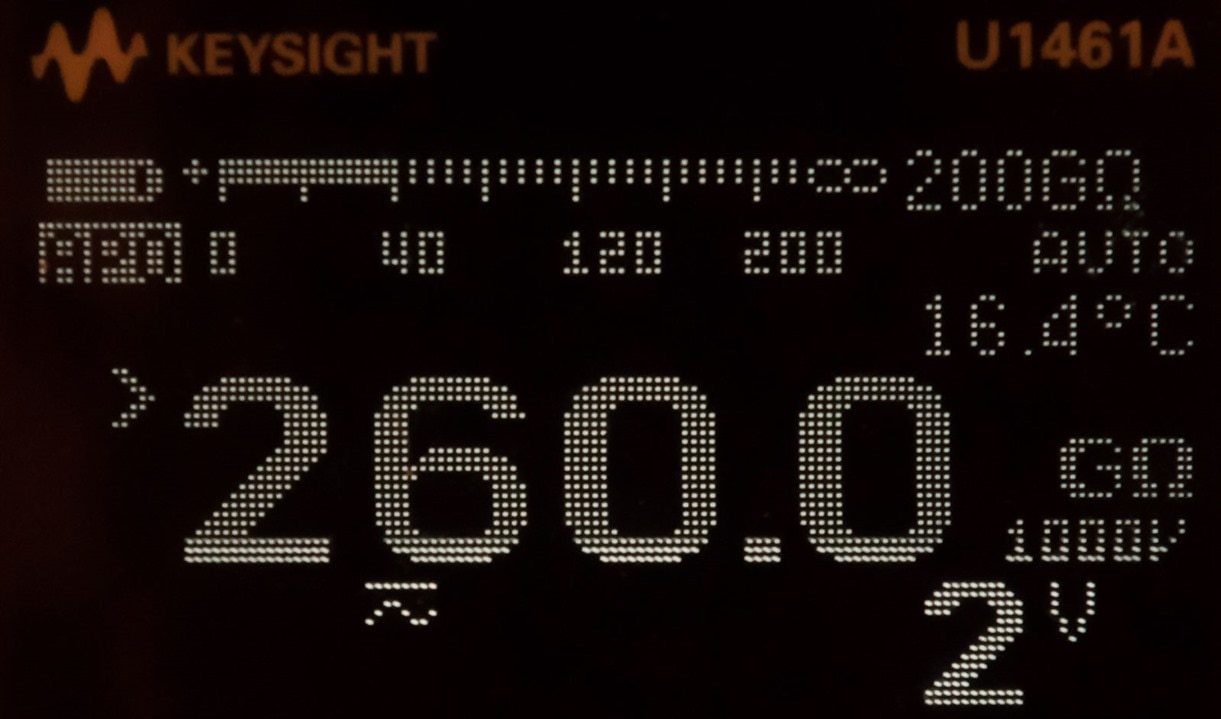
I can report all of the beaded thermistors measured off-scale on the Keysight U1461A Insulation Resistance Test DMM when immersed in a stainless thermos of water, with one leg of the test connected to the thermos itself. This indicates an excellent result, as the water barely measures in the 40kΩ range.
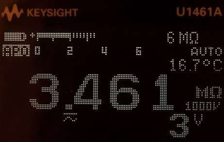
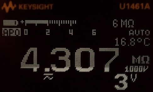

Testing the ring thermistors gave mixed results, but I’m not sure as to the cause. Perhaps it’s the metal ring touching the metal thermos giving more leakage, the greater-than-expected test voltage of 1000V or actual leakage through coupling into the test leads themselves (as the thermos forms a pretty big electrode which may form an axial capacitor with the centre lead). Regardless, the results are still high enough to indicate no direct connection with the water, which is fine for my needs.
Experiment: Measurements at Boiling Point
To measure at boiling point, I needed to get some water and boil it. The easiest way, being in a 230V country, is to use an electric kettle but those have automatic “pesky” shut-off switches which may get in the way.
Fortunately, I had a broken soymilk maker machine that I had salvaged the bottom from and rewired such that its 1.1kW element was directly connected to the IEC socket for relatively gentle non-stop boiling action.
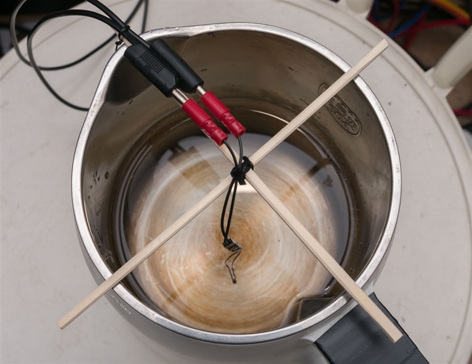
Using a pair of disposable takeaway chopsticks, some twisty-ties and by misusing bullet crimp sockets as 4mm banana sockets, I had myself an apparatus by which the thermistor can be suspended about half-way up the water column as it boils, thus not over-reading temperature from the hotplate itself, and not under-reading temperature from the top surface where heat is convecting away.
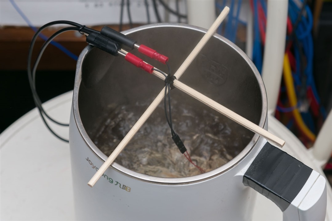
Believe me – this thing does get to a rather vigorous boil … but thankfully, as it is a soymilk maker, there is ample room above to catch the splashes. There is 1.5L of water in the pot, if you can believe it.
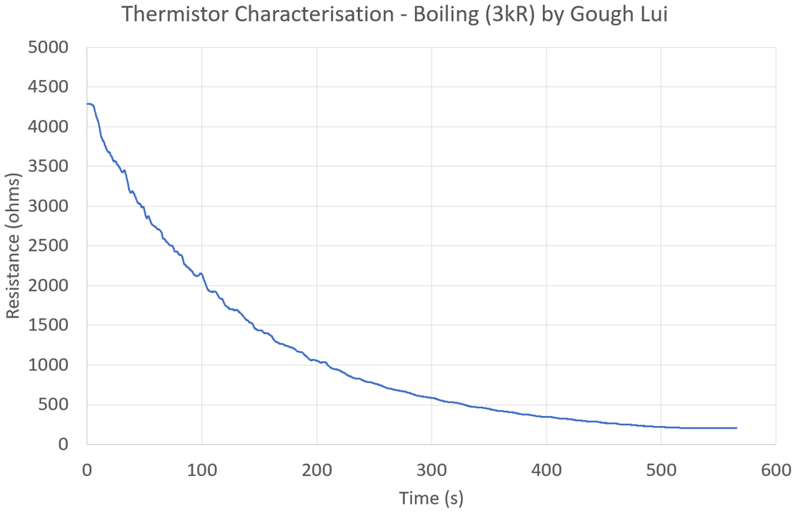
The thermistor was measured using the Keithley 2110 5.5-digit DMM, noting that self-heating is a non-issue for this experiment. Starting a new boiling experiment with water at room temperature, we get a very nice curve forming with a few bumps due to the convection currents in the water.

As the water reaches a boil, using a more zoomed-in scale, we can see the resistance plateaus somewhat. It isn’t entirely perfectly stable – this is likely because of the occasional steam bubble and jostling in the water, so I took the average of the readings in the plateau area to determine the actual resistance.
For completeness, I also measured the atmospheric pressure using an Si7021 sensor – at the time, it was 1003.13hPa which would have corresponded to 99.71°C boiling point. This is close enough to 100°C compared to other sources of error that this fact was deemed negligible.
Experiment: Measurements at Freezing Point
To test for freezing point, I needed to make an ice-bath. Unfortunately, I don’t have an ice shaver which would have been perfect for this – in fact, I didn’t even have ice cubes (as we don’t drink our drinks with ice) …

… so I had to make some! This took longer than expected for our ailing freezer, which necessitated delaying my experiment for a day.

For this part of the experiment, the chopsticks make a reappearance, but this time just one was needed. The thermistor was twisty-tied to the chopstick at around 2cm from the bottom.

This is so that when it is inserted in the silvered, double-walled vacuum carafe (which helps to maintain the temperature) in the slit made in the Perspex cover, the probe will sit away from the top (where the ice is floating) and the bottom to give a more representative temperature.
To make this work, I decided to agitate the mixture between each tested thermistor, but once the thermistor is put in, I let it rest for a long time (usually at least 15 minutes) to try and reach an equilibrium.

My first attempt failed hilariously as I thought cold tap water and ice were good enough with a vacuum carafe. Instead, the 16°C water melted the ice in quick order, disturbing the ice-to-water ratio and threatening to end my experiment as soon as it started. I had to recreate a new batch of ice and use refrigerated water to minimise the temperature delta to preserve the ice long enough to test all ten thermistors (taking the better part of the day).

Similarly, there was a curve, but it is much more rapid at first as the thermistor reacts to the temperature change, and then seems to increase much more slowly. Some thermistors don’t seem to exactly stop …

… but I wasn’t going to wait around for too long otherwise all my ice would be gone! This could have been a sign that the thermistor may have been slightly affected by nearby ice colder than 0°C, but given the specific heat of water and the height of mounting the thermistor, I found that unlikely. Instead, as the result deviated less than 1Ω in 3 minutes, I was willing to call it there using the highest value as the result.

There were, however, some thermistors which did plateau out very nicely … with some reading noise as is customary with real-life measurements. Occasionally, mains power borne noise would also be seen in the raw data. In these cases, the plateau section was averaged to find the true resistance value.
Results – In Spec or Not? What is the Beta Value?
The results of all of the experiments are summarised below:

In the case of the boiling-point results, all thermistors except the 10kΩ bead type and the final 10kΩ ring type thermistors measured in-tolerance. The errors generally were positive (higher resistance than the nominal) in direction, indicating lower temperature being sensed, but this may be down to the fact the pressure would have led to the temperature reaching 99.71°C (-0.29%) and the way the geometry of the pot and thermistor height in the water column. But it is nice to see good agreement across the board.
The issue with the 10kΩ bead type under boiling was repeatable – I initially thought it was a measurement error (e.g. it may have touched the heating element at the bottom) so I took a second measurement. The two measurements agreed within 2Ω indicating this deviation is real. The reason behind it was not determined – perhaps it was damaged in shipping or when I fitted the connector to it?
In the case of the freezing-point results, it was good to see virtually all of the thermistors were in specification, with a spread of positive and negative errors, many small. The only exception was, again, the final 10kΩ ring type thermistor.
Calculating the Beta value for 0-100°C yielded results which were around 3900-3985K for the bead type thermistors, and are 3755-3756K for one type and 3478K for the other. These values deviated a small amount from the stated nominal Beta values as those are determined for a different temperature range (0-50°C for beads / 25-85°C for ring type), so while the stated Beta tolerance is 1%, I consider results within 2% to be fine (in green), with the ones slightly above 2% (in yellow) being close. The outlier is, again, the final 10kΩ ring thermistor!
What the Ring Thermistor is This?!
Judging from the results, you’d be forgiven if you thought I had tested the 3800K version (laser marked 10MB) twice – the results seem to match. But because of the way I handle the thermistors, it was not possible that I had mistaken them – they move from one tray to another, so double-testing was not possible.
In fact, I was so confused, I tested all three ring-type thermistors a second time, coming to the same answer … I seem to have two 3800K thermistors and one 3500K thermistor. Was this a sorting error?


Cracking out the macro lens reveals that I have just one marked 10MB (3800K) and two marked 10MA (3500K) as per the list of parts we should have received. This only makes the result even more mysterious – is this an issue with quality control? Regardless of the cause, I’d have to say that the laser markings on the rings are awfully hard to read given the textured finish on the ring terminals. Perhaps they should be etched thicker or marked in a different way (perhaps stamped into a flat-part)?
Conclusion
This blog details my relatively successful efforts to characterise the thermistors at two points – the boiling point and freezing point of water. To do this, I first established the integrity of the thermistors through testing their insulation resistance before using makeshift apparatus to perform the tests. The data was able to indicate most thermistors were easily within-range of their specification, with a key exception being the boiling-point resistance of a 10kΩ bead thermistor and a 3500K 10kΩ ring thermistor that behaved in-spec for a 3800K 10kΩ ring thermistor instead. This finding was surprising, suggesting some quality control hiccup may have occurred, although it was also found that the laser markings on these ring-thermistor parts is difficult to read.
Of course, there is still plenty of time for this design challenge, so in future parts, I’ll be working on some other characterisations, putting them into active service and perhaps prototyping something with them. But I’m glad to have already done this part – covering a good chunk of what I had initially set out to do.
The raw data and plots from all of these available for download - Thrm-Boil-Freeze.zip
[[Characterising Thermistors Blog Index]]
- Blog #1: Characterising Thermistors - Introduction
- Blog #2: Characterising Thermistors - What's In The Box?
- Blog #3: Characterising Thermistors – A Quick Primer, Beta Value & Steinhart-Hart Coefficients
- Blog #4: Characterising Thermistors – An Inconvenient Truth, Taking Things to the Fifth Degree
- Blog #5: Characterising Thermistors – Measuring Resistance Is Not So Easy!
- Blog #6: Characterising Thermistors – Is Self-Heating a Problem or Not?
- Blog #7: Characterising Thermistors – Boiling, Freezing and Zapping the Truth Out of Them!
- Blog #8: Characterising Thermistors – Practically Running Multiple Thermistors
- Blog #9: Characterising Thermistors – Multi-T Results, Insulation R Redux, 5th Order Fits & Model Performance
- Blog #10: Characterising Thermistors – Multiple Thermistors on ESP8266
- Blog #11: Characterising Thermistors – Show Me Your Curves
- Blog #12: Characterising Thermistors – Sticking Rings on Tabs & Sinks, Absolutely Crushing It!
- Blog #13: Characterising Thermistors – Pulling Out, Overload, Response Time, Building a Flow Meter & Final Conclusion
Top Comments