


Previous posts for this project:
- [CaTS] ForgetMeNot - Index
- [CaTS] ForgetMeNot - Week 0: Project Description
- [CaTS] ForgetMeNot - Week 1: EnOceanPi and Sensors
- [CaTS] ForgetMeNot - Week 2: Elro CoCo and Pi Cam with OpenHAB
- [CaTS] ForgetMeNot - Week 3: Data persistence and charts with OpenHAB
- [CaTS] ForgetMeNot - Week 4: Arduino-OpenHAB communication
- [CaTS] ForgetMeNot - Week 5: Getting familiar with EAGLE
- [CaTS] ForgetMeNot - Week 6: Getting to know the TBS1052B-EDU oscilloscope
- [CaTS] ForgetMeNot - 3D Printing: EnOcean sensor bracket
- [CaTS] ForgetMeNot - 3D Printing: EnOcean rocker switch and magnet holder
- [CaTS] ForgetMeNot - 3D Printing: Food dispenser prototype
- [CaTS] ForgetMeNot - 3D Printing: Weighing scale
- [CaTS] ForgetMeNot - Security: Some basic tips
- [CaTS] ForgetMeNot - Minion: Dave, the gassy minion
Introduction
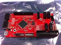
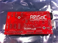
Some weeks back, it was announced that the challengers in the Forget Me Not challenge would get to use highly exclusive prototype versions of the RPiSoC.
The RPiSoC is an opensource expansion board for the Raspberry Pi (which can also work standalone) currently seeking funding on Kickstarter.
I received my prototype board last week, and gave it a spin this weekend. These are my initial findings ...
Resources
On my mission to get to know the RPiSoC a little better, I came across some useful resources. Here's a listing:
- RPiSoC Kickstarter page with info on the board, updates, etc ...: https://www.kickstarter.com/projects/embeditelectronics/rpisoc-a-development-board-with-raspberry-pi-compa
- element14 Webinar: RPiSoC: A Development Board with Raspberry Pi Compatibility
- RPiSoC GitHub repository with code, schematics, bootloarder, etc ...: https://github.com/EmbeditElectronics
- Documentation on the RPiSoC Python API: Welcome to the RPiSoC Python API documentation! — RPiSoC Python API 1.1.0 documentation
- Video tutorial on the RPiSoC Python API using Raspberry Pi: https://www.youtube.com/watch?v=clJlj0c77nA
By backing the project on Kickstarter (even if only 1USD), it becomes possible to post comments on the project page. The guys a Embedit have been very responsive.
Connecting the board
The board was delivered to us, as is. No cables. So first thing on the agenda was to figure out how I would connect the RPiSoC to my Raspberry Pi.
GPIO
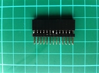
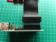
I still had a GPIO cable from a Pi Cobbler and decided to use that in order to connect the RPiSoC to the Pi. It would have been fine in case of a regular Raspberry Pi Model B. However, with the extended GPIO on the B+, the GPIO cable no longer fits. Searching through my parts, I found some components to make a kind of spacer, which would allow me to use the GPIO cable. Not fancy, but functional.
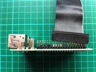
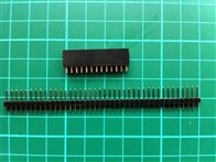
After some fiddling and soldering, I was able to connect the B+ to the RPiSoC.

 CAUTION
I assumed (and everyone knows that assumption is the mother of all screw ups) pin 1 on the RPiSoC GPIO header would connect to pin 1 on the RPi GPIO header. But just to be sure, I decided to check and double-chek how to connect the GPIO cable (I wouldn't want to have fried my RPiSoC prototype after a single day ...).
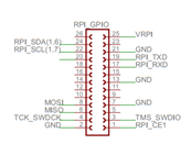
It seems pin 1 of the RPiSoC GPIO header doesn't map to pin 1 of the RPi GPIO header, but rather to pin 26. This means everything is reversed!
It would have made more sense to have a one-to-one mapping (pin 1 to pin 1, pin 26 to pin 26) of the pins on the GPIO header, to avoid confusion and mistakes.
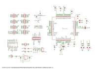
Looking at the schematic found the in the GitHub repository, the reversing of the pins is confirmed:
Pfiew, I probably almost fried my RPiSoC by assuming pin 1 of both GPIO headers should be connected together ... That would've been bad ...
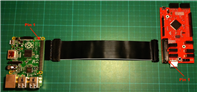
As requested in the comments, here's a picture of how it should be connected:
 UPDATE
I posted the question on Kickstarter and got a reply on this topic. Here it is:
Creator Embedit Electronics
Hi Fredrick-
Good catch, we will clarify the GPIO mapping in our documentation. The reason it is like that is for the easy connection of a ribbon cable. The original revision was the way you suggest, and it made it such that the ribbon cable would have to be drawn over one of the boards to connect them properly. With the pin out reversed, the ribbon cable connects between the two boards so your access to each of them are not obstructed by the ribbon cable. Good point though!
Creator Embedit Electronics
Oops- it appears I only half answered your question upon re-reading it. You actually bring up an excellent point which will be true for all the Forget Me Not users:
While the pinout was corrected to reflect the orientation needed for use of a ribbon cable, the silkscreen and pin names were not changed! This means Fredrick is spot on for the prototype runs- Pin X on the RPi is equivalent to pin 27-X on the RPiSoC (in terms of the naming scheme for the silkscreen).
This is fixed for the version being professionally manufactured, but it was an oversight that slipped past us on that revision.
So good eye Fredrick! We will definitely add that to the documentation for other Forget Me Not users.
Power
The RPiSoC can be powered in different ways:
- microUSB connection
- miniProg
- RPi GPIO
For my initial testing, I'll be powering it from the Raspberry Pi GPIO. To do this, I needed to ensure the power jumper was set correctly.
To power via the Pi's GPIO, the two pins furthest away from the microUSB port need to be connected.
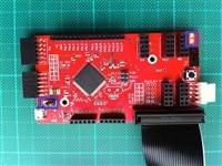
Once the Pi is powered on, so should the RPiSoC. The red power LED in the upper right section of the RPiSoC should light up.
Using SPI or I2C
The RPiSoC can be configured to communicate with the Pi via SPI or I2C. Setting up and using either SPI or I2C is already extensively covered in the RPiSoC documentation, so I won't duplicate it here.
And finally, Changing communication protocol used by the API.
By default the RPiSoC is configured to use SPI, and this is what I'll use.
Python API
There is a Python API available to interface with the RPiSoC from the Raspberry Pi. Instructions on how to download the scripts are provided here.
After following the instructions, you will end up with following structure:
pi@webserver ~ $ ls -l psoc_2_pi/
total 12
drwxr-xr-x 3 pi pi 4096 Sep 14 13:11 API_Python_v_1_1_1
drwxr-xr-x 6 pi pi 4096 Sep 14 13:12 PSoC Creator
-rw-r--r-- 1 pi pi  820 Sep 14 13:12 Readme.txt
Containing a bunch of Python scripts:
pi@webserver ~/psoc_2_pi/API_Python_v_1_1_1 $ ls -l
total 196
-rw-r--r-- 1 pi pi  1101 Sep 14 13:11 DELSIG_ADC_voltmeter.py
-rw-r--r-- 1 pi pi  2523 Sep 14 13:11 PWM_demo.py
-rw-r--r-- 1 pi pi  1654 Sep 14 13:11 PWM_demo.pyc
-rw-r--r-- 1 pi pi   487 Sep 14 13:11 README.txt
-rw-r--r-- 1 pi pi  1469 Sep 14 13:11 SAR_ADC_voltmeter.py
-rw-r--r-- 1 pi pi  1616 Sep 14 13:11 SAR_ADC_voltmeter.pyc
-rw-r--r-- 1 pi pi 26870 Sep 14 13:11 analog.py
-rw-r--r-- 1 pi pi 28806 Sep 14 13:11 analog.pyc
-rw-r--r-- 1 pi pi 25400 Sep 14 13:11 digital.py
-rw-r--r-- 1 pi pi 24339 Sep 14 13:11 digital.pyc
-rw-r--r-- 1 pi pi  1304 Sep 14 13:11 function_generator.py
-rw-r--r-- 1 pi pi  1340 Sep 14 13:11 function_generator.pyc
-rw-r--r-- 1 pi pi  1614 Sep 14 13:11 pin_demo.py
-rw-r--r-- 1 pi pi   985 Sep 14 13:11 pin_demo.pyc
-rw-r--r-- 1 pi pi 14522 Sep 14 13:11 rpisoc.py
-rw-r--r-- 1 pi pi 13710 Sep 14 13:11 rpisoc.pyc
-rw-r--r-- 1 pi pi  1434 Sep 14 13:11 servo_test.py
-rw-r--r-- 1 pi pi   159 Sep 14 13:11 test_del.py
drwxr-xr-x 2 pi pi  4096 Sep 14 13:11 untested
Testing
With everything connected and set up, it was time to make something blink! Nothing too fancy at first, but gradually build understanding of how to interface with the RPiSoC using the Python API.
Blink
First, I went to the Python script folder, and started Python:
pi@webserver ~ $ cd psoc_2_pi/API_Python_v_1_1_1/
pi@webserver ~/psoc_2_pi/API_Python_v_1_1_1 $ sudo python
Python 2.7.3 (default, Mar 18 2014, 05:13:23)
[GCC 4.6.3] on linux2
Type "help", "copyright", "credits" or "license" for more information.
>>>
Then, I imported all related to RPiSoC and specified to connect via SPI:
>>> from rpisoc import *
>>> RPiSoC('SPI')
I picked a random I/O port (Port 6, Pin 7) to connect my LED to, in order to test the DigitalOutput function:
>>> led = DigitalOutput(6,7)
Traceback (most recent call last):
  File "<stdin>", line 1, in <module>
  File "digital.py", line 107, in __init__
    raise ValueError('Invalid port number: Only Ports 4 and 5 available for output. ')
ValueError: Invalid port number: Only Ports 4 and 5 available for output.
For some reason that failed, even though the documentation indicates this pin as a general purpose I/O.
Watching the video tutorial, I saw Port 12 was being used (even if the current error message talks about only Port 4 & 5 being able to work as outputs).
So I decided to try again, this time with Port 12, Pin 7.
>>> led = DigitalOutput (12,7)
>>> led.Write(1)
>>> led.Write(0)
It worked, my LED was turning on and off! Not sure why it would work with Port 12 and not Port 6. I'll be asking the Embedit guys, in order to figure out what's up.
Anyway, this functionality will be useful in my project to trigger the control switch on a DC step-up boost converter connected to a 12V solenoid valve.
Using a single digital I/O, I'll be able to trigger the water dispensing mechanism (which I still have to assemble and test, more on that later).
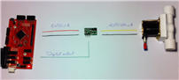
A Python script toggling the digital output can easily be called from openHAB using the exec binding, as I've done earlier, here.
Servo
The second thing I tried, was to control a servo using the RPiSoC and its Python API.
Create a servo object with following properties and start it:
- connected to Port 3, Pin 0
- pulse range from 900us to 2100us
- operating angle from 0° to 120°
>>> My_servo = Servo(0, 0.9, 2.1, 0, 120)
WARNING: Attempted to set PWM clock frequency greater than 2.526 MHz; this frequency cannot be gauranteed within a tolerance of 5%. Get the actual frequency with the GetClocks() method
>>> My_servo.Start()
Set the angle of the servo:
>>> My_servo.SetAngle(0)
>>> My_servo.SetAngle(90)
>>> My_servo.SetAngle(120)
>>> My_servo.SetAngle(0)
The feature will be used for the food dispenser part of the project, which I demonstrated in an earlier post using an Arduino.
Again, this can easily be triggered from openHAB using the exec binding to call a Python script.
Conclusion
I've only scratched the surface of what RPiSoC can do, but I wanted to get this post out before the end of the Kickstarter, hoping it would create additional visibility on the project.
There is approximately one week to go, and it is almost sixty percent funded. There are still some early adopter perks available, so go get one before it's too late!
The RPiSoC will simplify my project in the sense that everything that was originally offloaded to an Arduino, can now by offloaded to the RPiSoC and accessed via the Python API.
No more fiddling with I2C/SPI/Serial parsing of data etc ... the Python API makes it so much easier!
Because the RPiSoC uses SPI (or I2C) to communicate with the Raspberry Pi, it should be possible to connect it simultaneously with the EnOceanPi and my I2C RF433 transmitter.
I'll hopefully be able to try this out in the days to come, along with some other things such as my weighing and temperature sensors.
Stay tuned for more!
Top Comments