Omega provides several software tools to configure and manage Layer N devices. I will go through the available options and configure the components I need for my project
SYNC is an easy-to-use tool that can be used to configure Smart Probes and Smart Sensors.
SYNC tool can be launched by double-clicking the Omega.DeviceManager.exe file in the folder you selected during the SYNC setup procedure. A minor issue is that link to SYNC tool does not appear in the Windows' Start menu
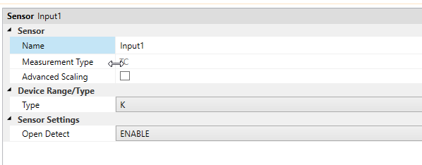
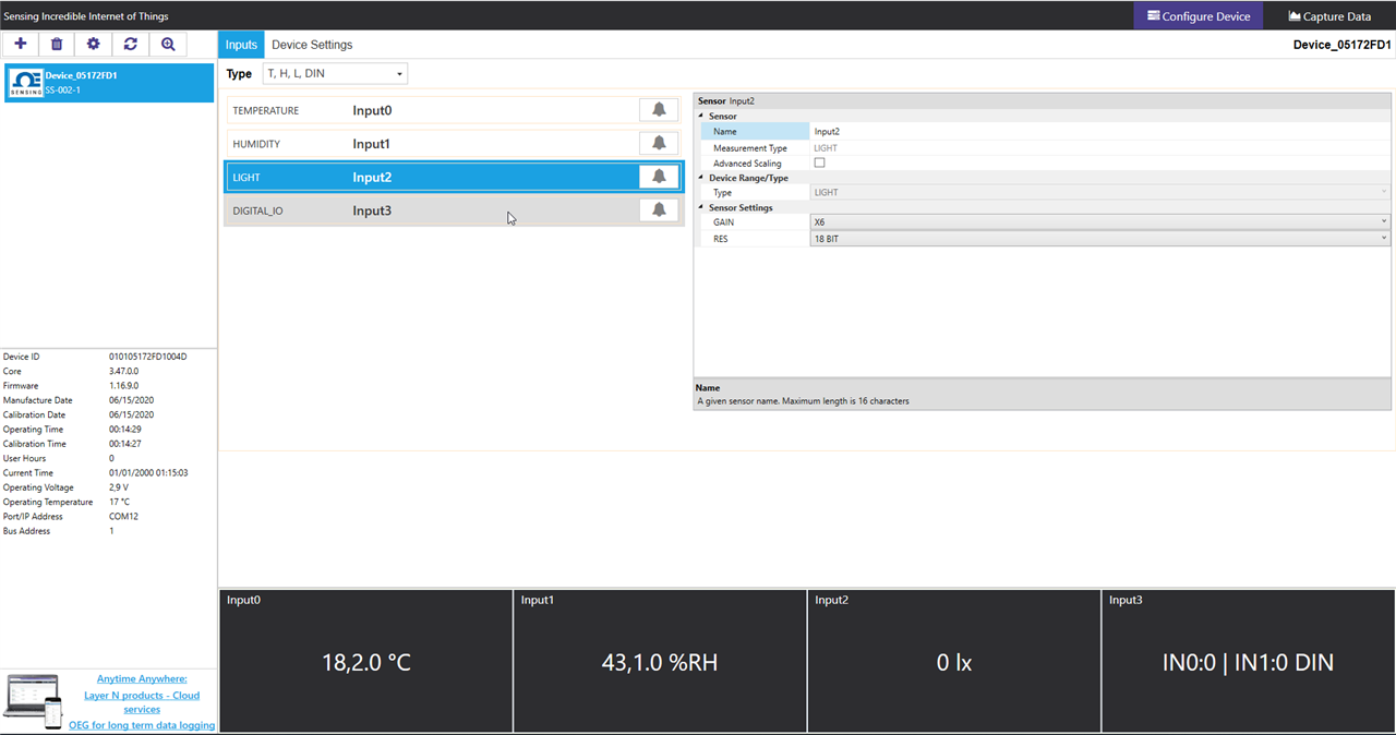
Let's see how the SP-005 Smart Probe and the SS-002 Smart Sensor can be configured.
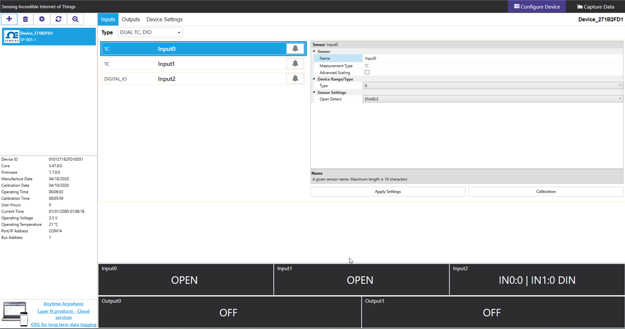
- Single TC
- Dual TC
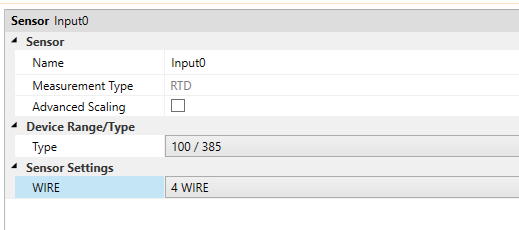
- RTD
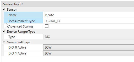
- Single TC, DIO
- Dual TC, DIO
- RTD, DIO
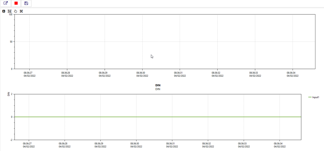
The second section is "Capture Data", which shows live data from the Smart Probe
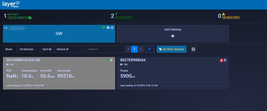
- Integrated with Enterprise Applications. OMEGA Enterprise Gateway can feed sensing data to the OPC UA compliant applications such as SCADA, HMI, MES etc. via OPC US server (licensed). Once the user adds OMEGA devices to the Gateway, the Gateway automatically exposes all sensing data as OPC UA nodes. The Enterprise application can then pull all OPC UA node values and display them on the screen.
- Standalone Solution for Sensing, Archiving, and Analytics. In many environment sensing applications such as hotel room temperature monitoring a building temperature/humidity monitoring, OMEGA Enterprise Gateway can provide real-time monitoring, alarms, notifications, archiving, and analytics that are required in these applications.
- it allows user to create custom dashboards. This could be an effective way to show data in an organized manner
- it allows user to define a Modbus device and a customized set of Modbus registers to read. This would probably simplify the implementation of the protocol converter, because I will not have to replicvate the behaviour of one of the Omega devices
- once the pairing button on the Smart Sensor displays a solid orange LED light in the center of the pairing button, Smart Sensor is ready to be connected to a Layer N Gateway
- push the pairing button once and the LED will begin to flash green
- quickly push the pairing button on the Gateway once and its LED will also flash green
- when the Smart Sensor has been successfully paired, the green LEDs on both devices will stop flashing
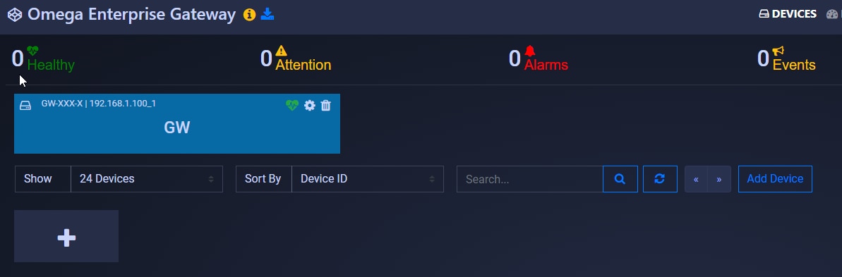
4.2 Adding a new Modbus device
The protocol converter I am going to implement will be polled by the gateway, so I need to add a new device. Unfortunately, the Omega gateway does not behave like a generic Modbus master. Instead, you can select among a finite list of supported Omega devices. As a consequence, the protocol converter will have to adapt and expose the set of Modbus registers the Omega gateway is expecting. If this approach makes sense from a commercial point of view, on the other hand it puts a limitation on the use of the Omega gateway as a platform for integrating a generic 3rd party Modbus device.
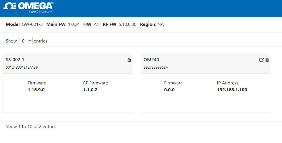
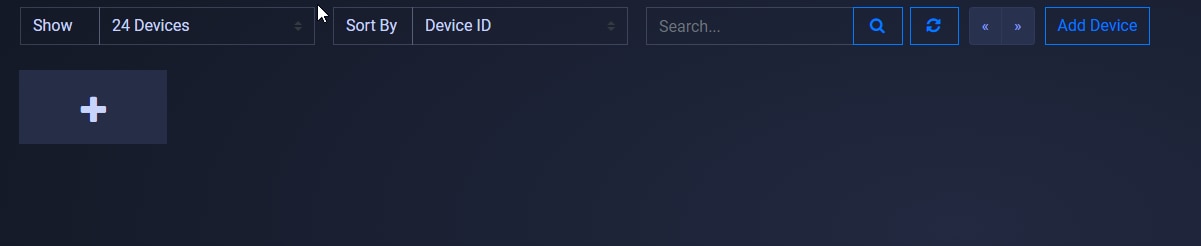
Let's proceed and add a new Modbus device. Click the "Add" button in the top right corner. The "Add device" form will popup.
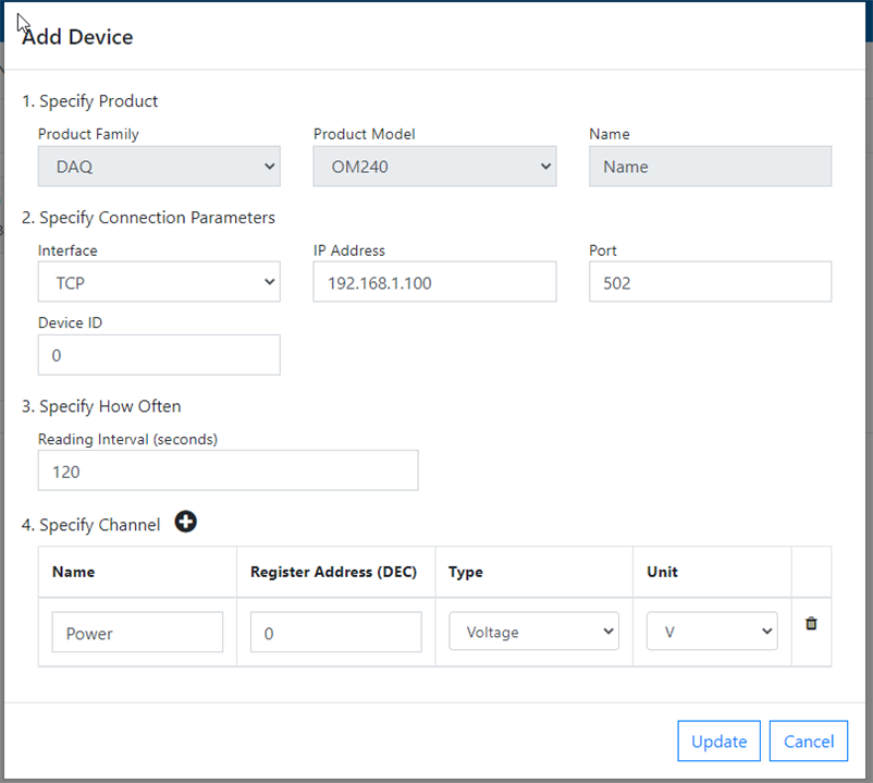
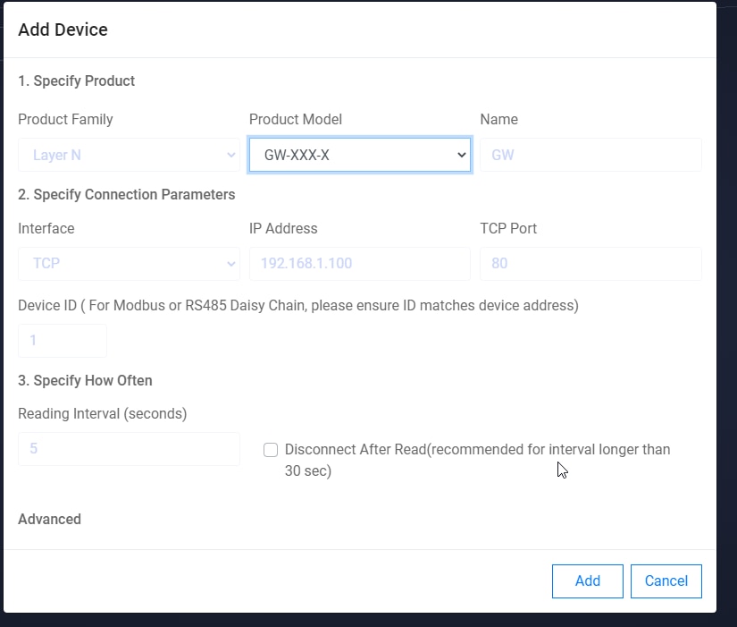
I filled the form with the following information
- Product family: This is the category the Omega device we want to integrate belongs to. Options include "Controller", "DAQ", "Meter" and "Probe". I selected "DAQ" because, in this category, there are devices that can be configured to monitor a range of physical quantities
- Product model: depending on the selected "Product family", the Omega products that match the category are listed. I selected "OM-240", an embedded data logger with 24 differential analog inputs. More information about the OM-240 can be found here
- Name: this is simply a string that you can use to easily identify the device
- Interface: I selected "TCP" because I want the protocol converter to be polled over my home Wifi network
- IP Address: this is the IP address of the protocol converter
- Port: this is the TCP port the protocol converter's Modbus server will be listening on. I left the default value (502)
- Device ID: this is the Modbus slave device Id. Any value is fine here, because my protocol converter will answer to all the requests
- Reading interval: this is how often the gateway will ask data to the protocol converter. 120 seconds (2 minutes) should be ok
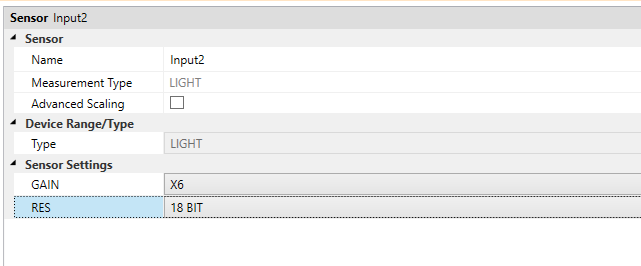
- Channel: this table contains the DAQ inputs we want to monitor. For each channel, you can enter a human-readable name, the Modbus register address (for OM240, this is calculated as 16 * <channel numer>), the type (i.e. the physical quantity you are measuring) and the unit of measure (which is automatically selected when you choose the type)