


2. Delta Solivia protocol description
Messages on the RS485-bus look like this:
| Size | Name | Value | Description |
| 1 byte | STX | 0x02 | Start of message |
| 1 byte | ENQ | Enquiry type (0x05 for requests, 0x06 for responses) | |
| 1 byte | Inverter ID | ||
| 1 byte | LEN | Number of bytes to follow, excluding CRC and ETX | |
| 2 bytes | CMD | command and subcommand e.g. 0x10 0x02 to request the current DC voltage, 0x10 0x02 to request the current DC current, etc. | |
| LEN-2 bytes | data bytes | ||
| 2 bytes | CRC | CRC-16, over preceding bytes excluding STX, LSB first (little-endian) | |
| 1 byte | ETX | 0x03 | End of message |


| Request | Response | Value | Meaning |
| [02][05][01][02][00][01][AD][FC][03] | [02][06][01][0C][00][01][30][30][30][30][30][30][37][38][39][34][2D][D0][03] | 0000007894 | Serial number |
| [02][05][01][02][10][02][E0][3D][03] | [02][06][01][04][10][02][01][88][32][E7][03] | 0x0188 | DC voltage (actual) |
| [02][05][01][02][11][02][E1][AD][03] | [02][06][01][04][11][02][01][78][33][5F][03] | 0x0178 | DC voltage (average) |
|
[02][05][01][02][10][01][A0][3C][03]
|
[02][06][01][04][10][01][00][09][03][17][03] | 0x0009 | DC current (actual). Unit is 0.1 A |
|
[02][05][01][02][11][01][A1][AC][03]
|
[02][06][01][04][11][01][00][05][02][EE][03] | 0x0005 | DC current (average). Unit is 0.1 A |
|
[02][05][01][02][11][03][20][6D][03]
|
[02][06][01][04][11][03][00][D7][23][73][03] | 0x00d7 | DC power |
|
[02][05][01][02][21][04][75][AF][03]
|
[02][06][01][04][21][04][07][D0][DE][40][03] | 0x07d0 | Isolation (actual, MOhm) |
|
[02][05][01][02][11][0F][20][68][03]
|
[02][06][01][04][11][0F][07][DA][20][85][03] | 0x07da | Isolation (average, MOhm) |
|
[02][05][01][02][10][08][60][3A][03]
|
[02][06][01][04][10][08][00][EC][12][9E][03] | 0x00ec | AC Voltage (actual) |
|
[02][05][01][02][11][08][61][AA][03]
|
[02][06][01][04][11][08][00][EA][93][60][03] | 0x00ea | AC Voltage (average) |
|
[02][05][01][02][10][07][20][3E][03]
|
[02][06][01][04][10][07][00][11][E3][1C][03] | 0x0011 | AC current (actual). Unit is 0.1 A |
|
[02][05][01][02][11][07][21][AE][03]
|
[02][06][01][04][11][07][00][0B][63][2B][03] | 0x000b | AC current (average). Unit is 0.1 A |
|
[02][05][01][02][10][09][A1][FA][03]
|
[02][06][01][04][10][09][01][72][C3][66][03] | 0x0172 | AC power (actual) |
|
[02][05][01][02][11][09][A0][6A][03]
|
[02][06][01][04][11][09][00][EE][C3][63][03] | 0x00ee | AC power (average) |
|
[02][05][01][02][21][06][F4][6E][03]
|
[02][06][01][04][21][06][00][1B][3C][27][03] | 0x001b | DC NTC Temperature |
|
[02][05][01][02][20][05][B5][FF][03]
|
[02][06][01][04][20][05][00][18][8D][DA][03] | 0x0018 | AC NTC Temperature |
| [02] | STX |
| [05] | ENQ |
| [01] | Inverter ID |
| [02] | Number of data bytes |
| [21][06] | Command and subcommand (DC NTC Temperature in this case) |
| [F4][6E] | CRC-16 |
| [03] | ETX |
| [02] | STX |
| [06] | RESPONSE |
| [01] | Inverter ID |
| [04] | Number of data bytes |
| [20][06] | Command and subcommand (the same of the request) |
| [00][1B] | 16-bit value of the requested parameter |
| [3C][27] | CRC-16 |
| [03] | ETX |
| Request | Response | Value | Meaning |
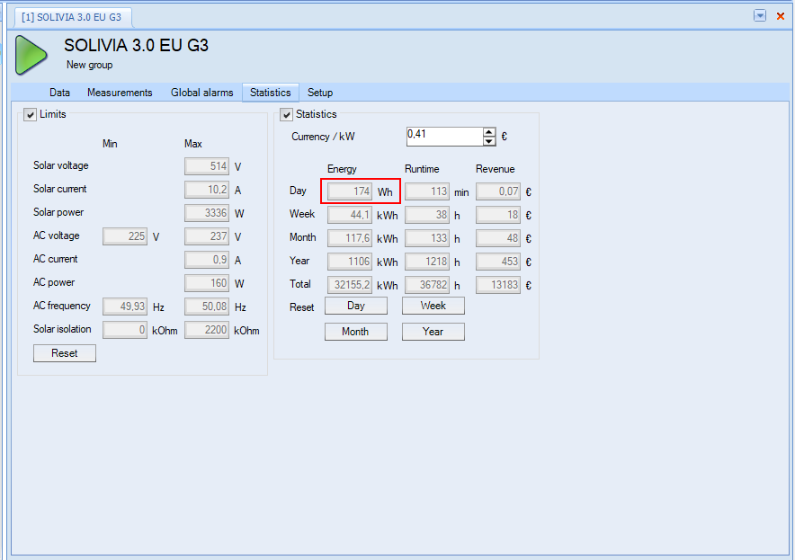
| [02][05][01][02][13][03][21][0D][03] | [02][06][01][04][13][03][00][AE][E3][29][02] | 0x00AE (174) | Daily yield (Wh) |
To implement the Delta Solivia protocol, I started from this project. I had to make some changes to use python3 (the library was written to support python2) and to use the correct commands.
Here is a brief description of the functions involved
3.1 solivia_readData
This function reads a specific value from the Delta Solivia inverter (DC power, AC power, etc). The only caveat here is that I had to add a check to remove some trailing 0xff characters that are probably mistakenly read by the USB-to-RS485 converter when inverter drives RS485 from RX to TX.
def solivia_readData(s):
    log.debug("Reading %s"%(s))

    cmd = solivia_inverter.getCmdStringFor(s)
    log.debug("Command: %s"%binascii.hexlify(cmd))
    solivia_connection.write(cmd)
    rawResponse = solivia_connection.read(100)

    cntr = 0
    while (cntr < len(rawResponse) and rawResponse[cntr] == 0xff):
       cntr += 1

    response = rawResponse[cntr:]

    floatValue = float("0")
    if response:
        log.debug("Received response %s\n"%binascii.hexlify(response))

        value = solivia_inverter.getValueFromResponse(response)
        #log.debug("Value %s"%value)
        if solivia_isFloat(value):
            floatValue = float(value)

    return floatValue
The code leverages functions in the deltaInv.py file to extract a value as a floating point number from the inverter response
3.2 solivia_updateChannel
This function updates all the Modbus registers required to mimic one of Omega OM240 channels. The following Modbus registers are initialized
- 2 16-bits registers with the value
- 8 16-bits registers with the timestamp string
- 1 16-bits registers with the flags
Here is the code
def solivia_updateChannel(ch, value, ts):
    """ Registers are as follow
    0-1 Input A (IEE754)
    2-3 Input B
    4-5 Temperature
    6-14 Timestamp "dd/mm/yy hh:mm:ss"
    15  Flags
    """
    vHex = solivia_floatToHex(value)[2:]
    log.debug("value=%f, vHex=%s"%(value,vHex))
    stime = ts.strftime("%d/%m/%y %H:%M:%S").encode('utf-8').hex().ljust(36, '0')

    values = [int(vHex[0:4],16), int(vHex[4:8],16),
                 0, 0,
                 0, 0,
              int(stime[0:4],16), int(stime[4:8],16), int(stime[8:12],16), int(stime[12:16],16), int(stime[16:20],16), int(stime[20:24],16), int(stime[24:28],16), int(stime[28:32],16), int(stime[32:36],16),
                 3]
    return values
3.3 solivia_reader
This functions reads all the measures and update the corresponding channels
def solivia_reader(a):
    """ A worker process that runs every so often and
    updates live values of the context. It should be noted
    that there is a race condition for the update.
    :param arguments: The input arguments to the call
    """
    log.info("Updating inverter data\n")

    dcVolts = solivia_readData('DC Volts1')
    dcCur = solivia_readData('DC Cur1')
    dcPow = solivia_readData('DC Pwr1')
    acVolts = solivia_readData('AC Volts')
    acCur = solivia_readData('AC Current')
    acPow = solivia_readData('AC Power')
    acTemp = solivia_readData('AC Temp')
    dcTemp = solivia_readData('DC Temp')

    context = a[0]
    register = 3
    slaveId = 0x00

    address = 0
    values = solivia_updateChannel(0, dcPow, datetime.now())
    context[slaveId].setValues(register, address, values)

    address = 16
    values = solivia_updateChannel(0, acPow, datetime.now())
    context[slaveId].setValues(register, address, values)

    address = 32
    values = solivia_updateChannel(0, acTemp, datetime.now())
    context[slaveId].setValues(register, address, values)

    address = 48
    values = solivia_updateChannel(0, dcTemp, datetime.now())
    context[slaveId].setValues(register, address, values)

    currDate = datetime.now().strftime("%d/%m/%y").encode('utf-8').hex().ljust(10, '0')
    currTime = datetime.now().strftime("%H:%M:%S").encode('utf-8').hex().ljust(8, '0')

    log.debug(currDate+"-"+currTime+" %.6f %.6f %.6f %.6f %.6f %.6f %.6f %.6f OK\n" %(dcVolts, dcCur, dcPow, acVolts, acCur, acPow, dcTemp, acTemp ))
    log.info("Scheduling task")
    time = 5.0
    loop = LoopingCall(f=solivia_reader, a=(context,))
loop.start(time, now=True) # initially delay by time #!/bin/sh
# launcher.sh
# navigate to home directory, then to this directory, then execute python script, then back home
cd /home/pi/nmodbus
sudo python3 server.py
cd /
# Edit this file to introduce tasks to be run by cron.
#
# Each task to run has to be defined through a single line
# indicating with different fields when the task will be run
# and what command to run for the task
#
# To define the time you can provide concrete values for
# minute (m), hour (h), day of month (dom), month (mon),
# and day of week (dow) or use '*' in these fields (for 'any').
#
# Notice that tasks will be started based on the cron's system
# daemon's notion of time and timezones.
#
# Output of the crontab jobs (including errors) is sent through
# email to the user the crontab file belongs to (unless redirected).
#
# For example, you can run a backup of all your user accounts
# at 5 a.m every week with:
# 0 5 * * 1 tar -zcf /var/backups/home.tgz /home/
#
# For more information see the manual pages of crontab(5) and cron(8)
#
# m h dom mon dow command
@reboot sh /home/pi/launcher.sh >/home/pi/logs/server.log 2>&1

