


- holding registers: these are "memory locations" that can store 16-bit values and can be read and written
- input registers: these are "memory locations" that can store 16-bit values and can only be read
- coils: these are "memory locations" that can store boolean values and can be read and written
- discrete inputs: these are "memory locations" that can store boolean values and can only be read
- 3: Read multiple holding registers
- 4: Read multiple input registers
- 6: Write single holding registers
- 16: Write multiple holding registers
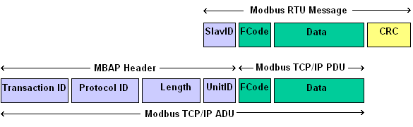
Modbus frames can be sent over different media. When sent over a serial (typically RS485) bus, frames adhere the Modbus RTU specification. When sent over a network cable, the Modbus TCP protocol is used. Modbus RTU and Modbus TCP are very similar: we can think Modbus TCP frame as a Modbus RTU frame with an extract header (called MBAP)
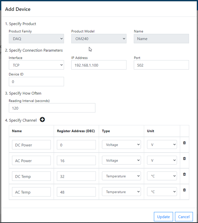
- Product family: This is the category the Omega device we want to integrate belongs to. I selected "DAQ" because, in this category, there are devices that can be configured to monitor a range of physical quantities
- Product model: I selected "OM240", an embedded data logger with 24 differential analog inputs
- Name: this is simply a string that you can use to easily identify the device. I left this filed empty
- Interface: I selected "TCP" because I want the protocol converter to be polled over my home Wifi network
- IP Address: this is the IP address of the protocol converter. I enter the static IP address of the protocol converter - 192.168.1.100
- Port: I left the default value (502), which the most commonly-used port for Modbus TCP communication
- Device ID: I entered 0, but any value is fine here, because my protocol converter will answer to all the requests
- Reading interval: this is how often the gateway will ask data to the protocol converter. 120 seconds (2 minutes) should be ok. Any value below this is useless because the Cloud N portal only accepts a refresh rate of up to 1 sample every 2 minutes
- Channel: this table contains the DAQ inputs we want to monitor. For each channel, you can enter a human-readable name, the Modbus register address (for OM240, this is calculated as 16 * <channel number>), the type (i.e. the physical quantity you are measuring) and the unit of measure (which is automatically selected when you choose the type). I added the following channels
- DC Power: power (in W) currently generated by the solar string (note that the "Add Device" form does not have an option for power-related measures, so I selected "Volts")
- AC Power: power (in W) currently sent to the grid. This is typically less the DC power because of the losses due to conversion from DC to AC
- DC Temperature: temperature reading of the inverter's internal NTC sensor on the "DC side"
- AC Temperature: temperature reading of the inverter's internal NTC sensor on the "AC side"
4. Modbus registers
As I said, protocol converter will pretend to be an OM240. Thankfully, there is manual with the OM240 memory map. In particular, it is stated that for each sensor (analogs, digitals, multiplexers and virtual channels), 16 registers will be exported, namely
- Input A’s last acquired measure (Offset 0-1)
- Input b (Offset 2-3)
- sensor’s temperature (Offset 4-5)
- Acquisition’s timestamp (Offset 6-7-8-9-10-11-12-13-14)
- flags to show acquisition status and alarm status (Offset 15).
- bit 0: Sensor acquired
- bit 1: A valid Input
- bit 2: B valid Input
- bit 3: Valid Temp input
- bit 4: A alarm Input
- bit 5: B alarm Input
- bit 6: Temp alarm Input
According to my test, the timestamp is actually ignored and the timestamp of the gateway (most probably) or the cloud server is used
- store the value in registers at offset 0 (MSB) and 1 (LSB)
- set flags register (at offset 15) to 3 (sensor acquired and input A valid)
5. Modbus implementation
The implementation is based on PyModbus library
To install the PyModbus library, you just have to use pip3 for PyModbus and Twister
pip3 install pymodbus
pip3 install twister
Then the implementation of the Modbus server is quite straightforward
The Omega gateway is the master in the Modbus communication, so the protocol converter needs to act as a slave (or server), meaning that it will sit waiting for requests from the gateway. Three steps are required to initialize the Modbus server
5.1 Initialize data store
Data store is where PyModbus library stores the values it will responds to the Modbus master.
First of all, we need to define one or more data block. To define a data block, the ModbusSequentialDataBlock or ModbusSparseDataBlock functions are used. The difference is that the sequential has no gaps in the data while the sparse can
block = ModbusSequentialDataBlock(0x00, [0]*0xff)
block = ModbusSparseDataBlock({0x00: 0, 0x05: 1})
The first line of code creates a data block of 255 (0xff) elements starting from address 0x00. The second one creates two elements: one at address 0x00 initialized with value 0 and one at address 0x05 initialized with value 1Then, you can combine data blocks in a data store
store = ModbusSlaveContext(
    di=ModbusSequentialDataBlock(0, [17] * 100),
    co=ModbusSequentialDataBlock(0, [17] * 100),
    hr=ModbusSequentialDataBlock(0, [17] * 100),
    ir=ModbusSequentialDataBlock(0, [17] * 100))
The ModbusSlaveContext accepts a "slaves" parameter where you can define a list of unit ids the server will respond. Since we omitted that parameter, the server will respond to all the requests, thus ignoring the value of unit id
Also note that datastores only respond to the addresses that they are initialized to, therefore, if you initialize a data block to addresses of 0x00 to 0xFF, a request to 0x100 will respond with an invalid address exception.
5.2 Initialize server information
You can configure some information about server that can eventually be queried by the Modbus master. I am not interested in this information, so I copied-and-pasted the values from one of the examples
identity = ModbusDeviceIdentification()
identity.VendorName = 'Pymodbus'
identity.ProductCode = 'PM'
identity.VendorUrl = 'http://github.com/riptideio/pymodbus/'
identity.ProductName = 'Pymodbus Server'
identity.ModelName = 'Pymodbus Server'
identity.MajorMinorRevision = version.short()
5.3 Start the server
The Modbus server can now be launched. Several modes are supported (TCP, UDP, with TLS support, with different framers). To talk with the gateway, I need a basic server talking on a TCP channel
StartTcpServer(context, identity=identity, address=("", 502))
5.4 Initialization code
This is the full Modbus server initialization code
def run_server():
    # ----------------------------------------------------------------------- #
    # initialize data store
    # ----------------------------------------------------------------------- #
    store = ModbusSlaveContext(
        di=ModbusSequentialDataBlock(0, [0] * 100),
        co=ModbusSequentialDataBlock(0, [0] * 0xffff),
        hr=ModbusSequentialDataBlock(0, [0] * 0xffff),
        ir=ModbusSequentialDataBlock(0, [0] * 100))

    context = ModbusServerContext(slaves=store, single=True)

    # ----------------------------------------------------------------------- #
    # initialize the server information
    # ----------------------------------------------------------------------- #
    # If you don't set this or any fields, they are defaulted to empty strings.
    # ----------------------------------------------------------------------- #
    identity = ModbusDeviceIdentification()
    identity.VendorName = 'Pymodbus'
    identity.ProductCode = 'PM'
    identity.VendorUrl = 'http://github.com/riptideio/pymodbus/'
    identity.ProductName = 'Pymodbus Server'
    identity.ModelName = 'Pymodbus Server'
    identity.MajorMinorRevision = version.short()

    # ----------------------------------------------------------------------- #
    # run the TCP server
    # ----------------------------------------------------------------------- #
    log.info("Starting server")
    StartTcpServer(context, identity=identity, address=("", 502))
That's all for this post. In the next episode, I will talk about what's on the other side of the protocol converter: the Delta Solivia proprietary protocol