element14 Community
element14 Community
    Register Log In
  • Site
  • Search
  • Log In Register
  • About Us
  • Community Hub
    Community Hub
    • What's New on element14
    • Feedback and Support
    • Benefits of Membership
    • Personal Blogs
    • Members Area
    • Achievement Levels
  • Learn
    Learn
    • Ask an Expert
    • eBooks
    • element14 presents
    • Learning Center
    • Tech Spotlight
    • STEM Academy
    • Webinars, Training and Events
    • Learning Groups
  • Technologies
    Technologies
    • 3D Printing
    • FPGA
    • Industrial Automation
    • Internet of Things
    • Power & Energy
    • Sensors
    • Technology Groups
  • Challenges & Projects
    Challenges & Projects
    • Design Challenges
    • element14 presents Projects
    • Project14
    • Arduino Projects
    • Raspberry Pi Projects
    • Project Groups
  • Products
    Products
    • Arduino
    • Avnet Boards Community
    • Dev Tools
    • Manufacturers
    • Multicomp Pro
    • Product Groups
    • Raspberry Pi
    • RoadTests & Reviews
  • Store
    Store
    • Visit Your Store
    • Choose another store...
      • Europe
      •  Austria (German)
      •  Belgium (Dutch, French)
      •  Bulgaria (Bulgarian)
      •  Czech Republic (Czech)
      •  Denmark (Danish)
      •  Estonia (Estonian)
      •  Finland (Finnish)
      •  France (French)
      •  Germany (German)
      •  Hungary (Hungarian)
      •  Ireland
      •  Israel
      •  Italy (Italian)
      •  Latvia (Latvian)
      •  
      •  Lithuania (Lithuanian)
      •  Netherlands (Dutch)
      •  Norway (Norwegian)
      •  Poland (Polish)
      •  Portugal (Portuguese)
      •  Romania (Romanian)
      •  Russia (Russian)
      •  Slovakia (Slovak)
      •  Slovenia (Slovenian)
      •  Spain (Spanish)
      •  Sweden (Swedish)
      •  Switzerland(German, French)
      •  Turkey (Turkish)
      •  United Kingdom
      • Asia Pacific
      •  Australia
      •  China
      •  Hong Kong
      •  India
      •  Korea (Korean)
      •  Malaysia
      •  New Zealand
      •  Philippines
      •  Singapore
      •  Taiwan
      •  Thailand (Thai)
      • Americas
      •  Brazil (Portuguese)
      •  Canada
      •  Mexico (Spanish)
      •  United States
      Can't find the country/region you're looking for? Visit our export site or find a local distributor.
  • Translate
  • Profile
  • Settings
Safe and Sound
  • Challenges & Projects
  • Design Challenges
  • Safe and Sound
  • More
  • Cancel
Safe and Sound
Blog MSP432 and TI-RTOS: PWM
  • Blog
  • Forum
  • Documents
  • Polls
  • Files
  • Events
  • Mentions
  • Sub-Groups
  • Tags
  • More
  • Cancel
  • New
  • Share
  • More
  • Cancel
Group Actions
  • Group RSS
  • More
  • Cancel
Engagement
  • Author Author: Jan Cumps
  • Date Created: 2 Jan 2017 8:49 AM Date Created
  • Views 1986 views
  • Likes 8 likes
  • Comments 4 comments
  • safe and sound
  • pwm
  • rtos
  • msp432
  • ti-rtos
  • launchpad
  • feature_tutorial
  • ti_rt
Related
Recommended

MSP432 and TI-RTOS: PWM

Jan Cumps
Jan Cumps
2 Jan 2017

How to get at the PWM signals of the MSP432 LaunchPad with TI-RTOS

image

The TI-RTOS examples for the MSP432 LaunchPad all route the PWM signals to an RGB LED. That's ideal for examples. But what if you need the signals for something else?

This blog shows how to connect PWM output to BoosterPack connector pins.


What you need:

  • MSP432 LaunchPad
  • 1 micro-USB cable
  • Code Composer Studio
  • TI-RTOS for MSP43X


For your project, you may need PWM signals to control a motor, drive external LEDs, ...

By default, if you use TI-RTOS projects, there are two PWM sources defined. They both are linked to the on-board RGB LED.

To give your project PWM signals, it would be great to get them linked to pins on the BoosterPack connectors.


There's more than one way to get PWM access on those BoosterPack connectors.

We could add additional PWM definitions and leave the on-board RGB LED connected.

For this example I've taken another path: switch the existing PWM0 and PWM1 signal away from the RGB LED and route them to BoosterPack connector J4.


I'm choosing the second and third pin on P4, P2.6 and P2.4. You are free to choose other GPIO pins.


image


Start by loading the TI-RTOS PWM LED example. It's available via Resource Explorer, under the Driver examples for your LaunchPad.

Follow these steps to import the project:

Start Code Composer Studio.

Menu View -> Resource Explorer

Navigate to TI-RTOS for MSP43x -> Development Tools -> MSP-EXP432x -> PWM Examples -> PWM LED Example


Build and Run the example. You should see the RGB LED gradually increase brightness until maximum.


If you'd put a scope on the two rightmost jumpers above the LED, you 'd see signals like this, with a continuously changing duty cycle:

image

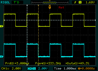
It's those signals that we want to move to the two BoosterPack pins.

All the work is done in the source file MSP_EXP432P401R.c.


We have to make two changes. The first one is to make P2.6 and P2.4 PWM pins, instead of the LED-connected pins P2.1 and P2.2


const PWMTimerMSP432_HWAttrsV1 pwmTimerMSP432HWAttrs[MSP_EXP432P401R_PWMCOUNT] = {
    {
        .timerBaseAddr = TIMER_A1_BASE,
        .clockSource = TIMER_A_CLOCKSOURCE_SMCLK,
        .compareRegister = TIMER_A_CAPTURECOMPARE_REGISTER_1,
        .gpioPort = GPIO_PORT_P2,
        .gpioPinIndex = GPIO_PIN6,
        .pwmMode = GPIO_PRIMARY_MODULE_FUNCTION
    },
    {
        .timerBaseAddr = TIMER_A1_BASE,
        .clockSource = TIMER_A_CLOCKSOURCE_SMCLK,
        .compareRegister = TIMER_A_CAPTURECOMPARE_REGISTER_2,
        .gpioPort = GPIO_PORT_P2,
        .gpioPinIndex = GPIO_PIN4,
        .pwmMode = GPIO_PRIMARY_MODULE_FUNCTION
    }
};


Then change the PWM port map for GPIO port 2. Connect timer signal TA1CCR1A to 2.6, 2A to P2.4.

You do that by setting in the map to what bit (= pin) of the port each of those signals goes.


/*
 *  ======== MSP_EXP432P401R_initPWM ========
 */
void MSP_EXP432P401R_initPWM(void)
{
    /* Use Port Map on Port2 get Timer outputs on pins 2.4, 2.6) */
    /* this is different then the standard mapping for the Launchpad
     * that puts Timer outputs on pins with LEDs (2.1, 2.2)
     * Board_PWM0 mapped to 2.6
     * Board_PWM1 mapped to 2.4
     */
    const uint8_t portMap [] = {
        PM_NONE, PM_NONE, PM_NONE, PM_NONE,
        PM_TA1CCR2A, PM_NONE, PM_TA1CCR1A, PM_NONE
    };

    /* Mapping capture compare registers to Port 2 */
    MAP_PMAP_configurePorts((const uint8_t *) portMap, PMAP_P2MAP, 1,
        PMAP_DISABLE_RECONFIGURATION);

    PWM_init();
}


If you now Build and Run the program, the LED will no longer blink. You'll find your 2 PWM signals back on BoosterPack connector J2, P2.6 and P2.4.

You can check this with a logic analyzer or a scope, as in the picture below:


image


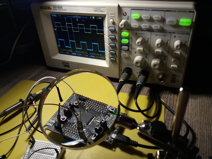
You can now use these signals to drive your project.


TI-RTOS Series
MSP432 and TI-RTOS: Getting Started Pt. 1 - Set Up and 1st RTOS Task
MSP432 and TI-RTOS: Getting Started Pt. 2 - Add an ADC Sample Task
MSP432 and TI-RTOS: Getting Started Pt. 3 - USB with Minimal CPU Use
MSP432 and TI-RTOS: PWM
MSP432 and TI-RTOS: I2C Configuration for Sensors BoosterPack
MSP432 and TI-RTOS: another I2C example - talk to a DAC
MSP432 and TI-RTOS: Sharp LCD BoosterPack
MSP432 and TI-RTOS: PID Library Part 1 - Intro
MSP432 and TI-RTOS: PID Library Part 2 - Real World Example
  • Sign in to reply

Top Comments

  • Jan Cumps
    Jan Cumps over 8 years ago in reply to clem57 +2
    I haven't looked into the SPI lib yet, but when I check the initialisation code, it looks promising: /* CLK, MOSI & MISO ports & pins */ .portSCK = GPIO_PORT_P1, .pinSCK = GPIO_PIN5, .sckMode = GPIO_PRIMARY_MODULE_FUNCTION…
  • Jan Cumps
    Jan Cumps over 8 years ago in reply to Jan Cumps +2
    I 'll have to revoke the SPI pins can be reallocated. I tried and couldn't get it to work. In retrospect, it seems that the pins for the serial universal peripherals are fixed.
  • DAB
    DAB over 8 years ago +1
    Nice post. I like your ease in to explaining RTOS and providing good pictures. Well done. DAB
  • Jan Cumps
    Jan Cumps over 8 years ago in reply to Jan Cumps

    I 'll have to revoke the SPI pins can be reallocated. I tried and couldn't get it to work.

    In retrospect, it seems that the pins for the serial universal peripherals are fixed.

    • Cancel
    • Vote Up +2 Vote Down
    • Sign in to reply
    • More
    • Cancel
  • DAB
    DAB over 8 years ago

    Nice post.


    I like your ease in to explaining RTOS and providing good pictures.


    Well done.


    DAB

    • Cancel
    • Vote Up +1 Vote Down
    • Sign in to reply
    • More
    • Cancel
  • Jan Cumps
    Jan Cumps over 8 years ago in reply to clem57

    I haven't looked into the SPI lib yet, but when I check the initialisation code, it looks promising:


            /* CLK, MOSI & MISO ports & pins */
            .portSCK = GPIO_PORT_P1,
            .pinSCK = GPIO_PIN5,
            .sckMode = GPIO_PRIMARY_MODULE_FUNCTION,
    
            .portMISO = GPIO_PORT_P1,
            .pinMISO = GPIO_PIN7,
            .misoMode = GPIO_PRIMARY_MODULE_FUNCTION,
    
            .portMOSI = GPIO_PORT_P1,
            .pinMOSI = GPIO_PIN6,
            .mosiMode = GPIO_PRIMARY_MODULE_FUNCTION,
    
            /* Chip select port & pin */
            .portCS = GPIO_PORT_P4,
            .pinCS = GPIO_PIN6


    edit: I bet I'm wrong.

    • Cancel
    • Vote Up +2 Vote Down
    • Sign in to reply
    • More
    • Cancel
  • clem57
    clem57 over 8 years ago

    Thanks Jan Cumps for explaining how to move the PWM's to other GPIO pins. Can I assume other pin assignments can move as well like SPI for example?

    Clem

    • Cancel
    • Vote Up 0 Vote Down
    • Sign in to reply
    • More
    • Cancel
element14 Community

element14 is the first online community specifically for engineers. Connect with your peers and get expert answers to your questions.

  • Members
  • Learn
  • Technologies
  • Challenges & Projects
  • Products
  • Store
  • About Us
  • Feedback & Support
  • FAQs
  • Terms of Use
  • Privacy Policy
  • Legal and Copyright Notices
  • Sitemap
  • Cookies

An Avnet Company © 2025 Premier Farnell Limited. All Rights Reserved.

Premier Farnell Ltd, registered in England and Wales (no 00876412), registered office: Farnell House, Forge Lane, Leeds LS12 2NE.

ICP 备案号 10220084.

Follow element14

  • X
  • Facebook
  • linkedin
  • YouTube