element14 Community
element14 Community
    Register Log In
  • Site
  • Search
  • Log In Register
  • About Us
  • Community Hub
    Community Hub
    • What's New on element14
    • Feedback and Support
    • Benefits of Membership
    • Personal Blogs
    • Members Area
    • Achievement Levels
  • Learn
    Learn
    • Ask an Expert
    • eBooks
    • element14 presents
    • Learning Center
    • Tech Spotlight
    • STEM Academy
    • Webinars, Training and Events
    • Learning Groups
  • Technologies
    Technologies
    • 3D Printing
    • FPGA
    • Industrial Automation
    • Internet of Things
    • Power & Energy
    • Sensors
    • Technology Groups
  • Challenges & Projects
    Challenges & Projects
    • Design Challenges
    • element14 presents Projects
    • Project14
    • Arduino Projects
    • Raspberry Pi Projects
    • Project Groups
  • Products
    Products
    • Arduino
    • Avnet Boards Community
    • Dev Tools
    • Manufacturers
    • Multicomp Pro
    • Product Groups
    • Raspberry Pi
    • RoadTests & Reviews
  • Store
    Store
    • Visit Your Store
    • Choose another store...
      • Europe
      •  Austria (German)
      •  Belgium (Dutch, French)
      •  Bulgaria (Bulgarian)
      •  Czech Republic (Czech)
      •  Denmark (Danish)
      •  Estonia (Estonian)
      •  Finland (Finnish)
      •  France (French)
      •  Germany (German)
      •  Hungary (Hungarian)
      •  Ireland
      •  Israel
      •  Italy (Italian)
      •  Latvia (Latvian)
      •  
      •  Lithuania (Lithuanian)
      •  Netherlands (Dutch)
      •  Norway (Norwegian)
      •  Poland (Polish)
      •  Portugal (Portuguese)
      •  Romania (Romanian)
      •  Russia (Russian)
      •  Slovakia (Slovak)
      •  Slovenia (Slovenian)
      •  Spain (Spanish)
      •  Sweden (Swedish)
      •  Switzerland(German, French)
      •  Turkey (Turkish)
      •  United Kingdom
      • Asia Pacific
      •  Australia
      •  China
      •  Hong Kong
      •  India
      •  Korea (Korean)
      •  Malaysia
      •  New Zealand
      •  Philippines
      •  Singapore
      •  Taiwan
      •  Thailand (Thai)
      • Americas
      •  Brazil (Portuguese)
      •  Canada
      •  Mexico (Spanish)
      •  United States
      Can't find the country/region you're looking for? Visit our export site or find a local distributor.
  • Translate
  • Profile
  • Settings
Safe and Sound
  • Challenges & Projects
  • Design Challenges
  • Safe and Sound
  • More
  • Cancel
Safe and Sound
Blog MSP432 and TI-RTOS: Getting Started Pt. 3 - USB with Minimal CPU Use
  • Blog
  • Forum
  • Documents
  • Polls
  • Files
  • Events
  • Mentions
  • Sub-Groups
  • Tags
  • More
  • Cancel
  • New
  • Share
  • More
  • Cancel
Group Actions
  • Group RSS
  • More
  • Cancel
Engagement
  • Author Author: Jan Cumps
  • Date Created: 17 Feb 2017 9:51 PM Date Created
  • Views 3315 views
  • Likes 6 likes
  • Comments 17 comments
  • msp432_launchpad
  • usb
  • uart
  • msp432
  • ti_rt
Related
Recommended

MSP432 and TI-RTOS: Getting Started Pt. 3 - USB with Minimal CPU Use

Jan Cumps
Jan Cumps
17 Feb 2017

Part 3 in a series that gets you RTOS-ready for the MSP432 LaunchPad


image


When you complete this example, you have a basic RTOS setup that integrates USB, ADC and a blinky. You can use Tasks, Semaphores and a UART interrupt. And you'll know how to register Tasks in the TI-RTOS configuration editor.


Part 1 sets up the project, explains how to configure a task and gets the Blinky running.

Part 2 adds an ADC Sample Task.

Part 3 enables USB without silly loops when waiting for traffic.


What you need:

  • MSP432 LaunchPad
  • 1 micro-USB cable
  • Code Composer Studio
  • TI-RTOS for MSP43X


A few design assumptions:

In our scenario we need each character immediately. We don't wait for any end of line, CR, LF or whatever character. The code can be easily adapted to do that if you want it.

We'll use an interrupt to sense incoming data

The output to USB is straightforward streamed. We assume that all the data is ready in some array when it's time to send it. Again other scenarios can be buid, but we don't do that here.


Wait for Data in RTOS without Processor Overhead

It's a standard functionality of the framework. In TI-RTOS, you can make a task inactive until something happens.

That can be the scheduler waking up, or - in our case - a message being sent from an interrupt when data arrives on the USB port.

This solution takes care that your firmware can spend its focus on actual work while there's no data arriving at the port. With liitle effort from your side.


You'll need

  • an RTOS task that initialises the USB peripheral and waits for data.
  • an interrupt handler that gives that task a kick when there's a character appearing on the USB bus receive line.


The USB Task and Semaphores

Unlike other RTOS tasks, this one doesn't need a schedule. It's not woken by a scheduler but by an message coming from an interrupt.

The technique we're using is a binary semaphore. This is a technique where you can make one thing wait for something else to happen.

The waiting doesn't cost. It's handled in the limited overhead computing use of the TI-RTOS, the same chunk of code that handles scheduling and prioritisation.


In our task, we initialise the USB (UART) driver and tell it that we want to use an interrupt when data arrives.

We also prepare the semaphore (inactivate + wait) mechanism that we'll use later when the program is ready for business.


#include <uart_impl.h>
UART_Handle uart;

Semaphore_Handle SEM_uart_rx; // this binary semaphore handles uart receiving interrupts
void UART00_IRQHandler(UART_Handle handle, void *buffer, size_t num);

/*
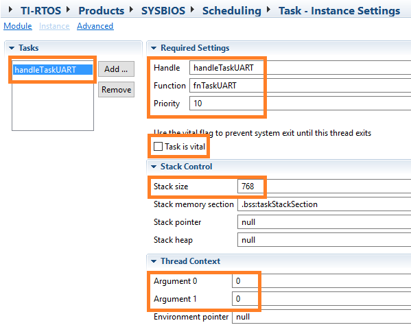
 *  ======== fnTaskUART ========
 *  Task for this function is created statically. See the project's .cfg file.
 */
Void fnTaskUART(UArg arg0, UArg arg1)
{
    char input;
    UART_Params uartParams;
    Error_Block eb;
    Semaphore_Params sem_params;


    /* Create a UART with data processing off. */
    UART_Params_init(&uartParams);
    uartParams.writeDataMode = UART_DATA_BINARY;
    uartParams.readDataMode = UART_DATA_BINARY;
    uartParams.readReturnMode = UART_RETURN_FULL;
    uartParams.readEcho = UART_ECHO_OFF;
    uartParams.baudRate = 9600;
    uartParams.readMode = UART_MODE_CALLBACK; // the uart uses a read interrupt
    uartParams.readCallback = &UART00_IRQHandler; // function called when the uart interrupt fires
    uart = UART_open(Board_UART0, &uartParams);


    if (uart == NULL) {
        System_abort("Error opening the UART");
    }

    Semaphore_Params_init(&sem_params);
    sem_params.mode = Semaphore_Mode_BINARY;

    SEM_uart_rx = Semaphore_create(0, &sem_params, &eb);


The part that tells the RTOS that we'll use an interrupt is:


    uartParams.readMode = UART_MODE_CALLBACK; // the uart uses a read interrupt
    uartParams.readCallback = &UART00_IRQHandler; // function called when the uart interrupt fires


Then we'll go into a loop that primes the USB driver so that it's ready for incoming data, then sleeps until data arrives.

When a character arrives, our interrupt handler (see next section) wakes us up. We hand over the character to the firmware function that needs it.

Then we repeat priming the USB driver and back to sleep. Until the battery runs out image.


    while (1) {
        UART_read(uart, &input, 1); // prime the uart bus to read the first character, non blocking
        Semaphore_pend(SEM_uart_rx, BIOS_WAIT_FOREVER); // when a character is received via UART, the interrupt handler will release the binary semaphore
        // in my case: I get an interrupt for a single character, no need to loop.
        GPIO_toggle(Board_LED1); // LED B - visual clue that we've received a request over USB
       ___SEND_CHAR_TO_YOUR_LOGIC((const char *)&input, 1);
        GPIO_toggle(Board_LED1); // LED B - visual clue off
    }
}


Because we told the USB driver that we're working with callback, the UART_read(1) call will immediately return without data, but it'll tell the driver to call the interrupt handler when 1 character arrives.

(if you don't tell the driver that you're using callbacks, the UART_read() function blocks until there's a character)

The Semaphore_pend() then makes the semaphore block and wait - without burning cpu cycles - until the interrupt releases that semaphore.

When that happens, we toggle a led (yeah, I know), send the character that was sent to the USB port to our code (replace ___SEND_CHAR_TO_YOUR_LOGIC() with your real function that needs the input. Maybe a command parser?)

We toggle that led again ( image ) and then reset the port and sleep.

Over and over again.


image


The USB Input Interrupt Handler

You will have seen a glimps of it twice in the previous code chunks.

We've put a forward definition of it at the start of our oce (because in my case, I've put it in the source file after the first use location in the RTOS task.

Then we see it again in the UART driver initialisation:


void UART00_IRQHandler(UART_Handle handle, void *buffer, size_t num);
  // ...
    uartParams.readCallback = &UART00_IRQHandler; // function called when the uart interrupt fires


The code itself:


/* EUSCI A0 UART ISR - The interrupt handler fr UART0 (USB)
 * this method releases the TI-RTOS binary semaphore SEM_uart_rx
 * and uartFxn() will process the received c
 */

void UART00_IRQHandler(UART_Handle handle, void *buffer, size_t num)
{
    Semaphore_post(SEM_uart_rx);
}


Very very straightforward. When a character arrives on the USB input, a trigger fires (because we put the driver in callback mode).

The trigger calls UART00_IRQHandler() (because we've told the driver that this is the interrupt service method).

UART00_IRQHandler() then releases the semaphore lock.

That action is enough to wake up that sleeping task and let it consume the character.


Varia

(thank you fmilburn)


Includes needed:

#include <xdc/runtime/Error.h>
#include <ti/sysbios/knl/Semaphore.h>
#include <ti/drivers/UART.h>


Initialisation of UART in main():

    Board_initUART();


A working CCS project is attached to this blog post.

The project echos back each character it receives on the input.

To test, connect to the USB serial port with a terminal program, serial, 9600, 8, 1 N

Check usb_test.c for the code, usb_tes.cfg for the task instantiation.


If you look at this code and understand it, you've learned a few more advanced RTOS principles: Semaphores and interrupt handling.

Additional bonus: when you don't have any other tasks to run during the wait, RTOS will put the controller in a lo power mode. WIN-WINCopyright.


TI-RTOS Series
MSP432 and TI-RTOS: Getting Started Pt. 1 - Set Up and 1st RTOS Task
MSP432 and TI-RTOS: Getting Started Pt. 2 - Add an ADC Sample Task
MSP432 and TI-RTOS: Getting Started Pt. 3 - USB with Minimal CPU Use
MSP432 and TI-RTOS: PWM
MSP432 and TI-RTOS: I2C Configuration for Sensors BoosterPack
MSP432 and TI-RTOS: another I2C example - talk to a DAC
MSP432 and TI-RTOS: Sharp LCD BoosterPack
MSP432 and TI-RTOS: PID Library Part 1 - Intro
MSP432 and TI-RTOS: PID Library Part 2 - Real World Example
Attachments:
MSP432_TIRTOS_USB_TEST.zip
  • Sign in to reply

Top Comments

  • jc2048
    jc2048 over 8 years ago +3
  • Jan Cumps
    Jan Cumps over 8 years ago in reply to fmilburn +3
    Things I forgot: #include <xdc/runtime/Error.h> #include <ti/sysbios/knl/Semaphore.h> #include <ti/drivers/UART.h> Board_initUART(); I'll upload a zipped working CCS project to the original post, that…
  • clem57
    clem57 over 8 years ago +1
    This looks handy for a way to handle USB tasks.
  • jomoenginer
    jomoenginer over 8 years ago in reply to Jan Cumps

    Jan,


    Yeah, it looks like it was on my end.  I updated the ARM Compiler and it now shows TI v16.12.0 and the project imports fine.  From the list of compilers list in CCS7, it appears I had v16.9.0 previously. I did go through an update recently, but it took going through CCS App Center to get the updated ARM compiler loaded.


    Thanks,


    Jon

    • Cancel
    • Vote Up 0 Vote Down
    • Sign in to reply
    • More
    • Cancel
  • jomoenginer
    jomoenginer over 8 years ago in reply to Jan Cumps

    Jan,


      I have other MSP432 TI-RTOS projects that work fine and I am sure I can create a  new Empty project just fine, it's just when I attempt to import the project that you posted in the .zip file that I see the error with.  I see this with an updated CCS 7 as well as CCS 6.

    The odd thing is that it adds the project folder to the workspace but CCS refuses to import the project in to my project list.  Strange.


    I'll have a look at this a bit more to see if I am missing anything.

    • Cancel
    • Vote Up +1 Vote Down
    • Sign in to reply
    • More
    • Cancel
  • Jan Cumps
    Jan Cumps over 8 years ago in reply to fmilburn

    For some reason, this is the compiler that CCS sets when I start a MSP project:

    image


    I have several toolchains on my PC, Arm and others. It may be that my install is off.....

    • Cancel
    • Vote Up 0 Vote Down
    • Sign in to reply
    • More
    • Cancel
  • jomoenginer
    jomoenginer over 8 years ago in reply to fmilburn

    Frank,


    The error comes from the Import of the project. I have other MSP432 projects that run fine, but it seem to have an issue when I attempt to import the project that was posted to this example.

    • Cancel
    • Vote Up +1 Vote Down
    • Sign in to reply
    • More
    • Cancel
  • Jan Cumps
    Jan Cumps over 8 years ago in reply to jomoenginer

    I should have the latest of the latest, jomoenginer. I've just installed a fresh CCS  and compilers.

    If you have difficulties, just start a new TI-RTOS Empty project on your install. Remove empty.c and empty.cfg, and copy the usb_test.c and usb_test.cfg from my project in your project root.

    (after doing that, check if usb_test.cfg isn't excluded from compile. CSS likes to do that with TI-RTOS config files you paste into a project)

    • Cancel
    • Vote Up 0 Vote Down
    • Sign in to reply
    • More
    • Cancel
>
element14 Community

element14 is the first online community specifically for engineers. Connect with your peers and get expert answers to your questions.

  • Members
  • Learn
  • Technologies
  • Challenges & Projects
  • Products
  • Store
  • About Us
  • Feedback & Support
  • FAQs
  • Terms of Use
  • Privacy Policy
  • Legal and Copyright Notices
  • Sitemap
  • Cookies

An Avnet Company © 2025 Premier Farnell Limited. All Rights Reserved.

Premier Farnell Ltd, registered in England and Wales (no 00876412), registered office: Farnell House, Forge Lane, Leeds LS12 2NE.

ICP 备案号 10220084.

Follow element14

  • X
  • Facebook
  • linkedin
  • YouTube