element14 Community
element14 Community
    Register Log In
  • Site
  • Search
  • Log In Register
  • Community Hub
    Community Hub
    • What's New on element14
    • Feedback and Support
    • Benefits of Membership
    • Personal Blogs
    • Members Area
    • Achievement Levels
  • Learn
    Learn
    • Ask an Expert
    • eBooks
    • element14 presents
    • Learning Center
    • Tech Spotlight
    • STEM Academy
    • Webinars, Training and Events
    • Learning Groups
  • Technologies
    Technologies
    • 3D Printing
    • FPGA
    • Industrial Automation
    • Internet of Things
    • Power & Energy
    • Sensors
    • Technology Groups
  • Challenges & Projects
    Challenges & Projects
    • Design Challenges
    • element14 presents Projects
    • Project14
    • Arduino Projects
    • Raspberry Pi Projects
    • Project Groups
  • Products
    Products
    • Arduino
    • Avnet Boards Community
    • Dev Tools
    • Manufacturers
    • Multicomp Pro
    • Product Groups
    • Raspberry Pi
    • RoadTests & Reviews
  • Store
    Store
    • Visit Your Store
    • Choose another store...
      • Europe
      •  Austria (German)
      •  Belgium (Dutch, French)
      •  Bulgaria (Bulgarian)
      •  Czech Republic (Czech)
      •  Denmark (Danish)
      •  Estonia (Estonian)
      •  Finland (Finnish)
      •  France (French)
      •  Germany (German)
      •  Hungary (Hungarian)
      •  Ireland
      •  Israel
      •  Italy (Italian)
      •  Latvia (Latvian)
      •  
      •  Lithuania (Lithuanian)
      •  Netherlands (Dutch)
      •  Norway (Norwegian)
      •  Poland (Polish)
      •  Portugal (Portuguese)
      •  Romania (Romanian)
      •  Russia (Russian)
      •  Slovakia (Slovak)
      •  Slovenia (Slovenian)
      •  Spain (Spanish)
      •  Sweden (Swedish)
      •  Switzerland(German, French)
      •  Turkey (Turkish)
      •  United Kingdom
      • Asia Pacific
      •  Australia
      •  China
      •  Hong Kong
      •  India
      •  Korea (Korean)
      •  Malaysia
      •  New Zealand
      •  Philippines
      •  Singapore
      •  Taiwan
      •  Thailand (Thai)
      • Americas
      •  Brazil (Portuguese)
      •  Canada
      •  Mexico (Spanish)
      •  United States
      Can't find the country/region you're looking for? Visit our export site or find a local distributor.
  • Translate
  • Profile
  • Settings
Safe and Sound
  • Challenges & Projects
  • Design Challenges
  • Safe and Sound
  • More
  • Cancel
Safe and Sound
Blog Safe & Sound @ E14-CLEWE @#9_GPS Stalled
  • Blog
  • Forum
  • Documents
  • Polls
  • Files
  • Events
  • Mentions
  • Sub-Groups
  • Tags
  • More
  • Cancel
  • New
  • Share
  • More
  • Cancel
Group Actions
  • Group RSS
  • More
  • Cancel
Engagement
  • Author Author: jkutzsch
  • Date Created: 6 Jul 2017 4:44 AM Date Created
  • Views 869 views
  • Likes 3 likes
  • Comments 12 comments
Related
Recommended

Safe & Sound @ E14-CLEWE @#9_GPS Stalled

jkutzsch
jkutzsch
6 Jul 2017


E14-C.L.E.W.E. INDEX:

#1_”The word.”

#6_Energia!

#2_”The Science.”

#7_Blog7

#3_"GPS decisions."

#8_GPS_Issues

#4_"GPS arrives!"

#9_GPS_Stalled

#5_"The box, the box!"

                                                                             image


I have to apologize that this project has came to such a sad state of stalling.


I have continued to research and see if there are other ways that I can get this working but so far no luck.


I have completely ripped the project back down, retested the gps with arduino Uno and then re-assembled and retried code provided as good to go for serial/gps testing.

Code is same as in Blog 8.


I did find some hints that others have had the same issue:  https://e2e.ti.com/support/microcontrollers/msp430/f/166/p/586961/2165670


"Please help somehow the serial monitor is not displaying any readings when I connect the GPS to P3.2 and P3.3 ..."


and


"Well I have been working in arduino for sometime now and the first part was implemented correctly..No problem at all...But when I am going to implement the same in msp432  nothing is happening..."


This sounds mighty similar to what I am running into.


Later he references success from information he found at 43oh.com but never details what was done.  :-(


"Thanks at least I can now get the location in my serial monitor...Forum 43oh was of great help"


and


"Thanks for all your help...I was finally able to successfully complete the whole project"


No links, so I have been checking the forum myself but keep getting:
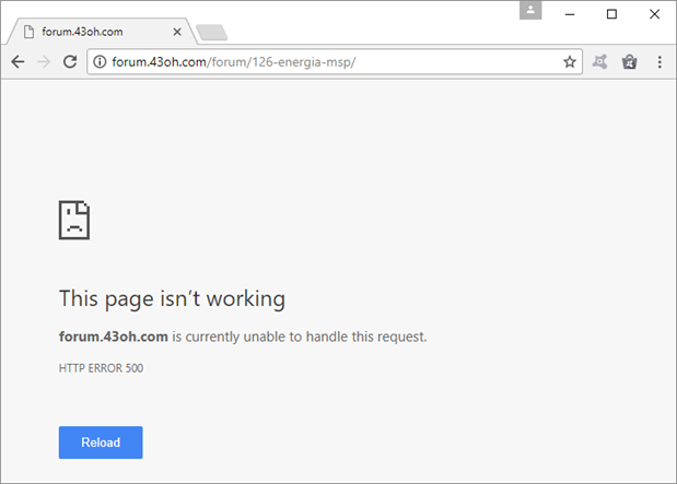
 

image


Sigh...

  • Sign in to reply

Top Comments

  • Jan Cumps
    Jan Cumps over 7 years ago +4
    Hey John, have you logged a post on 43Oh, ti e2e or here to get help for your problems? I usually get help there - also when there's an existing ticket with the same simptoms. people will tell you that…
  • rachaelp
    rachaelp over 7 years ago in reply to Jan Cumps +3
    Hi John, I second Jan's suggestion, it's probably worth posting up on all these forums to try and get help if you haven't already, as somebody will likely be able to point you in the right direction. It…
  • jkutzsch
    jkutzsch over 7 years ago in reply to jkutzsch +3
    One of the items I referred to quite a bit when planning this was dougw awesome table of pins from his blog 5 when he was explaining his pcb. Safe and Sound - Hazardous Gasses PCB - blog 5 I really found…
  • Jan Cumps
    Jan Cumps over 7 years ago in reply to jc2048

    The only thing he has to do (It took me some time to check this) is replace every occurrence in his code of Serial with Serial1.

    The Serial1 object reads and writes to P3.2 and P3.3


    If he reads or writes to Serial(), traffic is exchanged with the host PC

    If he reads or writes to Serial1() traffic goes to P3.2 and P3.3.

    Both can be used at the same time in the same sketch.

    • Cancel
    • Vote Up +2 Vote Down
    • Sign in to reply
    • More
    • Cancel
  • jc2048
    jc2048 over 7 years ago in reply to Jan Cumps

    Isn't it better for John to use the regular Boosterpack standard pins rather than breaking out the ones intended for the USB? It shouldn't take much to adapt any examples to work with UART2.

    • Cancel
    • Vote Up +1 Vote Down
    • Sign in to reply
    • More
    • Cancel
  • Jan Cumps
    Jan Cumps over 7 years ago in reply to jc2048

    I've put a reply in the blog # 10


    https://www.element14.com/community/community/design-challenges/texas-instruments-safe-sound-wearables-design-challenge/…


    The Serial isn't broken out to 3.2 and 3.3, but via the bridge jumpers in the middle of the board to the USB.

    • Cancel
    • Vote Up +2 Vote Down
    • Sign in to reply
    • More
    • Cancel
  • jc2048
    jc2048 over 7 years ago in reply to jc2048

    image


    I see what they've done [I cheated and read the documentation on their website]. The 'direct' mode bypasses the Arduino's processor (the circuit above is for the Arduino Uno) and sends the data directly to the PC via the USB. So it just looks like there are two TX outputs connected together; as long as the Arduino processor has its serial disabled, then it would work. And that's the reason for the switch on the GPS shield - if it wasn't there, you couldn't isolate the TX and you then wouldn't then be able to download sketches to the Arduino if the shield were attached [because the two TXs would collide].

    • Cancel
    • Vote Up +2 Vote Down
    • Sign in to reply
    • More
    • Cancel
  • jc2048
    jc2048 over 7 years ago in reply to jkutzsch

    "I can't remember off the top of my head..."


    Which is why you write everything down in a log book...


    If I were trying to get this to go, I'd use a scope to look at the serial coming out (but then, being a hardware engineer, I do all my debugging with a scope). If you don't have a scope, how about using what you do have? You've already had the Arduino receiving data, so why not wire up the Arduino AND the MSP432 at the same time? The Arduino can confirm that the NEMA messages are being transmitted and are there for the MSP board to read, and then you just need to fiddle around with the 432 software until you're reading them.


    Put the shield on the Uno, wire the TX from the Adafruit shield to the RX input on the TI board (P3.2) and link the GNDs together. Keep the connections short and, if you want to avoid the possibility of one powering the other through the signal connection when one has power and the other doesn't, include a resistor between the two [a 470 ohm resistor would limit the current to something that wouldn't do much harm whilst not affecting the signal too much].

    • Cancel
    • Vote Up +1 Vote Down
    • Sign in to reply
    • More
    • Cancel
>
element14 Community

element14 is the first online community specifically for engineers. Connect with your peers and get expert answers to your questions.

  • Members
  • Learn
  • Technologies
  • Challenges & Projects
  • Products
  • Store
  • About Us
  • Feedback & Support
  • FAQs
  • Terms of Use
  • Privacy Policy
  • Legal and Copyright Notices
  • Sitemap
  • Cookies

An Avnet Company © 2025 Premier Farnell Limited. All Rights Reserved.

Premier Farnell Ltd, registered in England and Wales (no 00876412), registered office: Farnell House, Forge Lane, Leeds LS12 2NE.

ICP 备案号 10220084.

Follow element14

  • X
  • Facebook
  • linkedin
  • YouTube