In this blog, I will show how all the electronics parts have been placed inside the case and connected to existing LEDs, push button and fan
Other posts in this serie
- ColdCase - Blog# 1 - Introduction
- ColdCase - Blog #2 - The refrigerated cell
- ColdCase - Blog #3 - Preparing the environment
- ColdCase - Blog #4 - The software
- ColdCase - Blog #5 - Final assembly
- ColdCase - Blog #6 - The Android app
- ColdCase - Blog #7 - Final assembly
1. The ATX connector
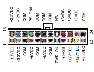
For the sake of reusing the ATX power supply, I desoldered the female connector from the motherboard. I soldered all the wiring required to the female connector, according to the following pinout
This is the connector with all the wirings
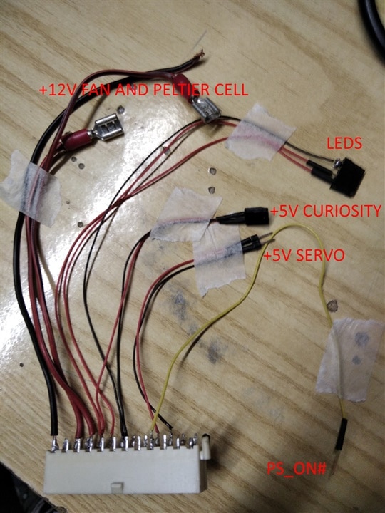
More details about the wiring:
- PS_ON# is driven low when we want to switch on the power supply
- +5 SERVO powers the Servo Click board. This is connected to the +5VDC, which is powered when the ATX power supply has been switched on by means of the PS_ON# pin
- +5V CURIOSITY power the Curiosity Nano board. Because this is connected to the +5VSB pin of the ATX connector (which is always powered), this means the Curiosity Nano is always on and can monitor the status of the push button on the front panel
- LEDS connector has a ground and two +5V from +5VSB pin and PWR_OK pin. The first LED, connected to +5VSB pin, shows whether the ATX power supply is connected to the mains. The second LED is connected to PWR_OK pin. According to the specification, the Power-Good signal as a +5-volt (V) signal generated in the power supply when it has passed its internal self-tests and the outputs have stabilized. This normally takes between 0.1 and 0.5 seconds after the power supply is switched on. The signal is then sent to the motherboard, where it is received by the processor timer chip that controls the reset line to the processor. However, this is not completely true in my case, because PWR_OK goes high only when a load is detected on the +12V power supply
- +12V is connected to the switches that controls the PC fan and the Peltier cell
2. The motherboard
All the electronic parts have been mounted on a 3D-printed frame
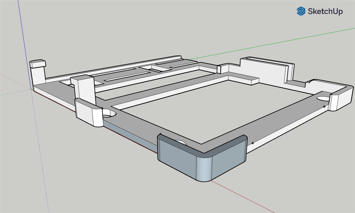
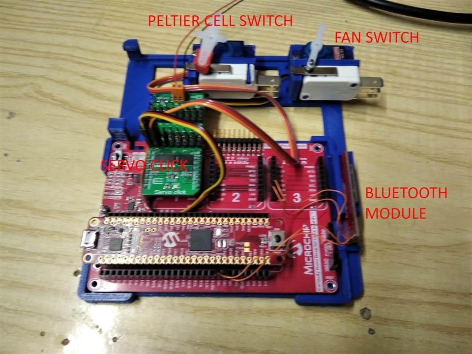
Here is the motherboard with most of the components already in place
3. The servo door
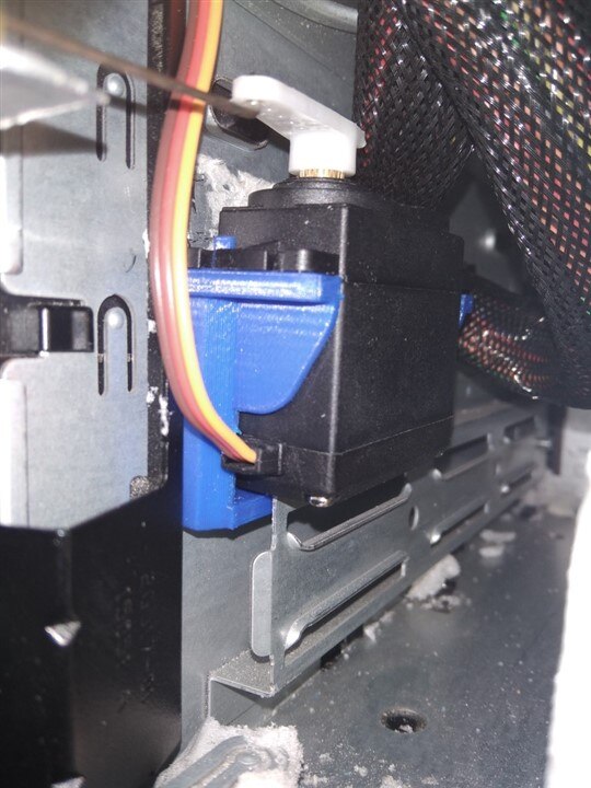
The front door is operated by a servo. The servo is housed in a 3D-printed bracket.
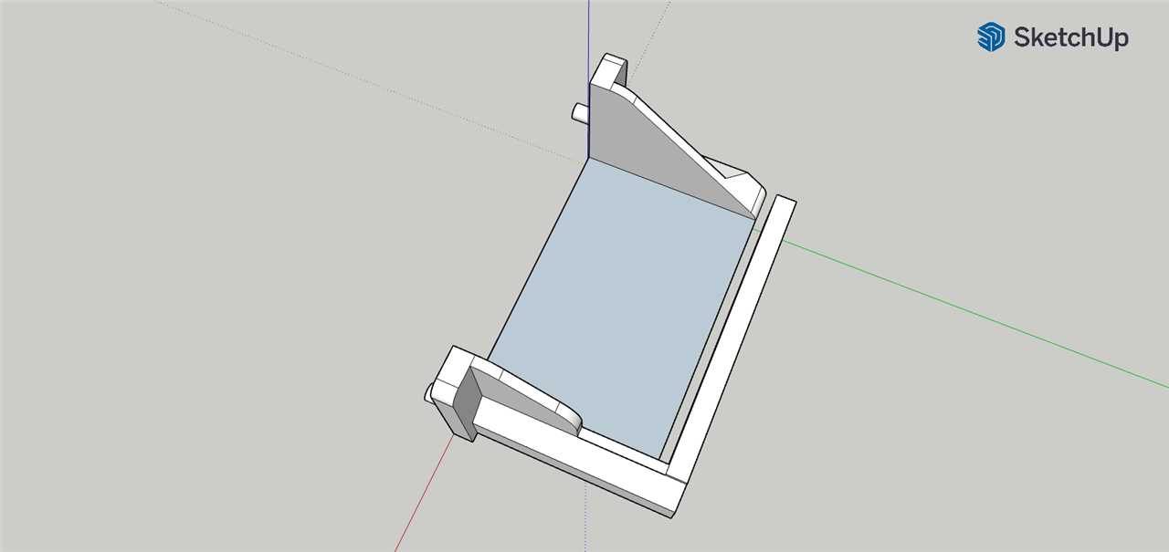
The clip on the bottom slides into a U-shaped frame in the frame
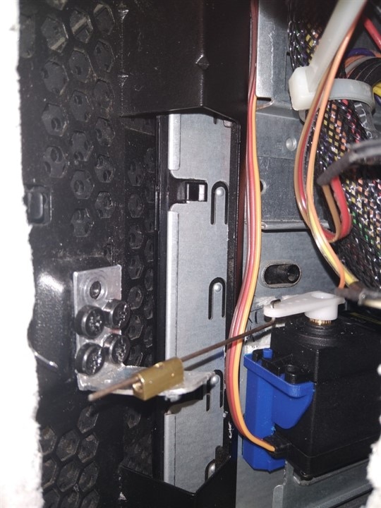
An aluminum bracket has been shaped to reused some existing screws.
4. Final assembly
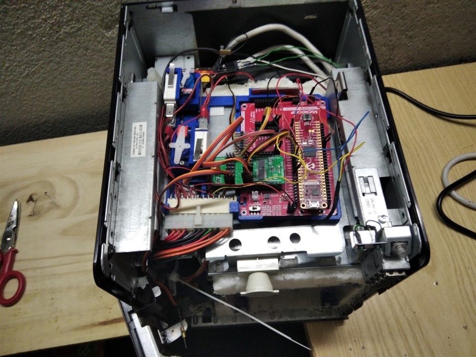
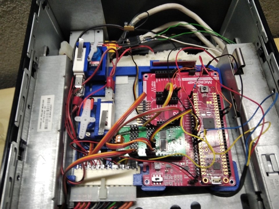
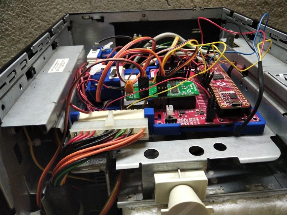
Here are some pictures with all the parts mounted in place

-

DAB
-
Cancel
-
Vote Up
0
Vote Down
-
-
Sign in to reply
-
More
-
Cancel
-

amgalbu
in reply to DAB
-
Cancel
-
Vote Up
0
Vote Down
-
-
Sign in to reply
-
More
-
Cancel
Comment-

amgalbu
in reply to DAB
-
Cancel
-
Vote Up
0
Vote Down
-
-
Sign in to reply
-
More
-
Cancel
Children