

Time to Build a Robot!
Throughout this Introduction to Robotics series, Miloš Rašić has gradually built the knowledge needed to design, build and control robotic systems. It began with the fundamentals of electronics, sensors, actuators, CAD and mechanical design in Building the Foundations of Your First Robot, before moving into closed-loop control, motion profiles and robotic software concepts in PID Control, Motion Profiles and ROS Explained. The previous instalment then applied many of those concepts to a complete robot arm in Building and Programming a SCARA Industrial Robot Arm.
For the fourth part of the series, the focus shifts to one of the most recognisable categories of robotics: the mobile robot.
Unlike a robot arm that operates from a fixed base, a mobile robot must move through its environment, react to what it senses, maintain control of its motion and attempt to understand where it is. Even the simplest mobile robot quickly introduces concepts such as locomotion, wheel odometry, sensor-driven behaviours and environmental mapping.
The platform Miloš develops combines many of the ideas explored throughout the series into a compact differential-drive robot built around a Raspberry Pi Pico 2 W, geared motors with integrated encoders, infrared cliff sensors, wireless communications and a custom firmware and GUI stack.
“This was for people that were making their first robot and just wanted to see something move.”
Rather than introducing advanced SLAM systems, sensor fusion stacks or computer vision pipelines, the project focuses on the core building blocks that underpin mobile robotics. The result is a platform that remains approachable while still exposing many of the same challenges encountered in larger autonomous systems.
Bringing the Previous Parts Together
This project is the fourth instalment of the series where every subsystem relies on concepts already introduced.
- Building the Foundations of Your First Robot - An Introduction to Robotics introduced the core hardware elements such as sensors, motors, microcontrollers, CAD design and manufacturing.
- PID Control, Motion Profiles and ROS Explained - An Introduction to Robotics explored feedback systems, control loops and software structures used to regulate motion.
- Building and Programming a SCARA Industrial Robot Arm – An Introduction to Robotics demonstrated how those ideas could be combined into a complete robotic system with embedded firmware and a graphical user interface.
In this mobile robot platform, all of those concepts return. Motors require drivers, sensors require interpretation, encoder feedback must be processed, software needs to communicate with hardware, and control loops keep the system stable. The key difference is that the robot is no longer bolted to a workbench. It must move through the world while attempting to keep track of its own position.
Locomotion: How Do Mobile Robots Move?
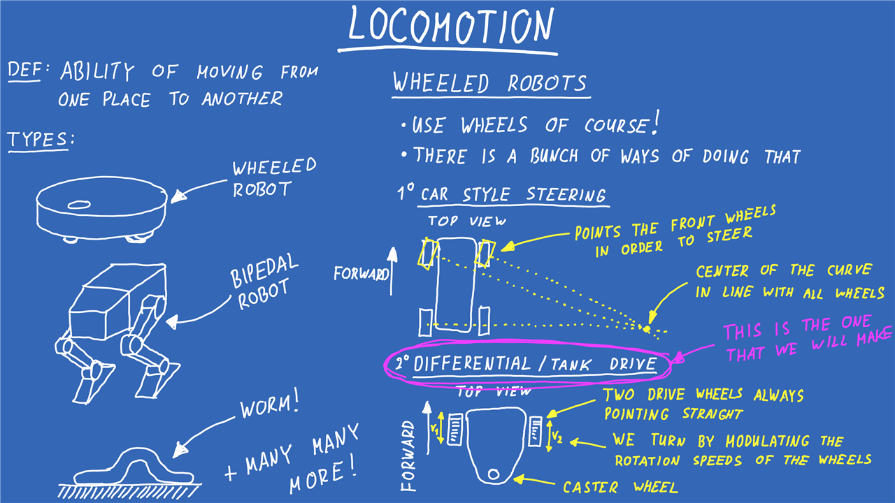
Miloš begins by introducing locomotion, the ability of a robot to move from one place to another.
“Locomotion is the ability of moving from one place to another. So in robotics it’s how does the robot move?”
Robots can move in many different ways. Wheeled robots, walking robots, tracked vehicles and bio-inspired machines all fall under the broad category of locomotion. Since the objective of this project is to introduce the fundamentals of mobile robotics without adding unnecessary complexity, Miloš focuses on wheeled robots.
Even then, there are multiple approaches. A car changes direction by altering the angle of its steering wheels. Some robots use tracks while others employ more specialised wheel arrangements such as mecanum wheels. For this platform, the chosen solution is differential drive.
“In this case the wheels are fixed, we can just play with their speed and direction.”
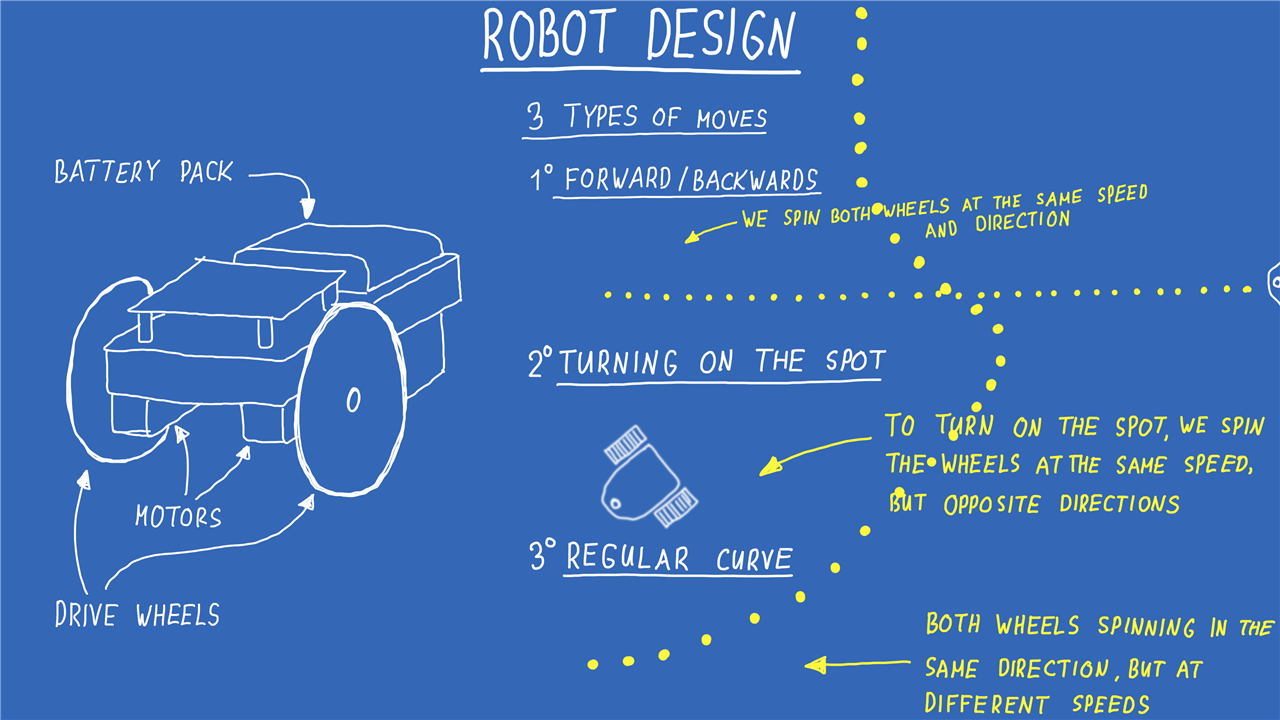
A differential-drive robot uses two powered drive wheels and a third passive support wheel, normally a caster. Steering is achieved entirely through the relative speed of the left and right wheels.
If both wheels rotate at the same speed, the robot travels in a straight line. If one wheel turns faster than the other, the robot follows a curve. If the wheels rotate in opposite directions, the robot can rotate on the spot.
The design keeps moving parts to a minimum while still demonstrating many important mobile robotics concepts.
“The vacuum robot is the prime example of a differential drive robot.”
That comparison is particularly fitting because robot vacuum cleaners use many of the same underlying principles explored in this project: differential drive, wheel feedback, environmental sensing and autonomous movement.
Selecting the Hardware
With the robot architecture decided, the next step was selecting the hardware.
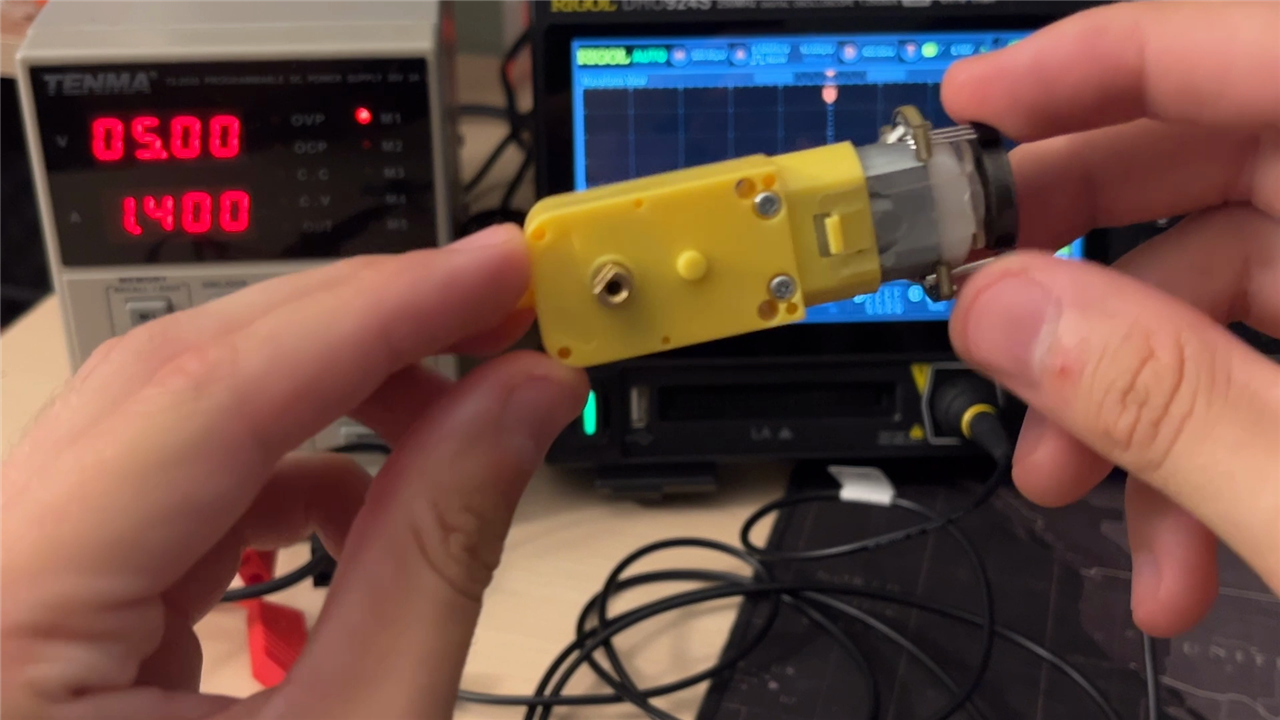
The drive system is built around two DFROBOT geared DC motors with integrated encoders. The gearbox reduces the motor speed to something useful for driving a robot, while the encoder provides rotational feedback.
These encoders are important because they allow the robot to measure wheel speed and estimate wheel position. Without them, the firmware could only command a motor and hope it behaved as expected. With encoder feedback, movement can be measured, controlled and visualised.
“This here is an encoder.”
For anyone unfamiliar with encoders and feedback systems, the element14 Learning Center article Magnetic Encoders provides useful background on how rotational position and velocity can be measured electronically.
The motors are controlled through a DFROBOT dual motor driver. The microcontroller generates a direction signal and a PWM signal for each motor, while the motor driver handles the current required by the motors themselves.
// Wiring to the DRI0044 (TB6612FNG) breakout:
//      PICO           DRI0044
//      PIN_M?_PWM --> PWM1 / PWM2   (speed,     0..100% duty)
//      PIN_M?_DIR --> DIR1 / DIR2   (direction, LOW/HIGH)
//      3V3        --> VCC           (logic supply)
//      battery    --> VM            (motor supply)
While deceptively simple, this arrangement introduces readers to one of the most common motor-control structures used throughout robotics.
Those wanting a deeper understanding of motor drive electronics can explore Motor Control: Motor Drive Control for Makers, which covers PWM, motor drivers and motor control fundamentals in more detail.
The Raspberry Pi Pico 2 W and Power System
To coordinate the robot's sensors, motors and communications, Miloš selected a Raspberry Pi Pico 2 W.
“Why? Because it’s a really cheap and rather powerful microcontroller and it also has Wi-Fi and Bluetooth so we can easily control it wirelessly.”
The Pico handles the embedded side of the project. It reads sensor data, processes encoder counts, executes the PID control loops, communicates with the GUI and generates motor commands.
This is another point where concepts from earlier parts of the series return. The microcontroller acts as the bridge between the electronic hardware and the software logic driving the robot's behaviour.
An interesting challenge emerged from the encoder hardware. The motor encoders operate using 5 V logic, while the Pico uses 3.3 V logic.
“The encoders on these motors are 5V logic and our microcontroller here is 3.3V logic so we also need a level translator.”
A simple level-shifting circuit is therefore required between the encoder outputs and the microcontroller inputs. This kind of practical electrical consideration appears frequently in real robotics projects and is often overlooked when looking only at block diagrams.
The robot itself is powered from a four-cell AA battery pack, supplying approximately 6 V for the motors and supporting circuitry. A regulator generates the required logic voltage for the Pico and sensors.
Miloš jokingly highlights another very real robotics issue: battery quality.
If the supply voltage drops too far under load, motors may continue turning while the microcontroller resets unexpectedly, producing brownouts and unpredictable behaviour.
Power distribution often receives less attention than software or mechanics, but it has a huge influence on reliability. Readers interested in that topic may find Power Essentials for Makers useful supplementary reading.
Cliff Detection Instead of Obstacle Detection
Many consumer robots rely on bump sensors, cameras or LiDAR to detect obstacles. Rather than attempting to build a complete navigation system, Miloš deliberately simplifies the sensing challenge.
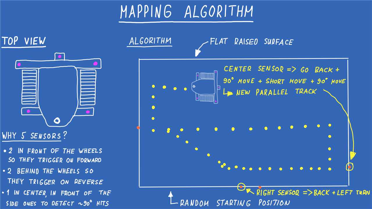
The robot uses five downward-facing infrared sensors as cliff detectors.
“Instead of detecting walls we will detect cliffs.”
This changes the problem from obstacle avoidance to edge detection. Rather than navigating around furniture, the robot explores a raised surface and attempts to identify where the surface ends.
The approach is particularly useful for demonstrating how sensor information can directly drive robotic behaviour without requiring complex perception systems.
The firmware includes logic specifically designed around this sensor arrangement.
// On a downward-facing cliff sensor a set bit means
// "this sensor SEES THE FLOOR".
// Danger is the absence of floor.

#define IR_CLIFFS(mask) ((uint8_t)((~(mask)) & IR_ALL_BITS))
The accompanying comment in the firmware highlights a surprisingly common mistake.
// Getting that backwards is not a cosmetic bug:
// it produces a robot that refuses to move on solid
// ground and drives happily over a cliff.
It is exactly the kind of observation that comes from testing on physical hardware rather than simulation.
Designing the Chassis
With the electronics established, attention shifted towards the mechanical design.
Miloš created the platform in Fusion 360 and structured it around a simple differential-drive layout consisting of two powered wheels and a caster.
“We’re going to drop into Fusion 360, do some CAD design.”
The project is intentionally straightforward so that readers can recreate it even if they do not have access to the exact same fabrication tools.
While the published design uses 3D-printed components, the robot could be built from much simpler materials. The important requirement is maintaining alignment between the drive wheels.
If the wheels are not parallel, the robot will naturally drift and produce misleading results during testing.
That lesson mirrors many industrial robotics projects: elegant software cannot compensate indefinitely for poor mechanical fundamentals.
Firmware, Communications and Software Architecture
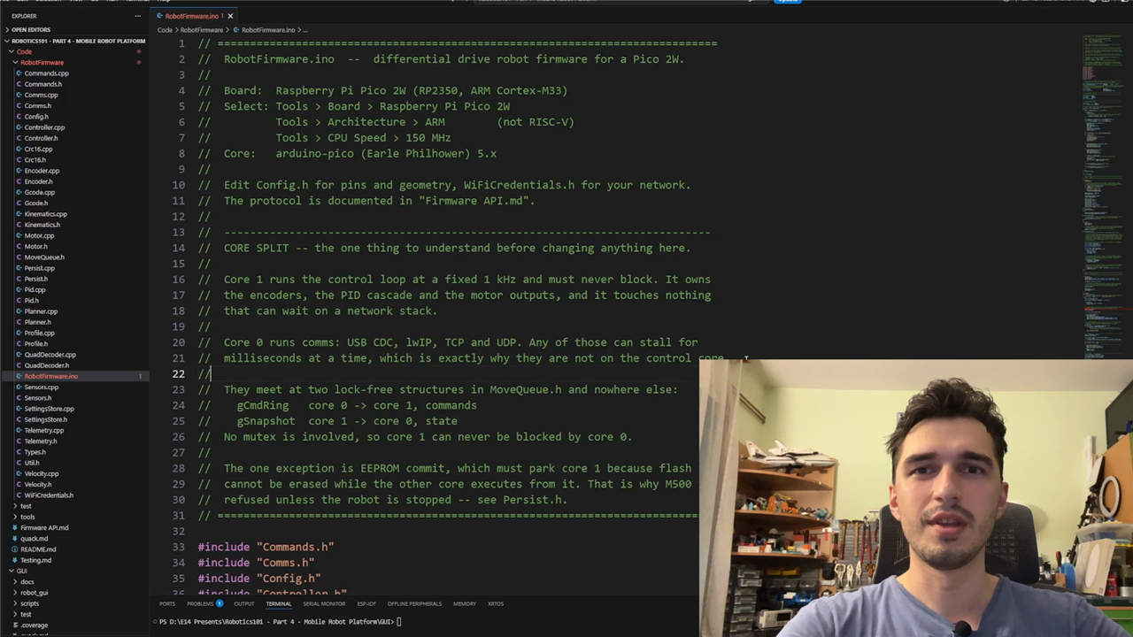
The software is split into two major pieces. The first is embedded firmware running on the Pico. The second is a desktop GUI used for control, monitoring and tuning.
Readers who followed the SCARA robot arm build will recognise a very similar development workflow. Once again, Miloš combines embedded software and a graphical control environment into a single ecosystem.
The firmware is deliberately modular.
// Everything the host can ask for goes through here,
// so Serial and WiFi are guaranteed to behave identically.
This ensures that commands behave the same whether they are sent through USB Serial or over Wi-Fi.
The firmware also uses movement concepts familiar to anyone who has worked with CNC machines or 3D printers.
// Modal state (G90/G91, the last F,
// the programmed wheel target) lives here
// rather than in the controller.
The resulting system is flexible enough for interactive testing while remaining structured enough for more advanced automation later on.
Applying PID Control to a Real Robot
The theory behind PID control was explored previously in PID Control, Motion Profiles and ROS Explained. Rather than revisiting the mathematics, this project demonstrates how those concepts are applied to a mobile robot.
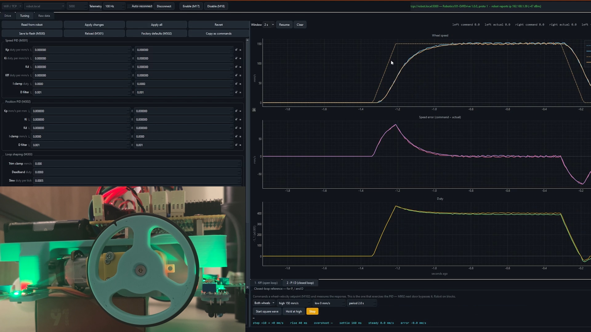
Each wheel uses encoder feedback to regulate speed through a closed-loop controller.
// SPEED loop (inner): error in mm/s -> output in duty

#define SPD_KP 0.0015f
#define SPD_KI 0.0080f
The GUI exposes tuning controls, making it possible to observe how the robot responds as controller values change.
Miloš demonstrates the practical tuning process by examining how quickly the wheel reaches its target speed. A response that is too slow typically indicates insufficient proportional gain. Increasing Kp improves responsiveness, but pushing it too far can create oscillation and instability.
Those behaviours become immediately visible when real motors, gearboxes, batteries and sensors enter the equation. The project therefore serves as a practical continuation of the PID concepts introduced earlier in the series, showing what they look like when attached to a physical robot rather than a simplified example. One of the biggest conceptual differences between this project and the earlier SCARA robot arm is localisation. A robot arm operates from a known position. Its joints move relative to a fixed base and its location in the world remains constant.
A mobile robot is different. Once it begins moving, it has to estimate where it is. This project deliberately avoids advanced localisation systems such as visual SLAM or sensor fusion. Instead, the platform introduces a simpler concept: wheel odometry.
By measuring wheel rotation using encoders, the robot can estimate how far it has travelled and build a rough picture of its movement.
“We are only here calculating where it is based on the encoder positions.”
While not perfectly accurate, odometry provides a powerful introduction to localisation and forms the basis of countless robotics systems.
Creating a Simple Mapping Behaviour
Once the platform could drive reliably and the sensors were functioning correctly, it was time to make the robot perform a task.
The chosen exercise was mapping the edge of a raised surface.
The mapping algorithm intentionally remains simple. Whenever a cliff sensor detects an edge, the robot reverses and changes direction. If the centre sensor detects a head-on edge, the robot performs a more substantial manoeuvre before continuing.
“As we detect a certain edge we’re gonna go back, turn around, something similar that your robot vacuum is doing.”
This behaviour is significant because it combines every major subsystem.
- The mechanical design determines how the robot moves.
- The motors execute the movement.
- The encoders provide feedback.
- The PID loops regulate motion.
- The sensors detect the environment.
- The algorithm determines how the robot reacts.
The GUI then visualises the results.
As the robot continues exploring, the triggered cliff detections begin forming a representation of the table edge.
“It’s forming a rather nice point cloud around the edges of the table.”
The robot is not creating a complete map in the modern SLAM sense, but it does demonstrate how movement and sensing can be combined to generate useful environmental information.
What Beginners Should Focus On and Further Learning on element14 Community
One of the most useful aspects of this project is that it intentionally avoids overwhelming complexity.
Rather than introducing every possible robotics concept at once, Miloš focuses on a small number of ideas and demonstrates how they fit together.
- Differential-drive locomotion.
- Motor control and motor drivers.
- Wheel encoders.
- PID speed regulation.
- Microcontroller-based firmware.
- Infrared sensing.
- Wireless communications.
- Simple mapping behaviour.
- Basic odometry.
Along the way, readers also see the less glamorous aspects of robot development: wiring issues, logic-level compatibility, battery behaviour, sensor interpretation, wheel alignment and controller tuning. Those are often the challenges that consume the most development time on real projects. Readers wanting to explore the wider Introduction to Robotics series and related topics can continue with:
- Building the Foundations of Your First Robot
- PID Control, Motion Profiles and ROS Explained
- Building and Programming a SCARA Industrial Robot Arm
- Designing a Mobile Robot Platform with Inverse Kinematics and Wireless Control
- element14 Learning Center
- Power Essentials for Makers
- Motor Control: Motor Drive Control for Makers
- The Basics of Microcontrollers
- Magnetic Encoders
- An Introduction to Programming with Python
- Essentials of Robot Operating System 2
- Jeremy Blum Arduino Tutorials
Final Thoughts
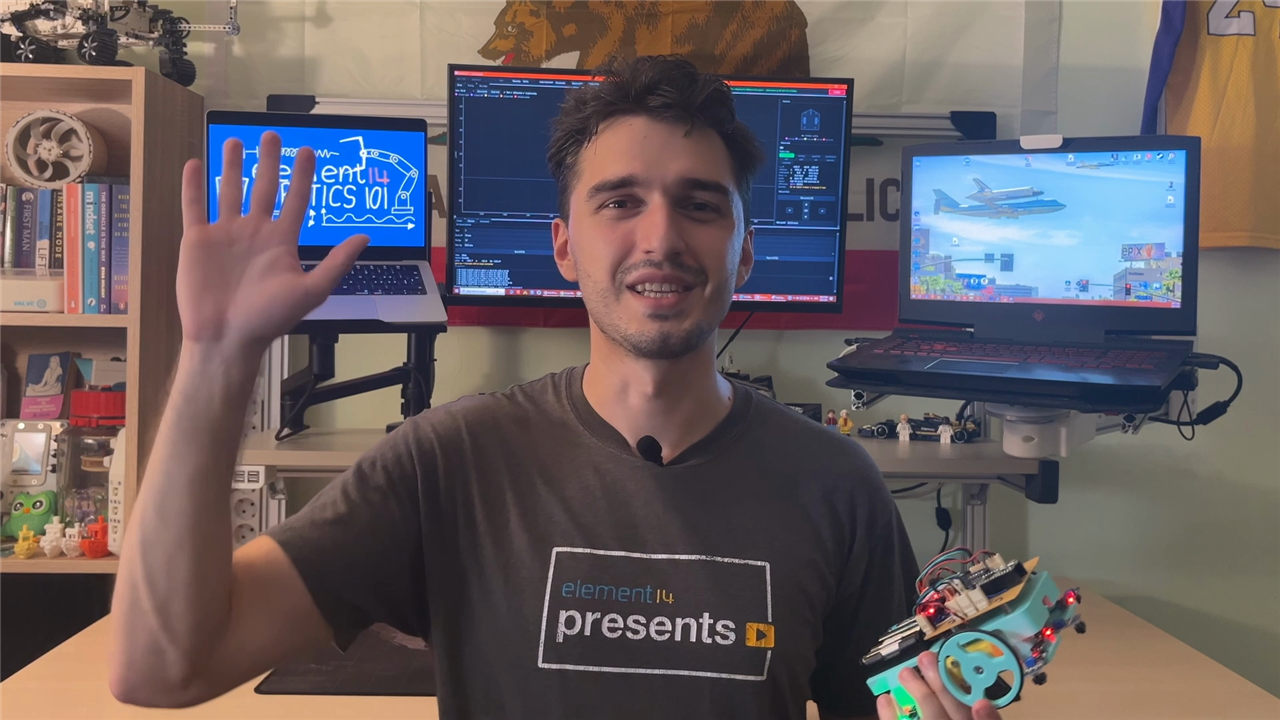
As the fourth instalment of the Introduction to Robotics series, this project acts as a bridge between foundational robotics theory and the challenges of mobile robotics.
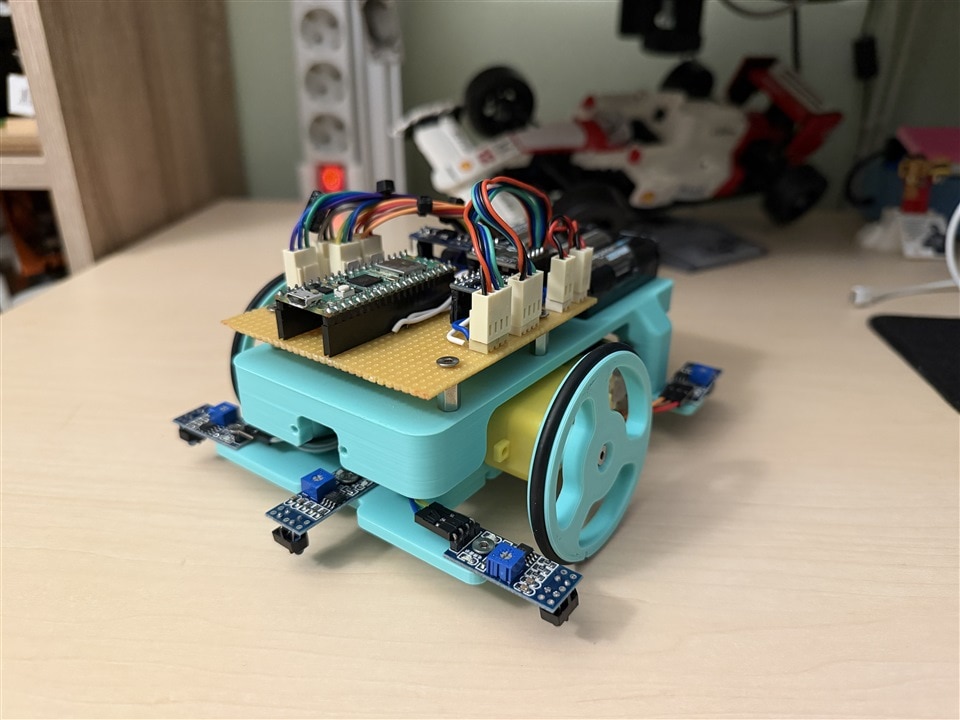
The robot combines electronics, mechanical design, feedback control, embedded software and environmental sensing into a platform that is simple enough to understand yet capable enough to demonstrate genuine robotics concepts.
By the end of the project, the robot can drive, regulate its wheel speed, detect table edges, estimate its movement, visualise sensor data and build a rough representation of its surroundings.
Those capabilities may appear straightforward, but together they form the basis of a huge number of robotic systems.
“I would love to explore more complex robotics projects with you.”
Whether the next step is odometry improvements, more advanced mapping, ROS integration, navigation algorithms, sensor fusion or entirely new robot architectures, this platform provides a practical foundation on which those future topics can be built.
Supporting Files and Links
Bill of Materials / Parts Used
| Product Name | Manufacturer | Quantity | Buy Kit |
|---|---|---|---|
| DFROBOT Motor | DFROBOT | 2 | Buy Now |
| DFROBOT Motor Driver | DFROBOT | 1 | Buy Now |
| Raspberry Pi Pico 2W | RASPBERRY PI | 1 | Buy Now |
| IR Sensor | SEEED STUDIO | 5 | Buy Now |
| Wheel | DFROBOT | 2 | Buy Now |
Additional Parts
| Product Name | Manufacturer | Quantity |
|---|---|---|
| AA battery holder | 4 | |
| M3 machine screws | ||
| Small caster wheel | ||
| AA batteries | 4 | |
| Perfboard and wires |

