


Previous blogs for this project as prerequisites:
Prototyping with FPGAs - Part 1 - Basics
Prototyping with FPGAs - Part 2 - Combinational Logic with Xilinx ISE on Spartan 6 FPGA
Prototyping with FPGAs - Part 3 - Sequential Logic with Quartus Prime on Cyclone-IV FPGA
Things used in this project:
Hardware:
| S. No | Component | Qty |
|---|---|---|
| 1 | DE0-Nano FPGA Development Board - Terasic Technologies - Buy | 1 |
| 2 | 360-Degree Rotary Encoder with Push Switch - Buy | 1 |
| 3 | Digilent Pmod VGA: Video Graphics Array - 12-bit - Buy | 1 |
| 4 | Jumper Cables (Female to Female) | 1 |
| 5 | VGA Cable and Monitor | 1 |


Software:
Intel Quartus Prime Software Lite Edition - v16.1 - Download
Idea:
This project aims to build a simple Pong game (single player) by applying all the concepts learned in the previous sections of this blog.
The input (user control) for the pong game will be via the Rotary Encoder and the output can be seen in the VGA Monitor.
Concepts:
1. Rotary Encoder:-
This is the internal wiring of a rotary encoder. The yellow color signifies VCC and the grey signifies GND. When the encoder is rotated the two outputs toggles between 1 and 0.

Based on the position of the pulses, we can determine the direction and we can take the number of pulses as count in that direction.

Let the blue waveform be output 1 and green be output 2.
So how can we determine the direction? If you look very closely at the waveform, you will notice that at every rising edge of output 1, if output 2 is LOW, then it's clockwise.
At the rising edge of output 1, if output 2 is HIGH, then we can say it's counterclockwise but this method cannot be reliable to decode signals in real life.
How do we decode the signals?
Answer - A quadrature decoder. Do check out the post The Logical Project by dougw on Quadrature decoder for more info!
Design of quadrature decoder:

Testing the design:
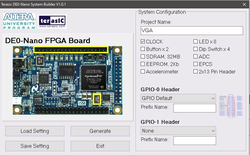
We will be using the Terasic System Builder to build the project for Quartus Prime.
| {gallery} TSB |
|---|
Select Clock, LEDs, and GPIO Header 1 |
Save it in the project folder. |


We shall use the 8 onboard LEDs as the output to the counter and one RGB led for the direction of the rotary encoder and to check the switch of the rotary encoder.
You can make yourself familiar with Quartus Prime software by looking at Part 3 of this blog series.
Verilog Code:

QSF File and SDC File:


The output of the quadrature decoder:
2. VGA - Video Graphics Array:
Well, this term should be very familiar to you as we might have used a VGA Monitor at least once or might be using it even now.
first introduced with the IBM PS/2 line of computers in 1987 after which it was widely used in almost all PCs with DVI until the arrival of HDMI in 2003 after which it was widely adopted due to higher resolution and better frame rates, by the year 2015 over 4 billion devices use HDMI.
Let's take a look at the VGA Pinout:

There are 5 main signals in VGA, they are Red, Green, Blue, Horizontal Sync, and Vertical Sync.
A useful piece of information from the University of Toronto:
"A VGA Monitor can be thought of as a grid of pixels where each pixel is a picture elements that can be set to a specific color. There are 480 rows and each row consists of 640 pixels. (used in this project) The VGA interface works serially, that is, color information for each respective pixels is sent one after the other, as opposed to all at once.
Colors can be represented using a triplet consisting of the intensities of each fundamental color (Red, Green, Blue). The monitor expects these values to be analog, and thus a DAC (Digital to Analog Converter) is used.
An important fact to realize is that the VGA monitor does not have memory and thus will not store the pixel information being written to it. Instead, the pixels must be continuously sent to the display to achieve a stable image. The VGA Adapter does have memory and will be responsible for constantly sending out the pixel information."
Let's take a look at the timing diagram to understand more about the protocol:


Testing the VGA protocol:
| {gallery} VGA |
|---|
Select the clock and GPIO header |
Save it in the right location |

I will be using a Verilog module to generate the horizontal sync and vertical sync for the VGA

Now once we have this module we can draw any shape on the monitor.

The clock required is 25MHz, thus first the onboard 50MHz is divided by 2 to get 25MHz.
The hvsync_generator module will be instantiated in the VGA (top) module. The numbers 160, 240 indicate horizontal positions in the monitor, and 480 is the maximum vertical distance possible in the monitor.
R-1, G-1, B-1 corresponds to white color, R-1, G-0, B-0 corresponds to red color, R-1, G-1, B-0 corresponds to Yellow color, and so on.
Constraints file and SDC file:


Output:
Now that we have learned and tested the rotary encoder and the VGA module, let's start building the pong game.
Making of the Pong Game:
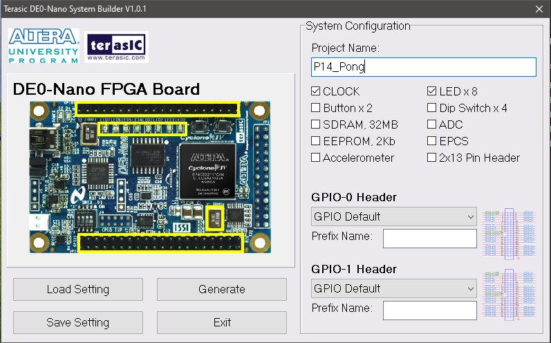
| {gallery} Pong |
|---|
Give your project a name and select LEDs, and the 2 GPIO headers |
Save it in the project folder |
Open the QPF File from Quartus prime |
Make sure all files are added to the project, if not add them manually. |


1. First create a file for the generation of horizontal sync and vertical sync signals and fixing the display area

2. Next add the code for the pong game as explained in the following steps
Declare the inputs and outputs then the frequency divider as discussed in Part 3 of the blog series

3. Next instantiate the module for horizontal sync and vertical sync signals and write the code for the rotary encoder as explained previously in this blog.
Then we move the bouncer according to the counter value which can be incremented or decremented by the rotary encoder

4. In this step let us write the code for the ball which will be used in the pong game:

5. Based on the slide switches, select if the bouncer has to move manually or automatically, and based on the position of the ball, reverse the direction of the ball collides with any object.
To observe the collisions and the direction of the rotary encoder rotations set that output to the onboard LEDs

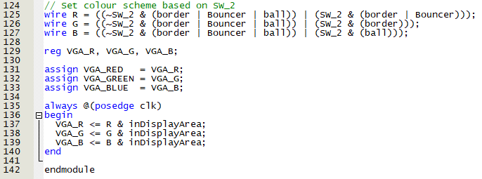
6. Next write the code to update the position of the ball each time it collides and the collision detectors are reset

7. Finally change the colors based on the switch positions and assign the RGB signals to the respective outputs and display only if it's within the monitor's total area.
8. Now write the constraints file and the SDC file
Constraints file:


SDC File:

Synthesized Logic Diagram:
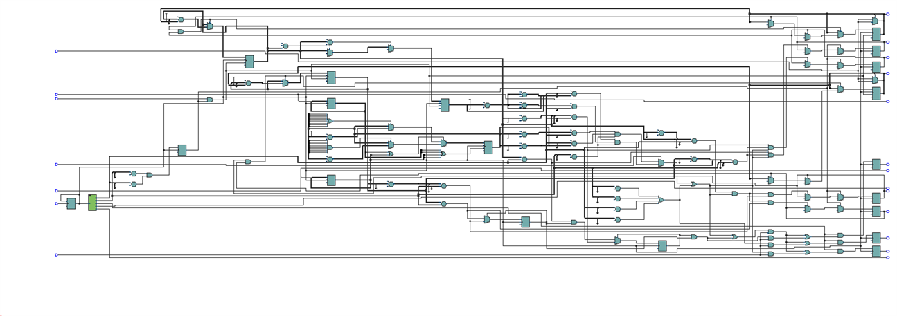
It's too complex to analyze, but it does work!
Connections:
Take a look at the constraints and the images given below to get more idea on how to connect the modules.


VGA:
In the Pmod VGA, you will notice that it is capable of 12-bit but in this project, we use only 3-bits one for Red, one for Green, and one for Blue.
Connect the Red pin of DE0 Nano to R3 of Pmod which has the highest weight in the DAC rest other bits will be grounded internally in Pmod.
The same way connect Green to G3 and Blue to B3. Horizontal Sync to HS and Vertical Sync to VS in Pmod. Connect the VCC and GND of the Pmod to the respective pins in the DE0 Nano.
Rotary Encoder:
Connect the Data Pin of the rotary encoder to the ROT_A and Clk Pin of the rotary encoder to ROT_B inputs as specified in the constraints file.
Connect the VCC and GND of the rotary encoder to the respective pins in DE0 Nano.
You're done!
Program the FPGA and give the connections (refer to the manual for pin-out) and you will see the ball and slider. Make sure you enable the required switches to see the operation.
Output:
Source Code for all 5 parts of the blog series:
Click here.
References:
1. https://how2electronics.com/construction-working-rotary-encoder/
2. https://reference.digilentinc.com/reference/pmod/pmodvga/reference-manual
3. https://reference.digilentinc.com/learn/programmable-logic/tutorials/vga-display-congroller/start
5. https://numato.com/kb/simple-vga-design-example-for-telesto/
I sincerely thank https://www.fpga4fun.com/. most of the code used in this project is borrowed from there and modified to the requirements.
Acknowledgments:
I thank rscasny sir for selecting me as a road tester for the USB104 A7: Artix-7 FPGA Development Board (used in Part 4 of this blog series) which gave me a lot of experience in FPGAs.
Last but not least I thank tariq.ahmad sir for sending me the DE0 Nano Development board and the Pmod VGA which was my prize for the Recycle & Retrofit Project14 contest.
Top Comments