element14 Community
element14 Community
    Register Log In
  • Site
  • Search
  • Log In Register
  • About Us
  • Community Hub
    Community Hub
    • What's New on element14
    • Feedback and Support
    • Benefits of Membership
    • Personal Blogs
    • Members Area
    • Achievement Levels
  • Learn
    Learn
    • Ask an Expert
    • eBooks
    • element14 presents
    • Learning Center
    • Tech Spotlight
    • STEM Academy
    • Webinars, Training and Events
    • Learning Groups
  • Technologies
    Technologies
    • 3D Printing
    • FPGA
    • Industrial Automation
    • Internet of Things
    • Power & Energy
    • Sensors
    • Technology Groups
  • Challenges & Projects
    Challenges & Projects
    • Design Challenges
    • element14 presents Projects
    • Project14
    • Arduino Projects
    • Raspberry Pi Projects
    • Project Groups
  • Products
    Products
    • Arduino
    • Avnet Boards Community
    • Dev Tools
    • Manufacturers
    • Multicomp Pro
    • Product Groups
    • Raspberry Pi
    • RoadTests & Reviews
  • Store
    Store
    • Visit Your Store
    • Choose another store...
      • Europe
      •  Austria (German)
      •  Belgium (Dutch, French)
      •  Bulgaria (Bulgarian)
      •  Czech Republic (Czech)
      •  Denmark (Danish)
      •  Estonia (Estonian)
      •  Finland (Finnish)
      •  France (French)
      •  Germany (German)
      •  Hungary (Hungarian)
      •  Ireland
      •  Israel
      •  Italy (Italian)
      •  Latvia (Latvian)
      •  
      •  Lithuania (Lithuanian)
      •  Netherlands (Dutch)
      •  Norway (Norwegian)
      •  Poland (Polish)
      •  Portugal (Portuguese)
      •  Romania (Romanian)
      •  Russia (Russian)
      •  Slovakia (Slovak)
      •  Slovenia (Slovenian)
      •  Spain (Spanish)
      •  Sweden (Swedish)
      •  Switzerland(German, French)
      •  Turkey (Turkish)
      •  United Kingdom
      • Asia Pacific
      •  Australia
      •  China
      •  Hong Kong
      •  India
      •  Korea (Korean)
      •  Malaysia
      •  New Zealand
      •  Philippines
      •  Singapore
      •  Taiwan
      •  Thailand (Thai)
      • Americas
      •  Brazil (Portuguese)
      •  Canada
      •  Mexico (Spanish)
      •  United States
      Can't find the country/region you're looking for? Visit our export site or find a local distributor.
  • Translate
  • Profile
  • Settings
Arduino
  • Products
  • More
Arduino
Arduino Forum Learning about H-bridges and transistors
  • Blog
  • Forum
  • Documents
  • Quiz
  • Events
  • Polls
  • Files
  • Members
  • Mentions
  • Sub-Groups
  • Tags
  • More
  • Cancel
  • New
Join Arduino to participate - click to join for free!
Actions
  • Share
  • More
  • Cancel
Forum Thread Details
  • State Verified Answer
  • Replies 38 replies
  • Answers 8 answers
  • Subscribers 397 subscribers
  • Views 2971 views
  • Users 0 members are here
  • frontpage
  • h-bridge
  • transistors
Related

Learning about H-bridges and transistors

ovidiub13
ovidiub13 over 9 years ago

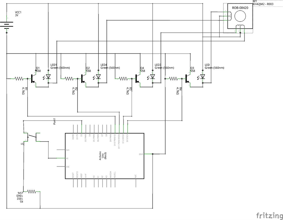
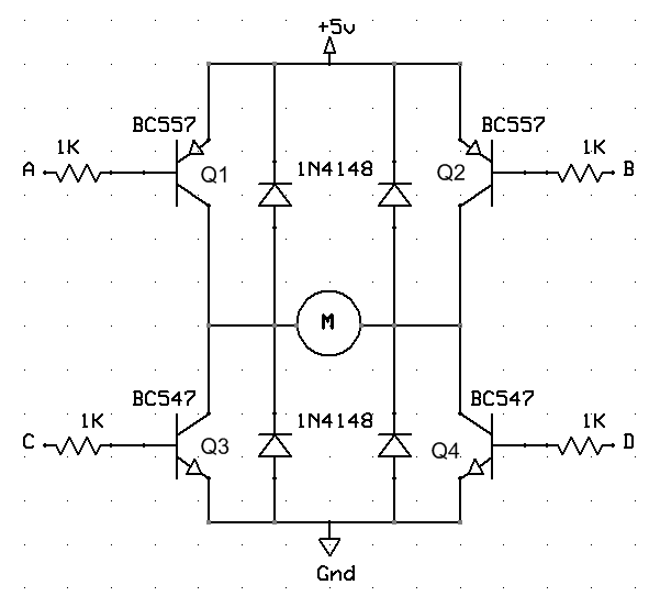
I'm trying to learn about transistors and H bridges towards a final goal of controlling a bipolar stepper motor with Arduino.


I've done the following half H-bridge in the process of learning:

image

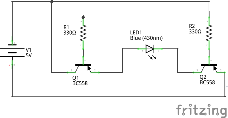
My first question: Why can't I use a single resistor to connect the base of both transistors to ground?

  • Sign in to reply
  • Cancel

Top Replies

  • strb
    strb over 9 years ago +1 suggested
    I'm not sure that this schematic works... the led isn't reverse polarized? Anyway use a pnp as pullup transistor and a npn as pulldown, it's a good thing to put also a limiter resistor to control the current…
  • strb
    strb over 9 years ago in reply to clem57 +1
    Great "how link" clem57
  • mcb1
    mcb1 over 9 years ago in reply to ovidiub13 +1 suggested
    What I'm having issues understanding is how transistors work You can consider a transistor as a switch (in this case they are either ON or OFF) The control part of the switch is the base to emitter (NPN…
  • Problemchild
    0 Problemchild over 9 years ago

    If you have a practical purpose for the stepper when you are done try the A4988 controllers you can get cheaply that work with the Arduino and have very good current handling etc


    http://www.ebay.co.uk/sch/i.html?_from=R40&_trksid=m570.l1313&_nkw=A4988&_sacat=0

    • Cancel
    • Vote Up 0 Vote Down
    • Sign in to reply
    • Verify Answer
    • Cancel
  • shabaz
    0 shabaz over 9 years ago in reply to Problemchild

    Even MagPi's article a couple of years ago got it wrong, they've subsequently revised their schematic in the PDF, but the thread that originally discussed it is here:

    The MagPi Magazine - Aimed at learners - Printed edition Kickstarter

    Quite a lot of hobbyists think its fine to stick 4 identical BJTs together and they'll have a H-bridge and save the costs of an IC.. forgetting that the IC actually works.

    • Cancel
    • Vote Up +1 Vote Down
    • Sign in to reply
    • Verify Answer
    • Cancel
  • Problemchild
    0 Problemchild over 9 years ago in reply to shabaz

    Yes except they are rarely identical unless you are limiting the gain with resistors  and the switching logic and drive for the bridge is often not considered so you end up with a system that can short out or not have enough gain to turn on properly or have too low voltage to do the same.


    Failing that just dealing with back EMFs etc is just an annoyance. Beyond proving you can do it you are better off with the chip unless you are switching mega-amps or something image

    • Cancel
    • Vote Up 0 Vote Down
    • Sign in to reply
    • Verify Answer
    • Reject Answer
    • Cancel
  • Problemchild
    0 Problemchild over 9 years ago in reply to shabaz

    That said he should be commended for trying the circuit out with "real" components first, much as I said that those70's -80's books I! bought were interesting for demonstrating concepts  with real components rather than just using an Arduino thingy mabob shield to do it all

    • Cancel
    • Vote Up 0 Vote Down
    • Sign in to reply
    • Verify Answer
    • Cancel
  • not2xs
    0 not2xs over 9 years ago in reply to ovidiub13

    If you want to get on to efficiently and reliably driving the stepper motor then as others have said a chip will be easiest; otherwise you will need to do everything the chip designer did. If you want to learn about H-bridges, the links supplied by mcb1 and Clem show good explanations. If you want to understand how transistors work, here is a quick but somewhat thorough description:


    The base to emitter connection works just like a semiconductor diode. Perhaps easiest to think of it as a variable resistor where the resistance changes with the voltage. Like a diode, if you try to drive it "backwards" it behaves like a near infinite resistance, and near no current flows. If you try to drive it "forwards", like a semiconductor diode if the voltage is less than about a half a volt it still behaves like a near infinite resistance, but somewhere a bit above that voltage the resistance starts to drop, until by around 0.7V (for silicon devices) the resistance is very low, nearing zero-ohms (except for that 0.7V lurking inside). The exact voltage between base and emitter where this happens will vary, mostly with temperature. That is why you typically connect an external resistor to the base, to control how much current flows there, otherwise the transistor will allow more than it can handle.


    The next thing to know about a transistor is it has a parameter (properly specified as h-subscript-fe if your fonts will allow that) I will abbreviate as h-fe here. This is the ratio of how much current will flow in the collector relative to how much in the base, if the rest of the circuit will allow it. Typically the h-fe will be somewhere around 1000 to 100000, and it will vary wildly with temperature and from individual transistor to transistor (even if they have the same part number). This means that the current in the collector will be 1000 to 100000 times the amount of current in the base - IF THE REST OF THE CIRCUIT WILL ALLOW IT. The current in the transistor's emitter is the sum of the current in the base and collector. However, when using transistors as switches, you usually want to drive them into "saturation". This is where the circuit cannot manage the collector to base current ratio and the collector to emitter voltage goes really low (below half a volt) while the transistor is trying really hard. With very low collector to emitter voltage, not much power gets consumed inside the transistor meaning it does not get as hot and more power is available to go into the load.


    There are two common configurations for connecting up a transistor, and you have both in your circuit above. One frequently used way is called "common emitter", here the emitter is wired to some known voltage, the base is wired to have some current flow into it (or not) while considering that 0.7V drop, and the "load" is connected to the collector where a higher amount of current is switched. Another common way is called "emitter follower", where the base is driven to a known voltage, the "load" is connected to the emitter, and the emitter will stay around 0.7V away from the base voltage with any needed extra current to achieve that coming through the collector. To get an emitter-follower into saturation, the base will need to be driven to a voltage beyond the battery voltage for the rest of the circuit. This is why it is most common to suggest combining NPN and PNP transistors into the H-bridge, they can all be wired common-emitter and saturated without using multiple supply voltages.


    If you want to use transistors as amplifiers instead of switches it gets more difficult due to having to deal with the variations mentioned above. When dealing with motors or coils you should be aware of the "kickback" voltage spike they produce, hence all the extra diodes (and sometimes capacitors) in well-designed H-bridges.


    If this is what you were interested in learning, then good for you.

    • Cancel
    • Vote Up 0 Vote Down
    • Sign in to reply
    • Verify Answer
    • Reject Answer
    • Cancel
  • D_Hersey
    0 D_Hersey over 9 years ago

    One thing you can do if you make a SM driver with discretes is to soften up the clamp.  This keeps the torque from softening up when near end-of-step.  This can be done with Zener diodes or resistors.

    • Cancel
    • Vote Up 0 Vote Down
    • Sign in to reply
    • Verify Answer
    • Cancel
  • D_Hersey
    0 D_Hersey over 9 years ago

    People afraid of discretes.  We had names for them back in the day, but they are no longer politically correct.  You should try to assemble a SM drive even if you eventually go off-the-shelf.  It would make you a better specsman.


    The H drive is a topology.  The elements are the load, represented by the horizontal bar of the H, and four SPST switches represented by the vertical elements.  Let's enumerate them in the mathematically positive (counter-clockwise) direction.  The control for the even numbered switches are coupled as are the odd numbered switches.  You don't want the 1 and 2 switch, or the 3 and 4 switch to close simultaneously.  No current limit.  In the case of a SM drive, though, we probably want to put a current source at the top or a current sink at the bottom.  If we do this, our worries about punch-through will be profoundly diminished.

    • Cancel
    • Vote Up 0 Vote Down
    • Sign in to reply
    • Verify Answer
    • Cancel
  • D_Hersey
    0 D_Hersey over 9 years ago

    If you do use MOSFETs for the switches, don't forget to consider the parasitic diodes shunting the conduction channel.  These are usually shunted by external Shottky diodes.

    • Cancel
    • Vote Up 0 Vote Down
    • Sign in to reply
    • Verify Answer
    • Cancel
  • ovidiub13
    0 ovidiub13 over 9 years ago

    Wow, I didn't expect this much interaction to my question. Thank you everybody.


    My direction was to control a stepper motor (Mitsumi M49SP-2K and KH42JM2) and I got mislead somewhere (here, it says H-Bridge on the IC) that I need an H bridge, so I tried to learn about them and about transistors. I'm still a noob in electronics, and I know bits and pieces of it. Your answers have been most helpful, especially the criticism on my schematic. I know it's terrible.


    I haven't studied in any field related to electronics. I'm a software developer, with very limited knowledge about electronics, and I'm trying to learn about it.


    For controlling the KH42JM2 I've made this with the help of a friend some time ago.

    image

    And the code:

    int led1 = 13; int led2 = 12; int led3 = 11; int led4 = 10; int button = 2;  int pause = 50; bool forward = true;  void setup() {     pinMode(led1, OUTPUT);     pinMode(led2, OUTPUT);     pinMode(led3, OUTPUT);     pinMode(led4, OUTPUT);     pinMode(button, INPUT);           digitalWrite(led1, HIGH);     digitalWrite(led2, HIGH);     digitalWrite(led3, HIGH);     digitalWrite(led4, HIGH); }  void step1() {     digitalWrite(led1, LOW);     digitalWrite(led2, LOW);     digitalWrite(led3, HIGH);     digitalWrite(led4, HIGH); }  void step2() {     digitalWrite(led1, HIGH);     digitalWrite(led2, LOW);     digitalWrite(led3, LOW);     digitalWrite(led4, HIGH); }  void step3() {     digitalWrite(led1, HIGH);     digitalWrite(led2, HIGH);     digitalWrite(led3, LOW);     digitalWrite(led4, LOW); }  void step4() {     digitalWrite(led1, LOW);     digitalWrite(led2, HIGH);     digitalWrite(led3, HIGH);     digitalWrite(led4, LOW); }  void goForward() {      step1();      delay(pause);      step2();      delay(pause);      step3();      delay(pause);      step4();      delay(pause); }  void goBackwards() {      step4();      delay(pause);      step3();      delay(pause);      step2();      delay(pause);      step1();      delay(pause); }  void loop() {     if (digitalRead(button))           forward = !forward;      if (forward)           goForward();      else           goBackwards(); }

    But now I tried to go on my own. I have some salvaged parts, and I'm willing to destroy them in the name of learning.


    I will eventually use an IC for future projects, but first I want to understand how components work, and how to make a circuit to achieve this.


    I've recently got a book about transistors: Romanian translation from "Questions and answers on Transistors" by Clement Brown - Butterworth & Co (Publishers) Ltd. 1969. I quite like it as it explains in very much depth. But my free time is scarce so progress is slow. Anyway, until I finish this book, further questions about transistors would be useless. I'll make a list of questions I have, and If I don't get an answer later in the book or from Google I'll come back.


    Thank you very much for all your help and shared knowledge. I haven't read through all the links you've gave me yet, but I've bookmarked them, and I will look at all of them.

    • Cancel
    • Vote Up 0 Vote Down
    • Sign in to reply
    • Verify Answer
    • Cancel
  • Robert Peter Oakes
    0 Robert Peter Oakes over 9 years ago in reply to ovidiub13

    If you are new to electronics then your diagrams are not that bad... wrong perhaps but pretty good start for a newcomer and you will only get better over time

    In the diagram above i would suggest a small resistor in series with the LEDs as they are in parallel with the coils and so will limit the volts to the coil and conversely when the transistors switch off there will be a back EMF that could destroy them. You should have a protection diode (NOT an LED) across each transistors load to minimize the impact of this


    The diagram you have above btw is not an H Bridge, the stepper you're using in the diagram has 5 or 6 wires with the center taps of each coil going to +Vcc, the rest are sequenced to ground by the controller, you can also simplify the components by using an LM2003 darlington driver chip, it will handle steppers of this kind when they're not too big, it will also handle motors of more than 5V if needed, LEDs with series resistors can easily be added to give visual indication of operation, you could also put them on the input of the chip rather than the output, then just use a 330R to 1K Ohm resistor in series with an LED to 5V and it should not load the output of the arduino too much

    image


    btw, here is a more readable version of the H bridge schematic (The bit with the transistors anyway, you just need to add your IC back to it. Any NPN  transistors that have the required specifications will work, it all depends on the load your switching and the drive your using (The chip in the case of the diagram above). This diagram is also the more traditional way of showing the H Bridge, yours is not wrong, just harder to follow. I would also use 1N4001 ot better diodes than a 1n4148 as those are just signalling diodes and may not last long with any but a tiny motor

    image

    • Cancel
    • Vote Up 0 Vote Down
    • Sign in to reply
    • Verify Answer
    • Reject Answer
    • Cancel
<>
element14 Community

element14 is the first online community specifically for engineers. Connect with your peers and get expert answers to your questions.

  • Members
  • Learn
  • Technologies
  • Challenges & Projects
  • Products
  • Store
  • About Us
  • Feedback & Support
  • FAQs
  • Terms of Use
  • Privacy Policy
  • Legal and Copyright Notices
  • Sitemap
  • Cookies

An Avnet Company © 2025 Premier Farnell Limited. All Rights Reserved.

Premier Farnell Ltd, registered in England and Wales (no 00876412), registered office: Farnell House, Forge Lane, Leeds LS12 2NE.

ICP 备案号 10220084.

Follow element14

  • X
  • Facebook
  • linkedin
  • YouTube