element14 Community
element14 Community
    Register Log In
  • Site
  • Search
  • Log In Register
  • Community Hub
    Community Hub
    • What's New on element14
    • Feedback and Support
    • Benefits of Membership
    • Personal Blogs
    • Members Area
    • Achievement Levels
  • Learn
    Learn
    • Ask an Expert
    • eBooks
    • element14 presents
    • Learning Center
    • Tech Spotlight
    • STEM Academy
    • Webinars, Training and Events
    • Learning Groups
  • Technologies
    Technologies
    • 3D Printing
    • FPGA
    • Industrial Automation
    • Internet of Things
    • Power & Energy
    • Sensors
    • Technology Groups
  • Challenges & Projects
    Challenges & Projects
    • Design Challenges
    • element14 presents Projects
    • Project14
    • Arduino Projects
    • Raspberry Pi Projects
    • Project Groups
  • Products
    Products
    • Arduino
    • Avnet Boards Community
    • Dev Tools
    • Manufacturers
    • Multicomp Pro
    • Product Groups
    • Raspberry Pi
    • RoadTests & Reviews
  • Store
    Store
    • Visit Your Store
    • Choose another store...
      • Europe
      •  Austria (German)
      •  Belgium (Dutch, French)
      •  Bulgaria (Bulgarian)
      •  Czech Republic (Czech)
      •  Denmark (Danish)
      •  Estonia (Estonian)
      •  Finland (Finnish)
      •  France (French)
      •  Germany (German)
      •  Hungary (Hungarian)
      •  Ireland
      •  Israel
      •  Italy (Italian)
      •  Latvia (Latvian)
      •  
      •  Lithuania (Lithuanian)
      •  Netherlands (Dutch)
      •  Norway (Norwegian)
      •  Poland (Polish)
      •  Portugal (Portuguese)
      •  Romania (Romanian)
      •  Russia (Russian)
      •  Slovakia (Slovak)
      •  Slovenia (Slovenian)
      •  Spain (Spanish)
      •  Sweden (Swedish)
      •  Switzerland(German, French)
      •  Turkey (Turkish)
      •  United Kingdom
      • Asia Pacific
      •  Australia
      •  China
      •  Hong Kong
      •  India
      •  Korea (Korean)
      •  Malaysia
      •  New Zealand
      •  Philippines
      •  Singapore
      •  Taiwan
      •  Thailand (Thai)
      • Americas
      •  Brazil (Portuguese)
      •  Canada
      •  Mexico (Spanish)
      •  United States
      Can't find the country/region you're looking for? Visit our export site or find a local distributor.
  • Translate
  • Profile
  • Settings
Raspberry Pi
  • Products
  • More
Raspberry Pi
Blog 4 C projects for the Pi Pico Eurocard Development Board
  • Blog
  • Forum
  • Documents
  • Quiz
  • Events
  • Polls
  • Files
  • Members
  • Mentions
  • Sub-Groups
  • Tags
  • More
  • Cancel
  • New
Join Raspberry Pi to participate - click to join for free!
Featured Articles
Announcing Pi
Technical Specifications
Raspberry Pi FAQs
Win a Pi
GPIO Pinout
Raspberry Pi Wishlist
Comparison Chart
Quiz
  • Share
  • More
  • Cancel
Group Actions
  • Group RSS
  • More
  • Cancel
Engagement
  • Author Author: Jan Cumps
  • Date Created: 11 Nov 2022 4:13 PM Date Created
  • Views 1875 views
  • Likes 10 likes
  • Comments 6 comments
Related
Recommended
  • pico
  • pico_eurocard
  • eurocard

4 C projects for the Pi Pico Eurocard Development Board

Jan Cumps
Jan Cumps
11 Nov 2022

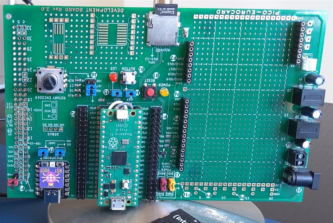
The Pi Pico Eurocard is a development board for the Raspberry Pico, designed by shabaz. In this post, I'm presenting four C projects that I've tested with the kit. Three of the examples are not mine. I adapted them (pin assignments), to work with the kit's hardware.

We'll test:

  • rotary encoder, with PIO
  • gpio pins, with PIO, with FreeRTOS
  • SD Card, with FatFS

image

Prerequisite: you can build and run the pico-examples from the C SDK for Pico.

Project 1: SD Card with FatFS

build from source

carlk3 wrote a port of FatFS for the Pico. I'm adapting it for the EuroCard. Download his port, with examples, from github.

git clone --recurse-submodules https://github.com/carlk3/no-OS-FatFS-SD-SPI-RPi-Pico.git

The project uses the same CMake mechanism as the pico-examples for the C SDK. I'm using the FatFS_SPI example. The CMake file is no-OS-FatFS-SD-SPI-RPi-Pico/example/CMakeLists.txt. One change is required, to select either USB or UART for the print output. I use the EuroCard with the on-board PicoProbe. That taps into the Pico's UART.

pico_enable_stdio_uart(FatFS_SPI_example 1)
pico_enable_stdio_usb(FatFS_SPI_example 0)

The source also needs a change, to define the IO pins that are connected to the SD Card on the EuroCard.
image
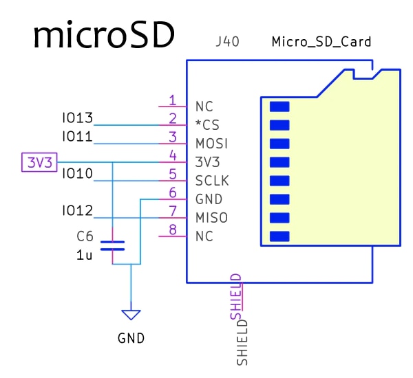
image source: shabaz
EuroCard Pico pin function
*CS IO13 SPI1 CSn
MOSI IO11 SPI1 TX
SCLK IO10 SPI1 SCK
MISO IO12 SPI1 RX

You define these pins in hw_config.c:

// Hardware Configuration of SPI "objects"
// Note: multiple SD cards can be driven by one SPI if they use different slave
// selects.
static spi_t spis[] = {  // One for each SPI.
    {
        .hw_inst = spi1,  // SPI component
        .miso_gpio = 12,  // GPIO number (not pin number)
        .mosi_gpio = 11,
        .sck_gpio = 10,
        .set_drive_strength = true,
        .mosi_gpio_drive_strength = GPIO_DRIVE_STRENGTH_2MA,
        .sck_gpio_drive_strength = GPIO_DRIVE_STRENGTH_2MA,

        // .baud_rate = 1000 * 1000,
        //.baud_rate = 12500 * 1000,  // The limitation here is SPI slew rate.
        .baud_rate = 25 * 1000 * 1000, // Actual frequency: 20833333. Has
        // worked for me with SanDisk.        

        .dma_isr = spi_dma_isr
    }
};

// Hardware Configuration of the SD Card "objects"
static sd_card_t sd_cards[] = {  // One for each SD card
    {
        .pcName = "0:",           // Name used to mount device
        .spi = &spis[0],          // Pointer to the SPI driving this card
        .ss_gpio = 13,             // The SPI slave select GPIO for this SD card
        .set_drive_strength = true,
        .ss_gpio_drive_strength = GPIO_DRIVE_STRENGTH_2MA,
        //.use_card_detect = false,        

        // State variables:
        .m_Status = STA_NOINIT
    }
};

This would be a good time to build the code.
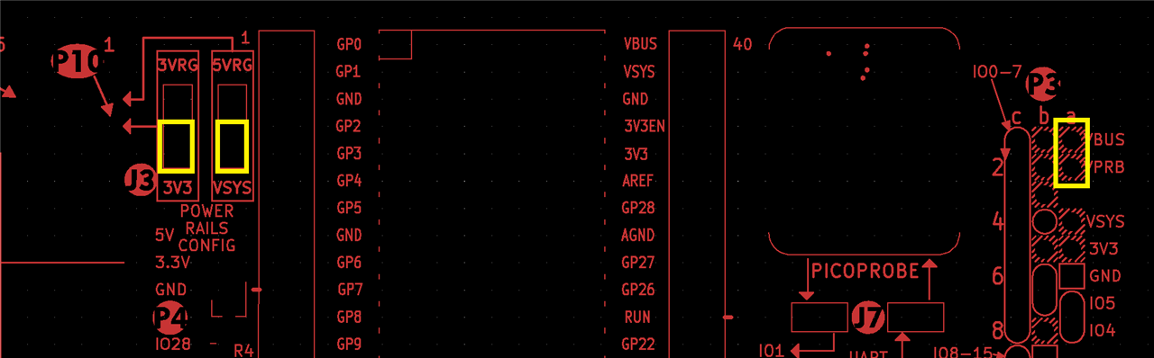
Power

For this example, I'm using the PicoProbe's supply to power the EuroCard and Pico.
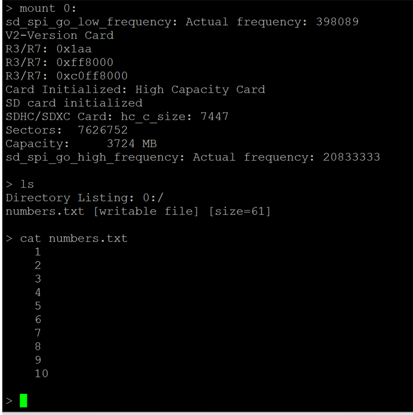
image

Test

Load the firmware to the Pico and insert an SD Card. This can be done with the power on. Connect a terminal program to the PicoProbe's COM port, 115200, 8, 1, N. The example uses escape characters to clear lines, set cursor, format code. The terminal needs to understand these escape characters (e.g.: PuTTY). The built-in terminal of VSCode will not work for this example.

image

VSCode project, with ul2 executable:

no-OS-FatFS-SD-SPI-RPi-Pico_20221111.zip

Project 2: Rotary Encoder with PIO

This project is a PIO Quadrature Encoder by Jamon Terrell. It uses the PIO state machines to decode the movement / position of the rotary encoder on the EurCard. I 've adapted it for the pins used by shabaz.

image

When you connect a serial monitor or terminal (the VSCode one works for this example), it will show the position of the encoder, each time you move it. If you are new to PIO, it's an example that uses a fairly simple PIO design.
Use the same power settings as project 1.
For details on this project, check the blog Pico PIO state machine implements a peripheral: Rotary Decoder. The VSCode archive is attached to that post.

Project 3: add a CAN peripheral with PIO

Here, PIO state machines are used to build a CAN block. It's a more complex example - not to build,  but to understand. It's an adaption of Kevin O'Connor's can2040 library.

image

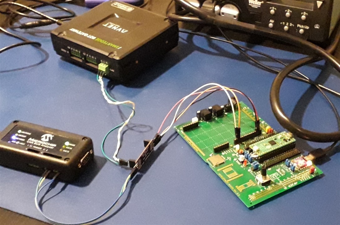
The project requires additional hardware: either a CAN tranceiver, or the  poor man's CAN bus. And a counterpart to talk to. The PicoProbe can again be used to power the solution, like project 1. For details, check the blog Pico PIO state machine implements a peripheral: CAN. The VSCode archive is attached to that post.

Project 4: programmable Lab switch

This one uses FreeRTOS, to build a Lab switch that can control a set of relays, FETs, .... The programming language is SCPI. It can be controlled from LabVIEW, pyvisa and other SCPI savvy solutions.

You don't have permission to edit metadata of this video.
Edit media
x
image
Upload Preview
image

You can test this with the on-board LED, or attach relais to the gpio pins that you control with.
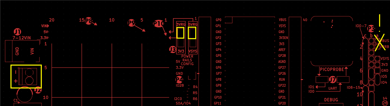
Power

When you use relays, it's best to use the external power option. Don't forget to remove the jumper, to cut the PicoProbe power. 

image

This is a series of articles, step by step. VSCode is attached to each blog. The code for the EuroCard is available on the last post. 

Happy Prototyping!

  • Sign in to reply
  • shabaz
    shabaz over 2 years ago in reply to Jan Cumps

    Done. It's a lot more usable now. Also made the diagrams a bit more eye-friendly when printed (everything large and readable).

    • Cancel
    • Vote Up 0 Vote Down
    • Sign in to reply
    • More
    • Cancel
  • shabaz
    shabaz over 2 years ago in reply to Jan Cumps

    Great, I have added it too.

    • Cancel
    • Vote Up 0 Vote Down
    • Sign in to reply
    • More
    • Cancel
  • shabaz
    shabaz over 2 years ago in reply to Jan Cumps

    Missed seeing this because the system defaults to "comment notifications" off..

    Anyway, I will add all these points into the doc. Incidentally I added the polarity to the silkscreen in a later dot-revision of the board, but will go back and also add the size, since that's useful information too (and I have space in that corner of the board). I've also increased the size of the text labels alongside each pin of the Pico, to make it a lot more eye-comfortable.

    • Cancel
    • Vote Up 0 Vote Down
    • Sign in to reply
    • More
    • Cancel
  • Jan Cumps
    Jan Cumps over 2 years ago in reply to shabaz

    and:

    • maybe we can use pico_eurocard as tag in e14 posts. You could then make a hyperlink of that last sentence in the quick guide:

    /search?q=*#serptag=pico_eurocard&serpsort=date%20desc

    • Cancel
    • Vote Up 0 Vote Down
    • Sign in to reply
    • More
    • Cancel
  • Jan Cumps
    Jan Cumps over 2 years ago in reply to shabaz
    • Using the PicoProbe -> item 8: 2 remarks
      Maybe make it explicit (bold, red, flashing font) that the PicoProbe power jumper should not be placed, when either the Pico's USB is plugged in, or an external source is used?
      You advise to not use the 2 USB cables, but I think there is a valid reason to do that: when you are developing a Pico USB design. As far as I can see, there are no consequences when plugging in both, as long as the jumper of remark 1 isn't placed.

      A quickguide section with the different power scenarios as a drawing - can be clearer than text.

    • your PCB has numbers-in-circles near the connectors. You could use them in the quickguide (when talking about a jumper, connector.

    • mention the barrel size and polarity of J1.
    • Cancel
    • Vote Up 0 Vote Down
    • Sign in to reply
    • More
    • Cancel
>
element14 Community

element14 is the first online community specifically for engineers. Connect with your peers and get expert answers to your questions.

  • Members
  • Learn
  • Technologies
  • Challenges & Projects
  • Products
  • Store
  • About Us
  • Feedback & Support
  • FAQs
  • Terms of Use
  • Privacy Policy
  • Legal and Copyright Notices
  • Sitemap
  • Cookies

An Avnet Company © 2025 Premier Farnell Limited. All Rights Reserved.

Premier Farnell Ltd, registered in England and Wales (no 00876412), registered office: Farnell House, Forge Lane, Leeds LS12 2NE.

ICP 备案号 10220084.

Follow element14

  • X
  • Facebook
  • linkedin
  • YouTube