element14 Community
element14 Community
    Register Log In
  • Site
  • Search
  • Log In Register
  • About Us
  • Community Hub
    Community Hub
    • What's New on element14
    • Feedback and Support
    • Benefits of Membership
    • Personal Blogs
    • Members Area
    • Achievement Levels
  • Learn
    Learn
    • Ask an Expert
    • eBooks
    • element14 presents
    • Learning Center
    • Tech Spotlight
    • STEM Academy
    • Webinars, Training and Events
    • Learning Groups
  • Technologies
    Technologies
    • 3D Printing
    • FPGA
    • Industrial Automation
    • Internet of Things
    • Power & Energy
    • Sensors
    • Technology Groups
  • Challenges & Projects
    Challenges & Projects
    • Design Challenges
    • element14 presents Projects
    • Project14
    • Arduino Projects
    • Raspberry Pi Projects
    • Project Groups
  • Products
    Products
    • Arduino
    • Avnet Boards Community
    • Dev Tools
    • Manufacturers
    • Multicomp Pro
    • Product Groups
    • Raspberry Pi
    • RoadTests & Reviews
  • Store
    Store
    • Visit Your Store
    • Choose another store...
      • Europe
      •  Austria (German)
      •  Belgium (Dutch, French)
      •  Bulgaria (Bulgarian)
      •  Czech Republic (Czech)
      •  Denmark (Danish)
      •  Estonia (Estonian)
      •  Finland (Finnish)
      •  France (French)
      •  Germany (German)
      •  Hungary (Hungarian)
      •  Ireland
      •  Israel
      •  Italy (Italian)
      •  Latvia (Latvian)
      •  
      •  Lithuania (Lithuanian)
      •  Netherlands (Dutch)
      •  Norway (Norwegian)
      •  Poland (Polish)
      •  Portugal (Portuguese)
      •  Romania (Romanian)
      •  Russia (Russian)
      •  Slovakia (Slovak)
      •  Slovenia (Slovenian)
      •  Spain (Spanish)
      •  Sweden (Swedish)
      •  Switzerland(German, French)
      •  Turkey (Turkish)
      •  United Kingdom
      • Asia Pacific
      •  Australia
      •  China
      •  Hong Kong
      •  India
      •  Korea (Korean)
      •  Malaysia
      •  New Zealand
      •  Philippines
      •  Singapore
      •  Taiwan
      •  Thailand (Thai)
      • Americas
      •  Brazil (Portuguese)
      •  Canada
      •  Mexico (Spanish)
      •  United States
      Can't find the country/region you're looking for? Visit our export site or find a local distributor.
  • Translate
  • Profile
  • Settings
Industrial Automation
  • Technologies
  • More
Industrial Automation
Blog Stepper Motor Control with Hercules High-End Timer - Part 7: HET Assembly Language Test
  • Blog
  • Forum
  • Documents
  • Quiz
  • Events
  • Polls
  • Files
  • Members
  • Mentions
  • Sub-Groups
  • Tags
  • More
  • Cancel
  • New
Join Industrial Automation to participate - click to join for free!
  • Share
  • More
  • Cancel
Group Actions
  • Group RSS
  • More
  • Cancel
Engagement
  • Author Author: Jan Cumps
  • Date Created: 10 Jun 2017 3:51 PM Date Created
  • Views 3637 views
  • Likes 5 likes
  • Comments 9 comments
  • stepper_motor
  • boosterpack
  • drv8711
  • texas_instruments
  • hercules
  • launchpad
Related
Recommended

Stepper Motor Control with Hercules High-End Timer - Part 7: HET Assembly Language Test

Jan Cumps
Jan Cumps
10 Jun 2017

I'm trying to control an unknown stepper motor with the high-end timer (NHET) module of a Texas Instruments Hercules microcontroller

image

I got a freebie from TI almost a year ago. An unknown stepper motor, a driver board and a Hercules RM57 LaunchPad. The code to run the motor was expected to arrive too (it was an assignment for an internal) but that never materialised. In this blog series I'm trying to program the NHET module so that it sends the right signals to make the stepper step.


In the 7th blog I create an Assembler program for the HET submodule.


Hercules High-End Timer

Hercules microcontrollers have a particular type of timer on board. It's an autonomous sub-controller.

The difference with your typical timer is that you don't set registers to control it.

You write a program in the HET assembly language.

The asm commands are also different from those of a controller or a processor. Everything is related to timer, angular functions, tight control of timer loop.

Often they can do several things in parallel during a single click of the HET clock.


image


And the module can interact with the ARM controller(s) on the Hercules - memory access and interrupts.

Expert programmers can achieve amazing things.

It's possible to handle the whole server motor control (ramp up, constant speed and ramp down) in the HET module.

The ARM would just set the number of steps to take and go to deep sleep. I'd like to achieve that in this blog series.


You don't have permission to edit metadata of this video.
Edit media
x
image
Upload Preview
image


I have another example published by TI where the whole i²c protocol is implemented in the HET assembly language.


HET Test Program

Today I just want to see if I can get a HET program assembled and linked into my code, and have a HET pin generate a PWM signal.

image

The program is a little more complex than it can be, because it allows for flexible period - something we can ignore here.


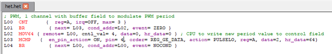
; PWM, 1 channel with buffer field to modulate PWM period
L00  CNT      {  reg=A, irq=OFF, max= 3 }
L01  BR        { next= L03, cond_addr=L02, event= ZERO }
L02  MOV64 { remote= L00, cntl_val= 4, data=0, hr_data=0 } ; CPU to write new period value to control field
L03  MCMP   {  en_pin_action= ON, pin= 4, order= REG_GE_DATA, action= PULSELO, reg=A, data=2, hr_data=64}
L04  BR        { next= L00, cond_addr=L00, event= NOCOND }


Don't try to understand this unless you want to learn the assembler language. A manual is available from TI's Hercules product page.

The only thing that's interesting for this exercise is knowing that this code will generate a 234 kHz PWM with 50% duty cycle on HET pin 4.


image

I've chosen PIN 4 deliberately because that matches the stepper pin of the DRV8711 Stepper Driver BoosterPack.

There's a HET IDE that asists you when writing code (and can integrate with a simulator to pre-test your design on a PC).

You can also assemble the code from the IDE. This will generate a .c and a .h file. They will end up in your project in the next step:


Configure Hercules to Run the HET Code

Like the other modules, HET is configured in HALCoGen. First thing to do is enable the driver:

image


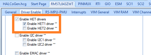
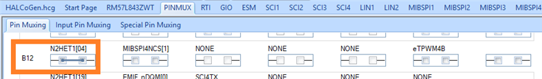
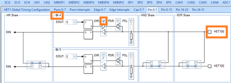
This will take care that HALCoGen creates the driver code for the timer. Then we set the PINMUX so that NHET1 pin 4 is active.

(not really really needed because it's the default assignment for the pin, but it helps finding conflicts later on)

image


On the NHET module itself, you define the frequency, and say that you want to use HET assembly.

(This module can also be configured as a straightforward PWM generator without programming)

image

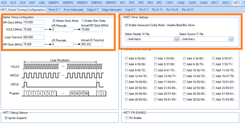
The .h and .c files that we select here are the ones generated by the HET IDE when you pressed the assembler.

When you press the HALCoGen "Generate Code" button later on, thes files will be copied into your Hercules project code.

As a last step in this blog, I'll show how all of this can be scripted so that both the assembly and copy step are automatically done as part of a CCS build.


The last step in the HET configuration pages is to make HET1 pin 4 an output pin:

image


CCS Project Settings and Automating the Build

I prefer to minimise the number of manual steps when building a firmware binary. If at all possible, no manual steps, so that a build is repeatable.

In this case it is possible because the HET suite for the Hercules come with a command line assembler.

In CCS, you have the option to add commands before or after a build, so that's a perfect location to put these.


image

I have created my HET IDE project in the het subfolder of the CCS project.

For some reason, the build steps are executed from a folder one level in the project (too lazy to find out which one), so we have to prepend all folders with  ..\.

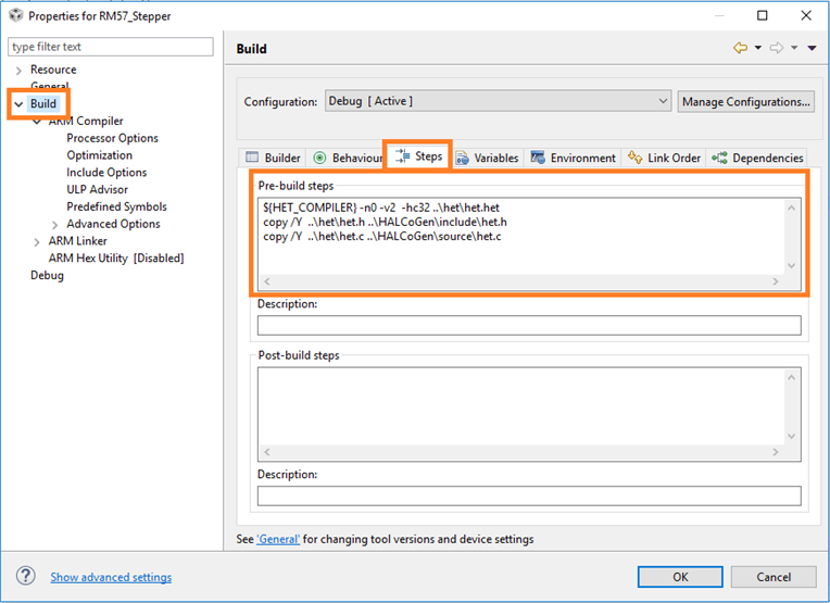
The first line assembles the .het source into  .c and .h files in the het folder:

${HET_COMPILER} -n0 -v2  -hc32 ..\het\het.het


The next two lines copy the .h and .c into the HALCoGen project source:

copy /Y  ..\het\het.h ..\HALCoGen\include\het.h
copy /Y  ..\het\het.c ..\HALCoGen\source\het.c


That's all. A little bit of scripting automates the whole thing. The results can be found back in the console after build:

**** Build of configuration Debug for project RM57_Stepper ****

"D:\\ti\\ccsv7\\utils\\bin\\gmake" -k -j 8 all -O 
"D:\Program Files (x86)\Texas Instruments\Hercules\HET IDE\03.05.01\bin\hetp.exe" -n0 -v2  -hc32 ..\het\het.het
NHET Assembler    Release 1.7
Texas Instruments Incorporated. 
 PASS 1
 PASS 2

 No Errors, No Warnings
copy /Y  ..\het\het.h ..\HALCoGen\include\het.h
        1 file(s) copied.
copy /Y  ..\het\het.c ..\HALCoGen\source\het.c
        1 file(s) copied.
' '
'Building file: ../HALCoGen/source/HL_gio.c'
'Invoking: ARM Compiler'
...


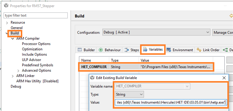
I've registered the HET command line tool in a project parameter, so that the script is PC independent:

image


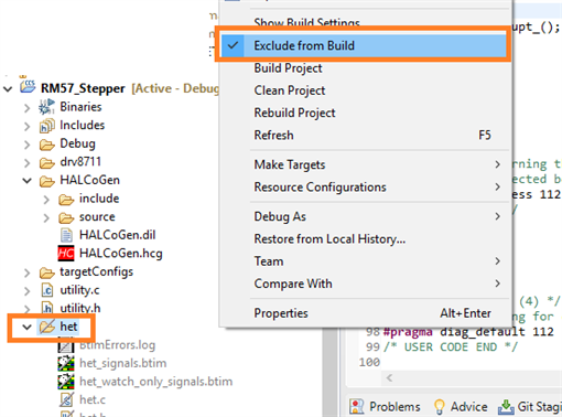
A last point of attention: if the HET project is a subfolder of your CCS project, you'll have to exclude it from compiling. Else you have the het.c file twice in your build and it'll fail.

image


Running the HET code

The easiest part. It runs immediately when you initialise the HET module.


// ...
#include "HL_het.h"
// ...

int main(void)
{
// ...
    hetInit();
// ...


The oscilloscope grab at the start of the blog is the actual result of running the code of this blog.


In a next blog we'll communicate with the HET sub-controller so that it only generates pulses when we want it, and how we want it.

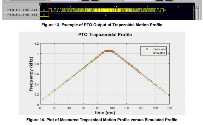
The end-game is to get a signal like this out of the module, based on a ramp profile that we define.

image


Related Blog
Part 1: Hardware Overview
Part 2: Stepper Controller and MSP430 Firmware
Part 3: SPI Commands and Pulse Control
Part 4: Analyse MSP430 PWM Step Signal
Part 5: Hercules RM57 Hardware Provisioning
Part 6: Hercules RM57 SPI
Part 7: HET Assembly Language Test
Part 8: HET Based Pulse Train Output
  • Sign in to reply

Top Comments

  • DAB
    DAB over 8 years ago +1
    Another excellent post Jan. Good detail and screen captures so that the reader can easily follow along. Well done. DAB
  • michaelkellett
    michaelkellett over 8 years ago +1
    Useful blog Jan, I see that the HET has been around since 2010 (at least) and this is the first time I've noticed it !! Motorola (in the days before On and Freescale) offered a complex programmable timer…
  • michaelkellett
    michaelkellett over 8 years ago in reply to Jan Cumps +1
    Is this a business opportunity ( Currently designing/coding an Ethernet UDP RX/TX offload system in VHDL for FPGA - there must be easier ways to make a living !) MK
  • Jan Cumps
    Jan Cumps over 5 years ago

    I'm checking some more advanced timer functions (not related to the stepper motor exercise, more for my own learning)


    TI has an example to generate dynamic PWM signals and measure timing errors, all done within the timers.

    This example is interesting because it tests generating somewhat complex signals (a triangle waveform).

    The signal is made by changing the duty cycle od a PWM dynamically. A discrete low pass filter (a resistor and capacitor) turns those pulses into the analog waveform.


    image


    Because the PWM signal has different duty cycles during a single wave cycle, this signal is interesting to test if the timer can detect precision of a signal's attributes.

    The second part of the timer logic uses this capability. It puts an output pin high (and raises a software trigger too that you can use for counting failures) whe the duty cycle is outside a given range.

    You see that in the blue trace.


    Everything, except the optional trigger, consumes 0 CPU cycles. Really 0 cycles on the Hercules. I can stop the controller in the debugger and both timer functions will happily continue working.


    image


    I'll write a post on this, because TI's example needs some changes to make it work on a LaunchPad that aren't documented ...

    • Cancel
    • Vote Up +1 Vote Down
    • Sign in to reply
    • More
    • Cancel
  • Jan Cumps
    Jan Cumps over 8 years ago

    Capture of both the SPI and PWM part:


    image


    Signals on all lines, but the motor doesn't move yet.

    Although I thought I was sending the identical SPI commands from Hercules as those from the official' MSP example, something may be missing.

    When I pull the DRV out of sleep, it consumes 13 ma instead of the 600 mA it draws with the MSP430 app...

    Reset and nSLeep aren't shown here. I've measured those with a multimeter.


    But this is good news by itself: there's no GAP in capabilities - the Hercules can provide the required signals.

    • Cancel
    • Vote Up +1 Vote Down
    • Sign in to reply
    • More
    • Cancel
  • michaelkellett
    michaelkellett over 8 years ago in reply to Jan Cumps

    Is this a business opportunity image


    ( Currently designing/coding an Ethernet UDP RX/TX offload system in VHDL for FPGA - there must be easier ways to make a living !)


    MK

    • Cancel
    • Vote Up +1 Vote Down
    • Sign in to reply
    • More
    • Cancel
  • Jan Cumps
    Jan Cumps over 8 years ago in reply to michaelkellett

    The toolset is good  - not spectacular though.

    The documentation and technical manual is very good.

    What's missing though are good tutorials that go beyond a simple PWM.


    Luckily there are a set of good appnotes: timer programmed as an i²c master device, a sine and tringle wave generator, the excellent appnote that I'm using here, some examples to generate 3 phase signal with deadband.


    What I notice however is that all good examples come from a TI employee. It's hard to find an example that's not from their stable.

    I think that all the experts are internal and that they hire them as consultants to the customers image

    • Cancel
    • Vote Up 0 Vote Down
    • Sign in to reply
    • More
    • Cancel
  • michaelkellett
    michaelkellett over 8 years ago

    Useful blog Jan, I see that the HET has been around since 2010 (at least) and this is the first time I've noticed it !!


    Motorola (in the days before On and Freescale) offered a complex programmable timer but they never supported it with decent tools so it wasn't used much.


    It looks as if TI support this a lot better - I wonder if it might appear on non Hercules ARMs at some time.


    MK

    • Cancel
    • Vote Up +1 Vote Down
    • Sign in to reply
    • More
    • Cancel
>
element14 Community

element14 is the first online community specifically for engineers. Connect with your peers and get expert answers to your questions.

  • Members
  • Learn
  • Technologies
  • Challenges & Projects
  • Products
  • Store
  • About Us
  • Feedback & Support
  • FAQs
  • Terms of Use
  • Privacy Policy
  • Legal and Copyright Notices
  • Sitemap
  • Cookies

An Avnet Company © 2025 Premier Farnell Limited. All Rights Reserved.

Premier Farnell Ltd, registered in England and Wales (no 00876412), registered office: Farnell House, Forge Lane, Leeds LS12 2NE.

ICP 备案号 10220084.

Follow element14

  • X
  • Facebook
  • linkedin
  • YouTube