


In this test, I want to be able to set up data output through the serial port to a host machine connected over the USB port. I’d see data capture as a typical use case for devices with some control over what data is sent, and when. I’m not creating a host application to process the data, I will just use a terminal application to view it.
TL;DR:
- The RX65N can be configured for Host (USB A) or Peripheral (USB B)
- Peripheral use requires the same port as the debugger so it is not possible to use the serial interface and debug at the same time: a choice has to be made and the board re-configured accordingly. This makes development slow and, frankly, a pain.
- The FIT module for serial interfacing generates the wrong code: Port/Pin settings are incorrect so the board will Receive from a host terminal but not Transmit back to that host. Fortunately, Jan Cumps has working code so I didn’t have to spend time getting this right, although I did investigate what the issue was to come to the conclusion about the FIT module.
- Developing serial interaction on this board is a right royal pain in the neck. The board has to be reconfigured - with the dip switches SW1 and SW2 - in order to swap between debugging and using the serial interface which happens with extreme frequency. I have to detach/attach the hook up wires to the breadboard so I can orient the board to access the switches. It also means that the only way of debugging is to use copious output to the LCD. They really should have designed this to work together or to break out the serial interface to a different connector. It ends up being quicker to create new projects to test things when it doesn't require the serial interface to do that test.
- The application now communicates with a Host PC. The terminal application on the Host can send commands to the board: + to turn on transmit; - to turn off transmit. The board will send the measured data to the Host every second as a comma-delimited string. It would be easy to extend the command set to provide further control over, for example, timing and data sent.
Introduction
There is a difficulty in this: the board can use the USB UART/Serial connection for either that purpose OR for debugging but not both simultaneously. Jan mentioned this in his review and had a workaround not available to me unfortunately. Still, it wouldn’t be the first time I’ve had that problem and the MCU has a screen attached for outputting. However, it has made creating and testing the code for this feature a real pain in the neck because the board has to be reconfigured (dip switch settings) between development and test.
I expect that if a serial interface was a major feature in an app being developed, investment in an external E2Lite debugger would be useful. Renesas has provided a location for headers to be soldered to attach such a device but unhelpfully positioned it under the LCD’s flex PCB:
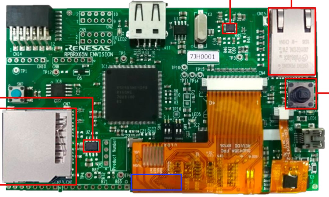
The blue rectangle highlights the position of the header (ignore the red lines/boxes)
To use it, the LCD would have to be unstuck from the back of the PCB and left flapping in the breeze, resting on the header cable to the external debugger. I can see that ending in tears frankly, so I’m not really sure what they were thinking of here. If they'd taken it the other way, over the small IC marked with the red box it would have been more convenient - that IC is a controller for Ethernet and is a User Fit part so once in place, the LCD wouldn't need disturbing again.
The available samples and application notes are all based around the use of FIT modules USB Basic and USB Peripheral Communications Device Class Driver (PCDC). Let me say now: I could not get this to work, no matter what I tried. It would open a USB connection and report success status, and the host would enumerate the board correctly based on the descriptors set up, but there was never any response that it had been configured and thus, could not be used to send/receive data. It didn’t help that I couldn’t debug it so I had little information to go on. I tried this in Windows 10 and native MacOs (two different machines) with no success.
Jan Cumps has code working that uses the Serial Communications Interface (SCI) FIT module to open a UART/Serial connection to a host: his application will echo back a received character and toggle the LED on each character received. I, however, could not get this to work initially. Again, no matter what I tried I was getting no response at the host and the board’s led was not toggling. I’d spent 1.5 days investigating these issues and was about to give up. I was scoping the RX pins and seeing data arriving - the waveform was captured - but the LED stayed off and the TX pin stayed unchanging. I’d really got to the point that I’d assume I’d damaged something removing the LCD and soldering headers but then….then…it just started working. I still have no idea why, I loaded no new code on it, didn’t configure the host terminal app any different, nothing. I know that something must have changed but I have no idea what.
Not that I could get my original code working, that still stayed non-functional. I suspect the FIT modules are not configuring properly on the ports and pins but I can’t spot it. Why reach that conclusion? Jan had already confirmed that the code generated by the FIT module for SCI was doing so incorrectly and the port/pin configuration needed one additional setting.
Not an auspicious start and this is the first time during the road test that the FIT modules have caused me trouble. I’m not going to spend more time trying to find out the trouble with the two modules I had intended to use for this, but will take the route that Jan did with the SCI module - I believe that will work for my purposes. So I have a demo app now that will echo data back to the host and thus a mechanism for receiving data (instructions) and transmitting data (responses).
Approach
I don’t want to make this overly complicated. My intention is to develop the app further with the following features:
- Receive a + character to turn on data transfer
- Receive a - character to turn off data transfer
- Transmit volts, amps, power, temperatures every second whilst requested.
This should prove the capability and could be extended. I can imagine responding to SCPI commands, for example, to tune the data sent as well as the frequency. When I finished post 6, implementing the ADC and I2C functionality, it wasn’t very stable because I was using triggers to drive the ADC but hadn’t dealt with any issues such as interrupting interrupts. I’d suggested that a better approach would be to use a Compare and Match Timer and to drive the ADC conversions on an elapsed time basis. I’ve changed the code to do this and it now:
- reads volts, amps, power and iMon every 500ms
- updates elapsed time every 1sec
- updates the temperatures every 15secs
The code is much cleaner and the interface is stable.
FIT Module
As usual, configuring the FIT module is very simple: select the channel to use, then the Pins, then generate:
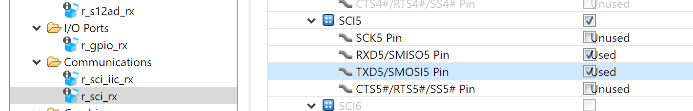
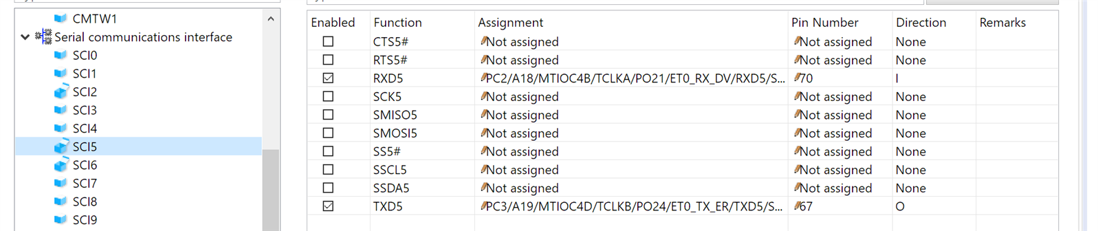
It’s worth noting that Smart Configurator automatically selects the right pins for the RX65N for me. As noted above, Smart Configurator generates code that won’t work without amendment. Interestingly, it generates two files for Port/Pin configuration: Pin.C which contains configuration for ALL Ports/Pins; and individual files, r_xxx_rx_pinset.c, specifically for the module (so r_sci_rx_pinset.c in this case). For the application you can call the relevant file - typically, this is in Pin.C because there is usually more than one module to be setup. The code in the two files seems to be different and in r_sci_rx_pinset.c the code that is needed for it to work appears. This has been raised on the Forum previously by Jan but was dismissed, or misunderstood, by a responder (who wasn’t a Renesas employee, they haven’t responded). I have re-raised this with more information and I shall report on what response is given, if any.
Updated Application
With the module code generated, I am now able to send commands to the board and receive data. I am using ‘+’ to turn on data transmission, and ‘-‘ to turn it off. The UI has been re-arranged somewhat to show the transmission status, TX On or TX Off. Data is being sent every second as a comma-delimited string: Volts, Amps, Power, iMon, Bridge Rectifier Temp, Case Temp, Mosfet Temp, Linear Regulator 1 Temp, Linear Regulator 2 Temp.
The short video shows this in action:
Summary Thoughts
Exceptionally to the other FIT modules I used, this one was not simple to get up and running. The application notes and samples are mostly geared towards the drivers and not an actual working application (I did find one in the end.) I could not get the modules working that could be used for Peripheral serial connections at all, so it’s fortunate that Jan had a working application using the serial communication interface module. I still have no idea why Jan’s application did not work and then did - I had uploaded no code, changed no configuration or plugged/unplugged anything. Nevertheless I will add this: the documentation for the SCI module is very good and I could use it to adapt Jan’s program for what I needed. Apart from the one problem noted above, the generated code, yet again, did all the heavy-lifting. I accept bugs in code as a way of life so I’m still highly impressed with the development support offered.
I have attached the final application code below. This is the cleaned up version with serial interfacing.
Further Entries
This is the last application change I will make in this road test so there will be no further updates apart from the actual Road Test Review post:
Part Three: Development Software
Part Four: Brief notes, first part
Part Five: Static Setup of the GUI
Part Six: Getting the Display Working
Part Seven: USB/Serial Interfacing (this post)
Also, worth reading Jan Crump's road test as he's taking a more technical approach.
Top Comments