Goal: write a design that exchanges data with an external EEPROM IC. I have a set of 25LC256 SPI 256 Kbit EEPROMs, so I'll see if I can communicate with them, in VHDL.
At this point, I'm not going to use the Xilinx MicroBlaze or SPI IPs, although they are a good fit for this kind of exercise. It 'll be a HDL exercise.
Until now, the projects I did for the Spartan-7 were ports from things I did on a Spartan-6, or little try-outs. One of the asks of the 7 Ways to Leave Your Spartan-6 FPGA program is to build a design with a sensor. I was looking for SPI sensors in my parts bin. Didn't find any, but I found this EEPROM. I think it can become a nice project. Maybe my little LDR/XADC post counts for the sensor exercise...

Functionality:
- Use the 4 slider buttons as memory address setters, for read and write operation.
- When pushing one of the 4 push buttons, write the value 1 .. 4 to that memory address to EEPROM.
- and then immediately load the value represented by the 4 slide buttons, and light up the corresponding LED.
- When pressing reset, dim all LEDs, unitl released. Then load the value represented by the 4 slide buttons, and light up the corresponding LED.
Components:
- 25LC256 SPI EEPROM
- Arty S7 board (any FPGA would do) , with 4 slide switches, 4 push buttons, 4 LEDs and 4 GIO pins
- little breadboard
- some patch and jumper cables
- 3 10K pull-up resistors
- power for the EEPROM. I'm tapping it from the Arty board.
|
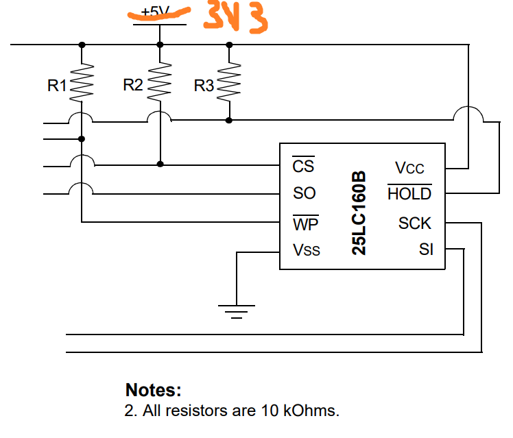
Side note: handling active low pins Microchip app notes aren't consistent. Some pull unused and ~CS up with a resistor, some tie unused to VCC and don't pull up ~CS
|
Hardware and wiring

Power and ground for the EEPROM come from the Arty board's PMOD JA. The 4 SPI lines are pin 1 -> 4 of that same PMOD.
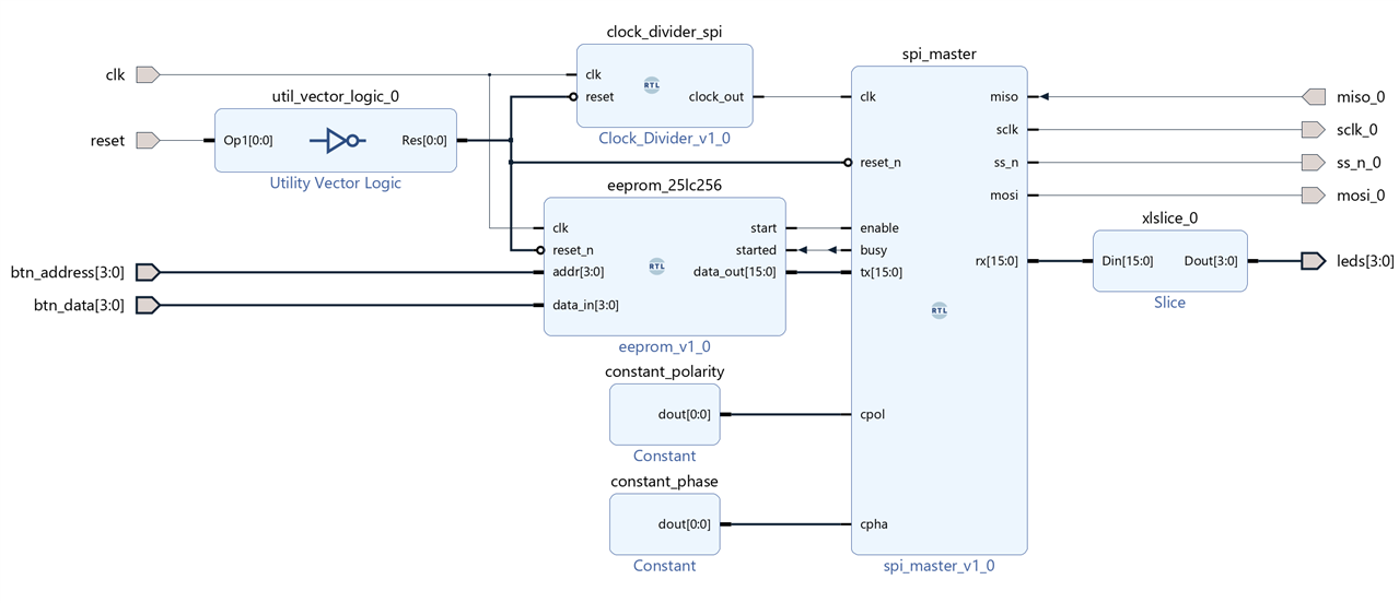
FPGA blocks
The SPI master is from Iman Nematollahi, available on github. Clock divider is the same one used in my previous blog. The eeprom_25lc256 is a VHDL design that I have yet to make (part 2 of this project). On the left side you find the push buttons for reset, data generation and the slide buttons to set EEPROM address. On the right side are the 4 SPI signals and the 4 LEDs, directly wired to what the SPI block reads from the EEPROM.
note: the NOT gate after the reset pin should not be there. The Arty has this implemented as pulled high, so it can directly go into the downstream blocks.

Good thing that I blogged this. On the image at the top, you can see that I put a wrong IC on the breadbord: an i2c EEPROM. I would not have spotted that if I didn't take that photo. I left the photo there because it looks good ;)


-

Jan Cumps
-
Cancel
-
Vote Up
0
Vote Down
-
-
Sign in to reply
-
More
-
Cancel
-

Jan Cumps
in reply to Jan Cumps
-
Cancel
-
Vote Up
0
Vote Down
-
-
Sign in to reply
-
More
-
Cancel
Comment-

Jan Cumps
in reply to Jan Cumps
-
Cancel
-
Vote Up
0
Vote Down
-
-
Sign in to reply
-
More
-
Cancel
Children