element14 Community
element14 Community
    Register Log In
  • Site
  • Search
  • Log In Register
  • Community Hub
    Community Hub
    • What's New on element14
    • Feedback and Support
    • Benefits of Membership
    • Personal Blogs
    • Members Area
    • Achievement Levels
  • Learn
    Learn
    • Ask an Expert
    • eBooks
    • element14 presents
    • Learning Center
    • Tech Spotlight
    • STEM Academy
    • Webinars, Training and Events
    • Learning Groups
  • Technologies
    Technologies
    • 3D Printing
    • FPGA
    • Industrial Automation
    • Internet of Things
    • Power & Energy
    • Sensors
    • Technology Groups
  • Challenges & Projects
    Challenges & Projects
    • Design Challenges
    • element14 presents Projects
    • Project14
    • Arduino Projects
    • Raspberry Pi Projects
    • Project Groups
  • Products
    Products
    • Arduino
    • Avnet Boards Community
    • Dev Tools
    • Manufacturers
    • Multicomp Pro
    • Product Groups
    • Raspberry Pi
    • RoadTests & Reviews
  • Store
    Store
    • Visit Your Store
    • Choose another store...
      • Europe
      •  Austria (German)
      •  Belgium (Dutch, French)
      •  Bulgaria (Bulgarian)
      •  Czech Republic (Czech)
      •  Denmark (Danish)
      •  Estonia (Estonian)
      •  Finland (Finnish)
      •  France (French)
      •  Germany (German)
      •  Hungary (Hungarian)
      •  Ireland
      •  Israel
      •  Italy (Italian)
      •  Latvia (Latvian)
      •  
      •  Lithuania (Lithuanian)
      •  Netherlands (Dutch)
      •  Norway (Norwegian)
      •  Poland (Polish)
      •  Portugal (Portuguese)
      •  Romania (Romanian)
      •  Russia (Russian)
      •  Slovakia (Slovak)
      •  Slovenia (Slovenian)
      •  Spain (Spanish)
      •  Sweden (Swedish)
      •  Switzerland(German, French)
      •  Turkey (Turkish)
      •  United Kingdom
      • Asia Pacific
      •  Australia
      •  China
      •  Hong Kong
      •  India
      •  Korea (Korean)
      •  Malaysia
      •  New Zealand
      •  Philippines
      •  Singapore
      •  Taiwan
      •  Thailand (Thai)
      • Americas
      •  Brazil (Portuguese)
      •  Canada
      •  Mexico (Spanish)
      •  United States
      Can't find the country/region you're looking for? Visit our export site or find a local distributor.
  • Translate
  • Profile
  • Settings
FPGA
  • Technologies
  • More
FPGA
Blog Building (and testing) the Cheap and Tiny FPGA board.
  • Blog
  • Forum
  • Documents
  • Quiz
  • Events
  • Polls
  • Files
  • Members
  • Mentions
  • Sub-Groups
  • Tags
  • More
  • Cancel
  • New
Join FPGA to participate - click to join for free!
  • Share
  • More
  • Cancel
Group Actions
  • Group RSS
  • More
  • Cancel
Engagement
  • Author Author: michaelkellett
  • Date Created: 31 Dec 2018 3:56 PM Date Created
  • Views 2087 views
  • Likes 12 likes
  • Comments 8 comments
  • fpga
Related
Recommended

Building (and testing) the Cheap and Tiny FPGA board.

michaelkellett
michaelkellett
31 Dec 2018

Those of you with long memories will remember the first blog about this board:

Ultra cheap and Tiny FPGA Board


I've built up a couple of boards and got them running some very simple start up software and VHDL.

The good news is that there are only two small bugs on the board, neither is too grim to fix.


Other E14 members (notably Jan Cumps ) have been Roadtesting the MAX32660 which provides one half of the good stuff on this board.

My approach to coding the processor is very different so I've hit a different stream of snags and I'll talk a little about one of them and it solution.


But first the building !


The MAX32660 variant I used comes in a 0.4mm pitch QFN package which is too tricky for pure hand soldering. I used a bought in metal stencil for solder paste printing, hand placed the parts using microscope and tweezers and re-flowed in a CIF drawer type re-flow oven.

The results were quite good, no shorts on either the 0.4mm pitch or 0.5mm pitch QFNs. It's not quite a home process, the screen printer and the oven are a bit pricey for unpaid work - cheaper Chinese alternatives exist.


PCB with solder paste

image


PCB with components before re-flow

image


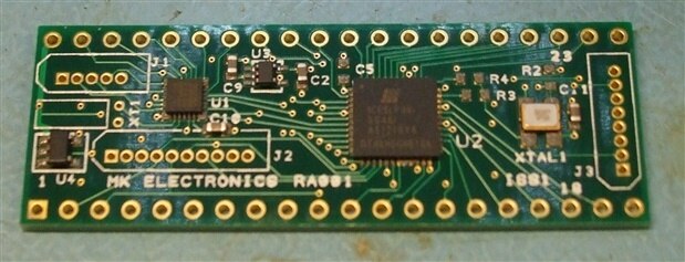
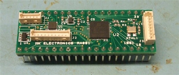
PCB after re-flow and hand soldered parts fitted

image


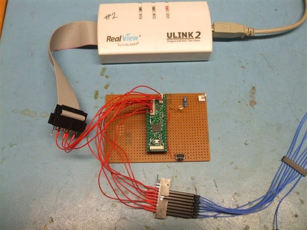
Debugging on Veroboard breakout board with ARM Ulink and logic analyser attached

image


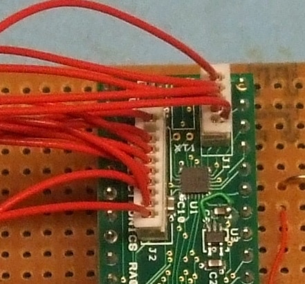
PCB Bugs - C10 fouls J2 and wire link on U3

image


Test Code


The test code on the FPGA just sets up the PLL to turn the 25MHz clock signal from the oscillator chip into a 50MHz signal output on one pin.


The C code on the MAX32660 sets up some IO pins and uses SPI to load the FPGA withe its 100k byte bit pattern. I used bit banged SPI which saves me the trouble of getting the MAX32660 SPI hardware going (I'll do that later.)

But to bit bang you need need to be able to set output pins high and low and you would like to be able to do it reasonably quickly.


To test the speed of pin toggling I wrote this into Maxim's GPIO example project:


while(1)

     {

     GPIO_OutSet(&gpio_out);          //official Maxim way of setting pin

     GPIO_OutClr(&gpio_out);

     }


this is pretty grim in that you need to define gpio_out and set it up like this:


gpio_cfg_t gpio_out;

gpio_out.port = GPIO_PORT_OUT;

gpio_out.mask = GPIO_PIN_OUT;


It's a bit bonkers because the chip only has ONE port - so it must be set to zero but every pin will need you to set its port to zero. I assume this is an attempt to make the code general across the chip family but it is really ugly.


But it gets much, much worse:


When we run it the toggle rate is 0.86MHz, on a processor with 96MHz core clock and a 48MHz peripheral clock - ugh !

There's a quick gain by turning the instruction cache on (why provide example code that doesn't do this ?)


So add


ICC_Enable();


at the beginning of your c code and the toggle rate improves to 2.347MHz, which is better but still dreadful.


The problem is GPIO_OutSet() which is a full on function call, if we replace the calss to the official functions with


gpio->out_set = (1u << 4);

gpio->out_clr = (1u << 4);


the toggle rate gets up to a more respectable 7.97Mhz.


gpio is the single gpio port and is defined in one of the Maxim header files which is how I know about the out_set and out_clr registers, which are NOT documented in the chip's User Manual.


It's not very pretty to do it quite like this so I've defined some macros to make it nicer:


first we define our pins like this:


#define LED GPIO0,4          // I've kept up with allowing more than one port, although it is a bit daft on this processor


then (in a header file where we only have to look at it once) we define the macros:


#define GPIO(g, p) GPIO_(g, p)

#define GPIO_(g, p) g


#define PIN(g, p) PIN_(g, p)

#define PIN_(g, p) p


#define GPIO0    ((mxc_gpio_regs_t*)MXC_BASE_GPIO0)


#define PIN_SET(p) (GPIO(p)->out_set = 1 << PIN(p))

#define PIN_CLR(p) (GPIO(p)->out_clr = 1 << PIN(p))


and now we can toggle the pins with:


PIN_SET(LED);

PIN_CLR(LED);


(In the spirit of full disclosure - I did not write the original version of those macros, that honour belongs to my son, Edward, who did them originally for STM32Fxx IO)


The first person who can explain simply why the macros must be  defined in two steps (or suggest an alternative that works) can have a board of their very own !


Of course the macros PIN_SET and PIN_CLR go at the same speed as gpio->out_set = (1u << 4);


It's 9.25x faster than Maxim's demo code.


I'm thinking I'll make a breakout board next - any suggestions as to what to put on it are welcome - I want something simple that you can't easily do without the FPGA.


MK

  • Sign in to reply

Top Comments

  • shabaz
    shabaz over 6 years ago +5
    Hi Michael, It looks like a fun board : ) I'm not too great on macros, (kind of used to quickly closing any header file, if I cant see it then it doesn't exist : ) so a guess is something to do with needing…
  • Jan Cumps
    Jan Cumps over 6 years ago +4
    I’m trying to break the macro riddle, to see why it is multi step. On paper because I’m away from compilers until Sunday. An idea for a breakout board that’s FPGA-interesting? 2 DACs, so you can build…
  • michaelkellett
    michaelkellett over 6 years ago in reply to jc2048 +4
    It's really not the right FPGA for ethernet, a reasonable MAC would use up half the FPGA, the low speed would make an RMII difficult. The processor could manage but would still need to pump all the Ethernet…
  • michaelkellett
    michaelkellett over 6 years ago in reply to jc2048

    It's really not the right FPGA for ethernet, a reasonable MAC would use up half the FPGA, the low speed would make an RMII difficult.

    The processor could manage but would still need to pump all the Ethernet traffic through SPI.

    This is the kind of FPGA you might use to glue a few audio chips together and maybe do some simple signal processing.


    If I don't get any better ideas I might add the parts needed to make a TEC controller  - I've used a very expensive chip from LT in the past and it might be useful to make a digital replacement.


    There are enough pins to support that and the codec, which might form the basis of a very cool audio device image


    MK

    • Cancel
    • Vote Up +4 Vote Down
    • Sign in to reply
    • More
    • Cancel
  • jc2048
    jc2048 over 6 years ago in reply to michaelkellett

    A CODEC sounds good to me.


    Perhaps an interface so that it could be a standalone music module? MIDI (in, out, and through) would be simplest. Ethernet if you like a challenge.

    • Cancel
    • Vote Up +1 Vote Down
    • Sign in to reply
    • More
    • Cancel
  • michaelkellett
    michaelkellett over 6 years ago in reply to shabaz

    Hmmm, that seems to work fine - I just put it in the MAX32660 code.


    I wonder if I missed something when I transferred it from the original target.


    Any way - I owe you a board but I'll probably make you wait until I've done the breakout board, which so far will have a cheap stereo codec on it.

    But it's not too late to suggest additional goodies.


    Thanks.


    MK

    • Cancel
    • Vote Up +3 Vote Down
    • Sign in to reply
    • More
    • Cancel
  • michaelkellett
    michaelkellett over 6 years ago in reply to Jan Cumps

    I'm thinking of an AD SSM2604, 24 bit, up to 96k sampling rate dual ADC/DAC with I2S audio and I2C control interfaces.

    It will need a 12.288 or 24.576 MHz oscillator for standard high quality audio sampling rates.

    Farnell part number 2457480, about £2 each.

    The FPGA is not well endowed with multipliers so it may be better to attempt DSP on the MAX32660, but it depends on what you want to do.

    The SPI link should be able to manage 25MHz clock rates for maximum of about 3Mbytes/s in each direction, the audio data, even at 32 bits per sample won't exceed 768kbytes/s so should be no problem.


    I'll still have  a lot of FPGA pins spare so I'll need to add something else !

    MK

    • Cancel
    • Vote Up +3 Vote Down
    • Sign in to reply
    • More
    • Cancel
  • DAB
    DAB over 6 years ago

    Very good post.

    Great detective work in finding a good option.


    DAB

    • Cancel
    • Vote Up +2 Vote Down
    • Sign in to reply
    • More
    • Cancel
>
element14 Community

element14 is the first online community specifically for engineers. Connect with your peers and get expert answers to your questions.

  • Members
  • Learn
  • Technologies
  • Challenges & Projects
  • Products
  • Store
  • About Us
  • Feedback & Support
  • FAQs
  • Terms of Use
  • Privacy Policy
  • Legal and Copyright Notices
  • Sitemap
  • Cookies

An Avnet Company © 2025 Premier Farnell Limited. All Rights Reserved.

Premier Farnell Ltd, registered in England and Wales (no 00876412), registered office: Farnell House, Forge Lane, Leeds LS12 2NE.

ICP 备案号 10220084.

Follow element14

  • X
  • Facebook
  • linkedin
  • YouTube