


Decided to expand on my last project:
Problem of the moment:
This board just isn't gonna work out.
Moving to a Kintex 7 board:
Software Defined Transceiver Redux
============================================================
Ordered this board from Amazon:
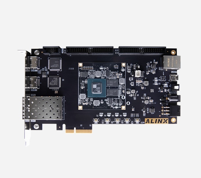
It's similar to the board I used in the last project, except that it has SFP fiber connectors and a larger FPGA.
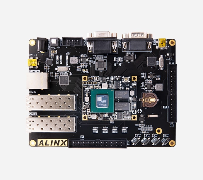
I plan to mate it via fiber to this board:
The complete setup will look something like this:

============================================================
August 30, 2023
The board arrived today:

Retrieved all the associated software and demos from a DropBox this time. Much nicer experience than the wetransfer used with the last board.
============================================================
September 1, 2023
The fiber optic cable and 10G transceivers arrived:

Now all I need is some time.
============================================================

============================================================
September 2, 2023
I haven't described what I'm attempting to do with this project, so here goes...
In the last project I started out with the FPGA/PCIe board in the PC cabinet. Then I put it on a 200mm PCIe riser cable, and then a 600mm riser cable, completely removing it from the interior of the cabinet. The final step was to use the PCIe fiber optic extension device to place the board in another cabinet. This worked out very well. And so I decided to see if I could do something similar with FPGA cards that had SFP transceiver capability.
My first plan was to use something like the second board above (AX7202) attached to a standard 10G fiber NIC card in the PC. I would pack ADC samples in UDP datagrams and stream to the NIC. Code would read the NIC data and write to the Cuda board. But it appears that the Artix-7 cannot do 10G as its GPTs only do 6.5G (I've read some posts that claim it CAN be done, but I have my doubts). So my 2nd plan was to stream the ADC samples from the AX7202 to an AX7A200 (the card I just received). This card would then forward them thru the PCIe interface as my previous setup does.
I can use the AX7A200 to first prototype the ADC transfer capability in a loop-back fashion with it's 2 SFP connectors. Once I have dummy ADC data going out the 1st SFP, then back into the 2nd SFP, and finally to the host thru the PCIe interface I will buy an AX7202 and send dummy ADC data from it to the AX7A200/PCIe to host/Cuda.
After that its just repeating steps already done in the first project: design/build ADC adapter boards, code the Verilog shim for the ADC boards, etc.
As to making it a transceiver this time, I saw those 2 empty 40 pin expansion connectors on the main board and asked myself what I might use them for...
============================================================
September 9, 2023
After upgrading to Ubuntu 23.04 Vivado can no longer see the JTAG devices. I pulled out my old 22.10 Vivado box and started the standalone hardware server program. After much futzing around to get all the port connectivity, firewall rules, etc. properly set I was able to load a test program into the new board via the remote server method. This just blinks the status LEDs:

============================================================
September 10, 2023
I found I can run the standalone hw server on the 23.04 box and use it to load via JTAG. I added it to StartupApplications:

Now I can run Vivado as before, connecting to the JTAG device with a few clicks:

============================================================
September 11, 2023
Cannot yet build a PCIe demo from scratch with Vivado 2022.2. The demos for this board are built with 2017. I have been able to build the LED blinker test, but that doesn't expose PCIe to the bus. I was able to load the 2017 .bin file
I was able to burn the 2017 .bin file from 31_pcie_ram_axilite_usr_bypass.zip, it works:
$ lspci | grep Xilinx
0a:00.0 Memory controller: Xilinx Corporation Device 7022
these work:
/home/Xilinx/Tools/myTools$ sudo ./leds_rw 4
Write 4 bit value: 0xd
smp@Sdr:/home/Xilinx/Tools/myTools$ sudo ./leds_rw 2
Write 4 bit value: 0xb
smp@Sdr:/home/Xilinx/Tools/myTools$ sudo ./leds_rw 1
Write 4 bit value: 0x7

$ sudo ./getid
user 0 0 48
Device base path: /dev, node: user, device: /dev/xdma0_user
Memory 0x0 mapped at address 0x7f6629f69000, length: 48.
reading from device...
Allocating host-side buffer of size 48, aligned to 4096 bytes
0x0000:  00 00 00 00 11 11 11 11 22 22 22 22 33 33 33 33     ........""""3333
0x0010:  44 44 44 44 55 55 55 55 66 66 66 66 77 77 77 77     DDDDUUUUffffwwww
0x0020:  88 88 88 88 99 99 99 99 00 00 00 00 00 00 00 00     ................
48 bytes read in 0.000054s

$ sudo ./xdma_test
Detected XDMA AXI-MM design.
Found h2c_0 and c2h_0:
    Initiating H2C_0 transfer of 4096 bytes...
    Initiating C2H_0 transfer of 4096 bytes...
    Transfers completed. Comparing data... OK!
Found h2c_1 and c2h_1:
    Initiating H2C_1 transfer of 4096 bytes...
    Initiating C2H_1 transfer of 4096 bytes...
    Transfers completed. Comparing data... OK!
The above demonstrates that memmapped I/O, DMA I/O and control bits work.
Now I need to be able to build this project from scratch...
============================================================
September 12, 2023
It took me about 10-11 passes to get a clean build, but I now have a version of the 31_pcie_ram_axilite_usr_bypass demo that builds cleanly with 2022. The file layout differs between 2017 and 2022. If I migrated at the point is suggested it caused fatal errors in the subsequent build. If I deferred that to later the first build worked. But when I saved-as and then migrated I got 98 critical errors consisting of duplicate files which I believe were created by the migration process. Another save-as and build made that go away. Finally a 4th build with synth and impl strategies changed to 2022 gets me to a final working 2022 version:
$ sudo ./xdma_info
[sudo] password for smp:
Found 1 XDMA devices
Device path:	/dev/xdma0_
Memory mapped at address 0x7ffa8dbfd000, length: 0x7000.


H2C Module
Channel ID:		0
 Version:		2017.1
 Streaming:		false
 Running:		false
 IE descr stop:		false
 IE descr complete:	false
 IE align mismatch:	false
 IE magic stopped:	false
 IE invalid length:	false
 IE idle stopped:	false
 IE read error:		0
 IE write error:	0
 IE descr error:	0
 Non incremental mode:	false
 Pollmode wb:		false
 AXI-ST wb disabled:	false
 Busy:			false
 Descriptor stopped:	false
 Descriptor completed:	false
 Alignment mismatch:	false
 Magic stopped:		false
 Invalid length:	false
 Idle stopped:		false
 Read error:		0x0
 Write error:		0x0
 Descriptor error:	0x0
 Completed Descriptors:	0
 Addr Alignment:	1 bytes
 Len Granularity:	1 bytes
 Addr bits:		64 bits
 Poll wb addr lo:	0x0
 Poll wb addr hi:	0x0
 IM Descr stopped:	true
 IM Descr completed:	true
 IM Alignment mismatch:	true
 IM Magic stopped:	true
 IM Invalid length:	false
 IM Idle stopped:	false
 IM Read error:		0x1f
 IM Write error:	0x0
 IM Descriptor error:	0x1f

Channel ID:		1
 Version:		2017.1
 Streaming:		false
 Running:		false
 IE descr stop:		false
 IE descr complete:	false
 IE align mismatch:	false
 IE magic stopped:	false
 IE invalid length:	false
 IE idle stopped:	false
 IE read error:		0
 IE write error:	0
 IE descr error:	0
 Non incremental mode:	false
 Pollmode wb:		false
 AXI-ST wb disabled:	false
 Busy:			false
 Descriptor stopped:	false
 Descriptor completed:	false
 Alignment mismatch:	false
 Magic stopped:		false
 Invalid length:	false
 Idle stopped:		false
 Read error:		0x0
 Write error:		0x0
 Descriptor error:	0x0
 Completed Descriptors:	0
 Addr Alignment:	1 bytes
 Len Granularity:	1 bytes
 Addr bits:		64 bits
 Poll wb addr lo:	0x0
 Poll wb addr hi:	0x0
 IM Descr stopped:	true
 IM Descr completed:	true
 IM Alignment mismatch:	true
 IM Magic stopped:	true
 IM Invalid length:	false
 IM Idle stopped:	false
 IM Read error:		0x1f
 IM Write error:	0x0
 IM Descriptor error:	0x1f


C2H Module
Channel ID:		0
 Version:		2017.1
 Streaming:		false
 Running:		false
 IE descr stop:		false
 IE descr complete:	false
 IE align mismatch:	false
 IE magic stopped:	false
 IE invalid length:	false
 IE idle stopped:	false
 IE read error:		0
 IE write error:	0
 IE descr error:	0
 Non incremental mode:	false
 Pollmode wb:		false
 AXI-ST wb disabled:	false
 Busy:			false
 Descriptor stopped:	false
 Descriptor completed:	false
 Alignment mismatch:	false
 Magic stopped:		false
 Invalid length:	false
 Idle stopped:		false
 Read error:		0x0
 Write error:		0x0
 Descriptor error:	0x0
 Completed Descriptors:	0
 Addr Alignment:	1 bytes
 Len Granularity:	1 bytes
 Addr bits:		64 bits
 Poll wb addr lo:	0x0
 Poll wb addr hi:	0x0
 IM Descr stopped:	true
 IM Descr completed:	true
 IM Alignment mismatch:	true
 IM Magic stopped:	true
 IM Invalid length:	false
 IM Idle stopped:	false
 IM Read error:		0x1f
 IM Write error:	0x0
 IM Descriptor error:	0x1f

Channel ID:		1
 Version:		2017.1
 Streaming:		false
 Running:		false
 IE descr stop:		false
 IE descr complete:	false
 IE align mismatch:	false
 IE magic stopped:	false
 IE invalid length:	false
 IE idle stopped:	false
 IE read error:		0
 IE write error:	0
 IE descr error:	0
 Non incremental mode:	false
 Pollmode wb:		false
 AXI-ST wb disabled:	false
 Busy:			false
 Descriptor stopped:	false
 Descriptor completed:	false
 Alignment mismatch:	false
 Magic stopped:		false
 Invalid length:	false
 Idle stopped:		false
 Read error:		0x0
 Write error:		0x0
 Descriptor error:	0x0
 Completed Descriptors:	0
 Addr Alignment:	1 bytes
 Len Granularity:	1 bytes
 Addr bits:		64 bits
 Poll wb addr lo:	0x0
 Poll wb addr hi:	0x0
 IM Descr stopped:	true
 IM Descr completed:	true
 IM Alignment mismatch:	true
 IM Magic stopped:	true
 IM Invalid length:	false
 IM Idle stopped:	false
 IM Read error:		0x1f
 IM Write error:	0x0
 IM Descriptor error:	0x1f


IRQ Module
 Version:		2017.1
 User IRQ en mask:	0x3
 Chan IRQ en mask:	0xf
 User IRQ:		0x0
 Chan IRQ:		0x0
 User IRQ pending:	0x0
 Chan IRQ pending:	0x0
 User IRQ Vector 0:	0
 User IRQ Vector 1:	0
 User IRQ Vector 2:	0
 User IRQ Vector 3:	0
 User IRQ Vector 4:	0
 User IRQ Vector 5:	0
 User IRQ Vector 6:	0
 User IRQ Vector 7:	0
 User IRQ Vector 8:	0
 User IRQ Vector 9:	0
 User IRQ Vector 10:	0
 User IRQ Vector 11:	0
 User IRQ Vector 12:	0
 User IRQ Vector 13:	0
 User IRQ Vector 14:	0
 User IRQ Vector 15:	0
 Chan IRQ Vector 0:	0
 Chan IRQ Vector 1:	0
 Chan IRQ Vector 2:	0
 Chan IRQ Vector 3:	0
 Chan IRQ Vector 4:	0
 Chan IRQ Vector 5:	0
 Chan IRQ Vector 6:	0
 Chan IRQ Vector 7:	0

Config Module
 Version:		2017.1
 PCIe bus:		0
 PCIe device:		0
 PCIe function:		0
 PCIE MPS:		256 bytes
 PCIE MRRS:		512 bytes
 System ID:		0x1234
 MSI support:		true
 MSI-X support:		false
 PCIE Data Width:	64 bits
 PCIE Control:		0x1
 User PRG MPS:		4096 bytes
 User EFF MPS:		2048 bytes
 User PRG MRRS:		4096 bytes
 User EFF MRRS:		2048 bytes
 Write Flush Timeout:	0x0

H2C SGDMA Module
Channel ID:		0
 Version:		2017.1
 Streaming:		false
 Descr addr lo:		0x0
 Descr addr hi:		0x0
 Adj Descriptors:	0
 Descr credits:		0
Channel ID:		1
 Version:		2017.1
 Streaming:		false
 Descr addr lo:		0x0
 Descr addr hi:		0x0
 Adj Descriptors:	0
 Descr credits:		0

C2H SGDMA Module
Channel ID:		0
 Version:		2017.1
 Streaming:		false
 Descr addr lo:		0x0
 Descr addr hi:		0x0
 Adj Descriptors:	0
 Descr credits:		0
Channel ID:		1
 Version:		2017.1
 Streaming:		false
 Descr addr lo:		0x0
 Descr addr hi:		0x0
 Adj Descriptors:	0
 Descr credits:		0

SGDMA Common Module
 Version:		2017.1
 Halt H2C descr fetch:	0x0
 Halt C2H descr fetch:	0x0
 H2C descr credit:	0x0
 C2H descr credit:	0x0
$ sudo ./xdma_test
Detected XDMA AXI-MM design.
Found h2c_0 and c2h_0:
    Initiating H2C_0 transfer of 4096 bytes...
    Initiating C2H_0 transfer of 4096 bytes...
    Transfers completed. Comparing data... OK!
Found h2c_1 and c2h_1:
    Initiating H2C_1 transfer of 4096 bytes...
    Initiating C2H_1 transfer of 4096 bytes...
    Transfers completed. Comparing data... OK!
So tomorrow its 26_ibert_demo/ibert_demo_5g - I can't wait...
============================================================
September 15, 2023
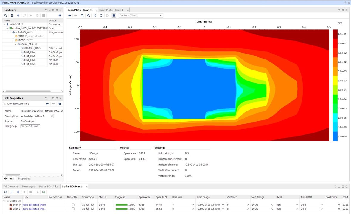
Got the ibert demo working. There were several typos in the demo .pdf that were preventing the build. I have found this to be a common issue with the Alinx docs. They modify a document to be used with a similar, but different, board. and end up with "cut-n-paste" type errors. In this instance the document had some code for a board with 4 SFP cages, and some for a board with 2. Prevented creation of a bit stream! Once I figured this out and changed to 2 cages throughout the code a bit stream built.
Setup with cable running between transceiver 0 and 1:

Link 0:
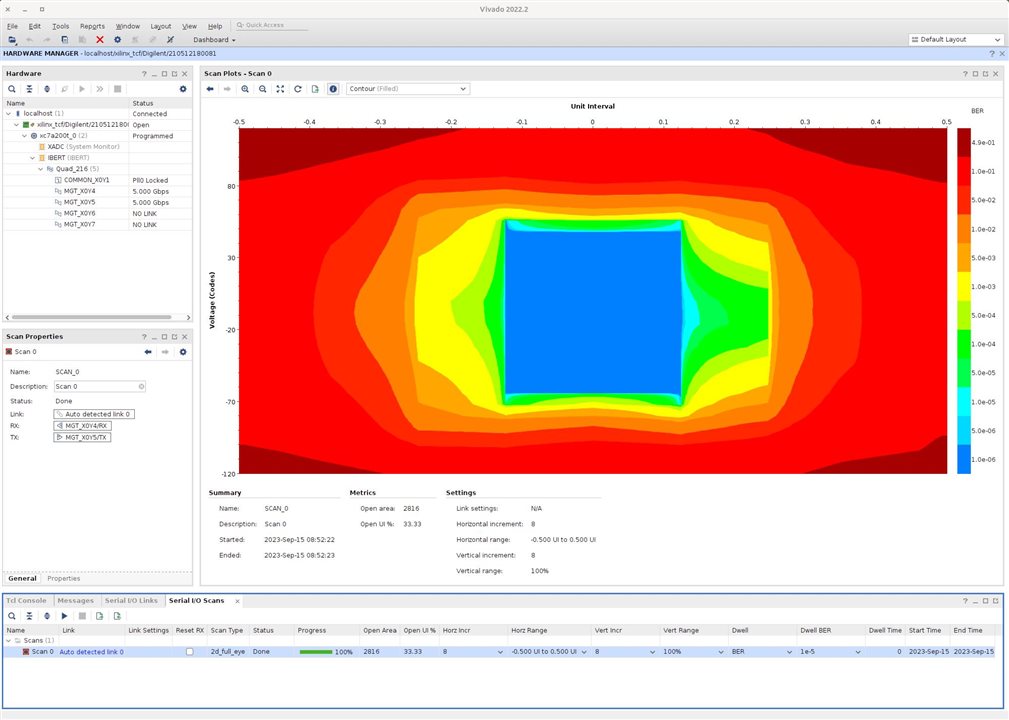
Link 1:
No idea why they look so different. I assume they show xfer between transceiver 0 to 1, and 1 to 0.
Another issue is that this demo only shows how to setup a dedicated test connected thru the JTAG. No info about using the SFP transceivers in a product... I have some R&D work ahead of me!
============================================================
September 20, 2023
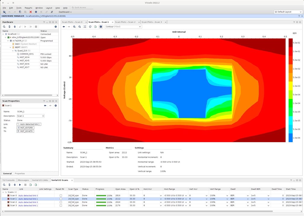
I swapped fiber cable ends and reran ibert:
Link 0:
Link 1:
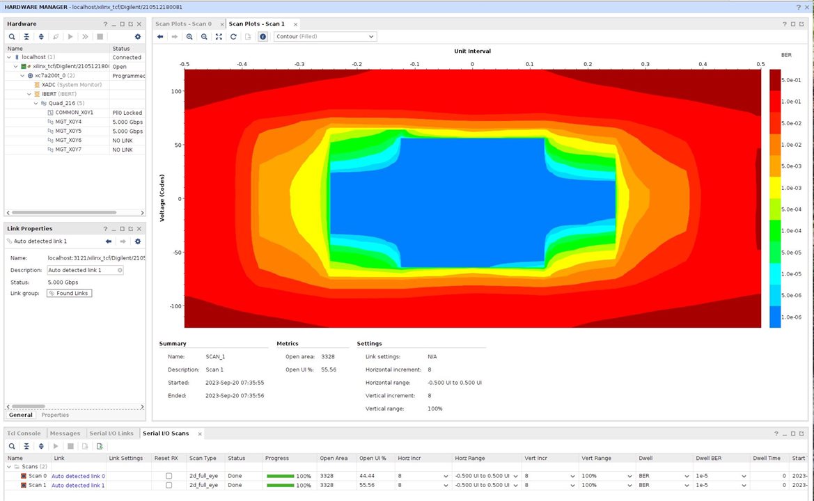
They are much more symmetrical now...
I'm currently planning on using Aurora for the fiber connection IP:
https://docs.xilinx.com/r/en-US/pg046-aurora-8b10b/Aurora-8B/10B-v11.1-LogiCORE-IP-Product-Guide
It has me very confused at this point!
============================================================
December 19, 2023
Winter started closing in and I realized not only that I had things to do like cut/split/stack 6 cords of wood, but to catch up on all the summer land maintenance I'd been neglecting.So now I'm caught up and ready to proceed again. The board I plan to use for the ADCs, AX7202, dropped in price from $520 to $343, so I figured I should grab one while the grabbing was good:

Still waiting on the DropBox link to get the documents and FPGA example code that goes with it. Their customer service is not the best...
They list a "GTP Fiber Optic Data Communication Experiment" among the examples, hopefully it will help with my current problems.
---------------------------------------------------------------------------------------
I've visited that post "Transceiver Tech Tips - Tuning Your Transceiver" only to find the videos unavailable. I tracked them down:
Tech Tip Transceiver Tools 101 Intro to IBERT
Tech Tip Transceiver Tools 102: We have an IBERT bit stream, now what?
Tech Tip Transceiver Tools 103: Now that we are running, what are all these adjustments?
Tech Tip Transceiver Tools 104: Getting More Margin
============================================================
January 2, 2024
It took several more attempts to get the demo documents, they sent me a DropBox link for the incorrect board, which I didn't notice till I had downloaded all 4GByte of it. Then after complaining about this SEVERAL TIMES they sent a link for what I guess is the correct stuff, labeled "夹“AX7202_EN_Refer to AX7102”. I knew then that I was in for trouble. The board I am using (AX7202) is a new design, purchased directly via their PayPal account. It is similar to the AX7102, except that it has a series 200 FPGA, while the AX7102 uses a series 100 part. Each demo comes with a pre-built .bit file that can be loaded and run. At least this was true with my last 2 Alinx boards. Unfortunately the pre-builts that came with this board are compiled for the 100 series, so I get this when attempting to program the part:
===
set_property PROBES.FILE {} [get_hw_devices xc7a200t_0]
set_property FULL_PROBES.FILE {} [get_hw_devices xc7a200t_0]
set_property PROGRAM.FILE {/home/Xilinx/AX7202/24_time/rtc_test/rtc_test/rtc_test.runs/impl_1/top.bit} [get_hw_devices xc7a200t_0]
program_hw_devices [get_hw_devices xc7a200t_0]
ERROR: [Labtools 27-3303] Incorrect bitstream assigned to device. Bitfile is incompatible for this device.
                          Bitstream was generated for device xc7a100t and target device is xc7a200t.
And added to that they were built with Vivado 2017, so I have to go thru the 2017 to 2022.2 conversion issues...
I have the rotating LED test converted, built and working, so I guess there's hope:
set_property PROGRAM.FILE {/home/Xilinx/AX7202/01_led_test/led_test/led_test/led_test.runs/impl_1/led_test.bit} [get_hw_devices xc7a200t_0]
current_hw_device [get_hw_devices xc7a200t_0]
refresh_hw_device -update_hw_probes false [lindex [get_hw_devices xc7a200t_0] 0]
INFO: [Labtools 27-1434] Device xc7a200t (JTAG device index = 0) is programmed with a design that has no supported debug core(s) in it.
set_property PROBES.FILE {} [get_hw_devices xc7a200t_0]
set_property FULL_PROBES.FILE {} [get_hw_devices xc7a200t_0]
set_property PROGRAM.FILE {/home/Xilinx/AX7202/01_led_test/led_test/led_test/led_test.runs/impl_1/led_test.bit} [get_hw_devices xc7a200t_0]
program_hw_devices [get_hw_devices xc7a200t_0]
INFO: [Labtools 27-3164] End of startup status: HIGH
program_hw_devices: Time (s): cpu = 00:00:08 ; elapsed = 00:00:08 . Memory (MB): peak = 9135.711 ; gain = 0.000 ; free physical = 13437 ; free virtual = 38595
refresh_hw_device [lindex [get_hw_devices xc7a200t_0] 0]
The manual claims the FPGA is an: ARTIX-7 series 200T AC7200-2FGG484I
But no such part exists on the Xilinx website, or in the Vivado list of available FPGA models. It appears that the old AX7102 used a XC7A100T SOM module which uses a Xilinx XC7A100T-2FGG484I. They evidently forgot to properly edit the part number when upgrading the manual. I had already glued the heatsink on my board, but looking closely at the Alinx site shows it to really be an FBG484:

which is in the Vivado list. Using it worked properly.
Successfully built and ran a switch test and RS-232 UART test.
Successfully built and ran the VGA test. This is the first test that required IP upgrade, which can be gnarly, but it worked OK:
============================================================
January 3, 2024
SUCCESS!!!
I have successfully built and loaded "32_gtp_test", which:
The test data is generated by the FPGA itself and transmit by GTP to the first optical fiber port. Then, through the fiber loop to the second fiber port, the GTP receives data for verification.
Determining when an error occurs (or not) is done with the ILA. As I have no experience using the ILA I need to fall back and study that.
The probe stores error counts in bytes 8-11:

assign probe0[103:72] = error_packet_cnt_o;

15141312 11100908    0706050403020100      < bit fields

0000b20    00000100   04468220a0a0a0a0      < samples
0000de0    00000100   10f74ae0cccccccc


00001d0    0001afa00  1bd6f4b000000000      < after pulling optic cable


00009a0    0001c6d00  2620604088888888      < samples taken after replacing cable
0000010    0001c6d00  2f25b980f4f4f4f4
0000d50    0001c6d00  389cf3e0c3c3c3c3
For some reason 100h errors have occurred before the first capture is run,,, Note that after replacing the optic cable the error count no longer increases.
============================================================
January 4, 2024
Turns out I was off by 1 byte parsing the ILA probe values, it starts out with 1 error, probably just a startup issue:
$ cat ../iladata.csv | ./dumpprobe
input-> 0,0,0,0000fd00000001012c04dbf0d9d9d9d9
00000001 1 - 12c04dbf 314592703
 ...
 input-> 4095,4095,0,0000ac00000001012c04dcf088888888
00000001 1 - 12c04dcf 314592719

# pull the fiber
$ cat ../iladata.csv | ./dumpprobe
input-> 0,0,0,0000870000329f0151ef04f063636363
0000329f 12959 - 151ef04f 354349135
 ...
The values above are errors in hex, errors in decimal, count in hex, count in decimal.
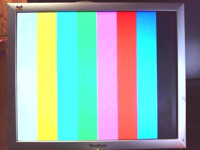
I went on to refactor the fiber/VGA demo for the new board/FPGA.

This demo records an image with the camera on the board expansion slot, sends it out the 1st optic transceiver, reads it back from the 2nd transceiver, and displays on the VGA monitor. This is using the 30 meter optic cable.
I think the next step is to get the ILA based fiber optic test running on the main (AX7A200) board. I was floundering with fiber optics on that board in part because it didn't come with any such demo to use as a starting point. If I can get the ILA demo working there its just a matter of a lot of perspiration!
============================================================
January 6, 2024
Got the ILA based fiber optic test running on the main (AX7A200) board. Tried following the directions in the accompanying PDF file, but that created "something entirely different".
So I tried the binary from the AX7202, this didn't work. Examined the schematics and .xdc files. Noticed that tx_disable was on different pins. Copied the AX7202 ILA test source to the AX7A200 directory, changed the set_property values for the 2 tx_disable signals and it works!
I will next modify the fiber optic test to just echo whatever comes in port 1 to port 2. Will run this on the AX7202 and the current fiber test on the AX7A200. Connect ports between the 2 boards so that data goes out the AX7A200, enters the AX7202, is resent back out the 2nd port to the AX7A200. The fiber test program shouldn't notice that the signal loops thru the second board (as opposed to simply looping thru the fiber). This will pretty much validate optic fiber data xfer between the 2 boards!
============================================================
February 6, 2024

I decided to build the echo program from scratch, shown above. Pulling one of the optic cables usually causes errors to occur, but not always! I *think its the test program freezing for some reason ... but when it does start accumulating errors, replacing the cable always makes them stop. Not gonna' waste a lot of time trying to figure that out...
============================================================
February 21, 2024
Turns out that this board was a poor choice for PCIe + SFP transceivers. Without getting into too much detail, it requires an FPGA with multiple transceiver QUADs as PCIe requires complete control of its QUAD(s) and wont easily share them with aurora. I need to step up to a Kintex 7 FPGA, but can't afford the $2995 license... Hoping to find a vendor of a suitable board that comes with a voucher for a chip specific license.
For those interested in the gory details, see:
============================================================
February 26, 2024
I threw the switch on a Kintex7 based board. Starting a fresh blog to support it:
Software Defined Transceiver Redux