


Introduction:
After learning about various things that can be done on Arty S7-50, I think I am now ready to put all my learnings together in one project.
In this blog, I will try to implement a basic image processing algorithm (blurring an image) on the Arty S7 board and then transfer the blurred image over uartlite to my PC.
There are some challenges in it:
1. Images can't be directly loaded onto the board. So, I will have to initalize a 2D array containing the RGB values of each pixel as its elements and then operate on it.
2. The blurred image will also be stored in an array. This image array will have over one lac element and I will have to send it over uartlite. So, I will have to make sure that there is sufficient time between sending bytes so that the PC doesn't miss any data.
Block Design:
The image will be a large file. It can't be loaded into the 128K BRAM. I will need to include the SDRAM in my design. I have already done it in my previous blog. The block design is shown below: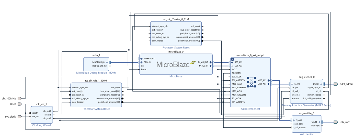
Now, I added the LEDs to my design to be able to keep track of what's happening on my board. To add the LEDs, just drag and drop "4 LEDs" from the "board" tab. Regenerate the layout. The final block design will look like this: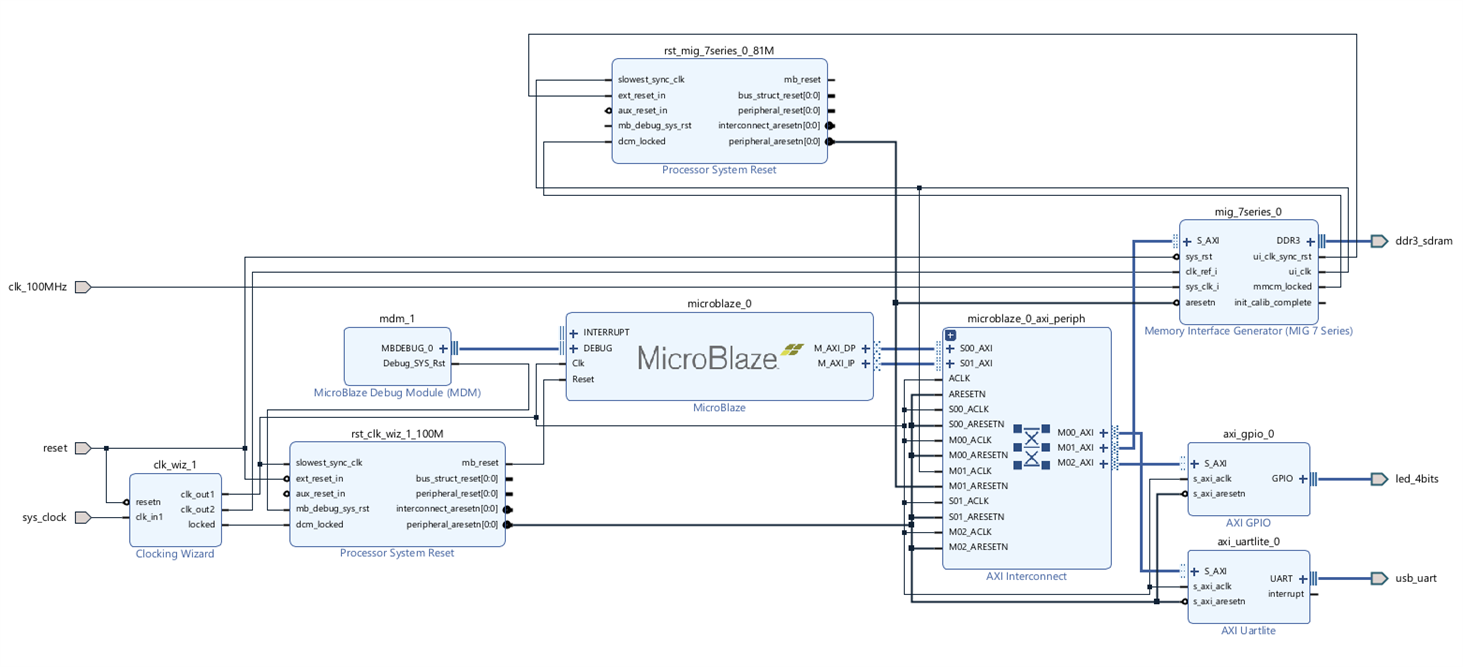
Now, run connection automation, validate the block design, generate bitstream, export it as hardware and launch it on vitis.
Converting image to text:
We can't directly load the image on the board. So, first we will write the pixel values (RGB values) to a file and then copy paste these values to our Vitis project and initialize a 2D array with this data.
I will be using the following image to test my code. The image's dimension is (400x400):
I wrote a python code to get the pixel data and write it to a file.
image_to_text.py:
from PIL import Image

#Open the image and load the pixels
img = Image.open(r"C:/Users/Chinmay/Desktop/image/image.jpg")
pixels = img.load()

#Open a file to write pixel values to
file = open("C:/Users/Chinmay/Desktop/image/image.txt", "w")

#Get width and height of the image
(WIDTH, HEIGHT) = img.size
print(WIDTH, HEIGHT)

#Write pixel vavlues to the file
for row in range(HEIGHT):
	for column in range(WIDTH):
		file.write("{" + str(pixels[column, row][0]) + "," + str(pixels[column, row][1]) + "," + str(pixels[column, row][2]) + "},\n")

#Close the file
file.close()
The generated file will look something like this:
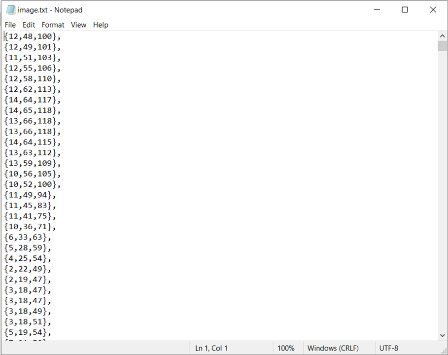
The file will have 160000 rows representing each pixel with 3 columns each (RGB values).
The box blur algorithm:
There are various algorithms to blur an image like the Gaussian blur, Box blur etc. I will be using the box blur approach.
A box blur is a filter in which each pixel in the resulting image has a value equal to the average of the elements of a square matrix formed by keeping the original pixel in its center. It is illustrated in the below figure: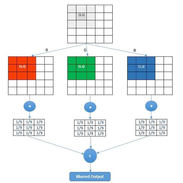
The extent of blur depends on the size of this matrix. I am using a (5x5) matrix.
Writing code in Vitis:
Now, we can start writing our algorithm. Open Vitis and create an empty C application project. The project "src" folder will have three files along with "platform.h", "platform_config.h" and "platform.c" which can be copied from the "Hello World" template project:
1. main.c - Contains the main code and algorithm.
2. image.h - Declares a global variable to store the IMAGE array.
3. image.c - Initializes the IMAGE array.
image.h: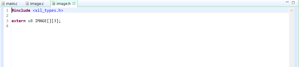
Each element of the 2D array can have '255' as maximum value (8 bits). The IMAGE variable is declared as extern, so that all other files can access it.
image.c: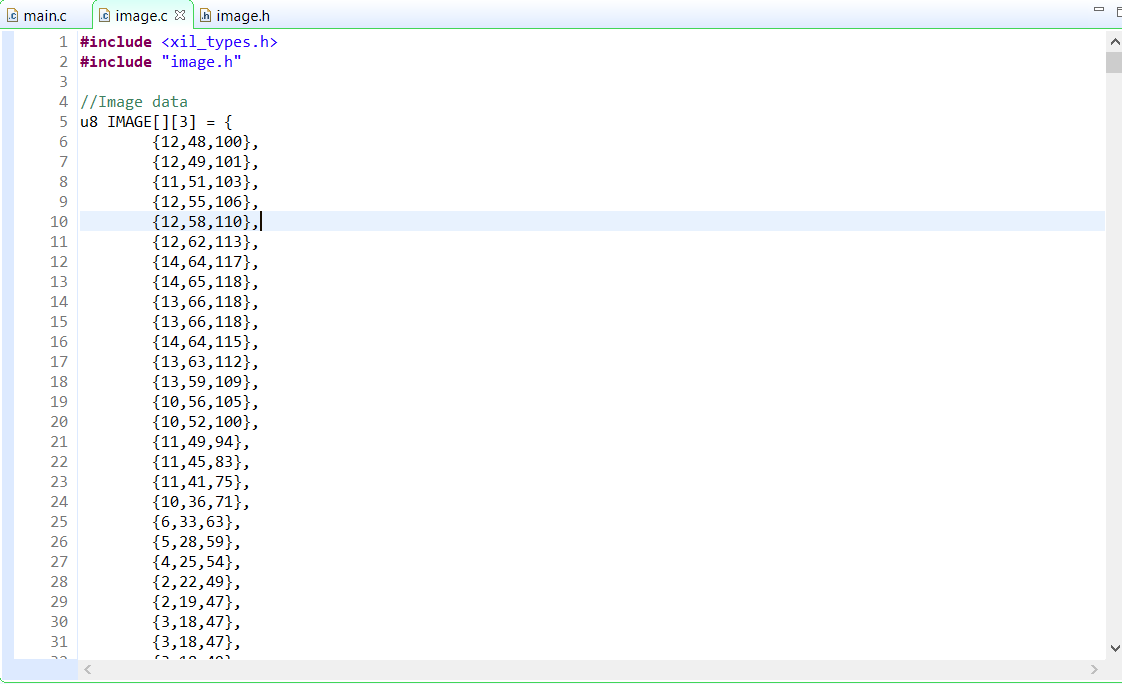
This file contains the image data in an array. This image data is copied from the text file that was earlier generated using the python code.
main.c:
This file contains the main code that will implement the box blur algorithm and send the blurred image over uartlite.
Code:
#include <sleep.h>
#include <xil_types.h>
#include <xparameters.h>
#include <xgpio.h>
#include <xuartlite.h>
#include "platform.h"
#include "image.h"

#define LED_CHANNEL 1

//Gpio and Uart Instances
XGpio Gpio;
XUartLite uart;

int main() {
	init_platform();

	//Width, Height and total number of pixels
	u16 WIDTH = 400;
	u16 HEIGHT = 400;
	u32 PIXELS = WIDTH*HEIGHT;

	//Initialize the Gpio and set data direction for the led channel as output
	XGpio_Initialize(&Gpio, XPAR_GPIO_0_DEVICE_ID);
	XGpio_SetDataDirection(&Gpio, LED_CHANNEL, 0b0000);

	//First LED is turned on to depict start of program
	XGpio_DiscreteWrite(&Gpio, LED_CHANNEL, 0b1000);

	//Array to store the blur image
	static u8 BLUR_IMAGE[160000][3];

	//Algorithm to get the blurred image
	for(u16 i=0; i<HEIGHT; i++) {
		for(u16 j=0; j<WIDTH; j++) {

			//Coordinates of the (5x5) pixel matrix
			u16 start_corner_row = (0>i-2) ? 0 : i-2;
			u16 start_corner_col = (0>j-2) ? 0 : j-2;
			u16 end_corner_row = (HEIGHT-1<i+2) ? HEIGHT-1 : i+2;
			u16 end_corner_col = (WIDTH-1<j+2) ? WIDTH-1 : j+2;

			//Represents the three R,G,B values of a pixel
			u16 blur_R = 0;
			u16 blur_G = 0;
			u16 blur_B = 0;

			//Adding all the values of R,G,B layers of the pixels in the pixel matrix
			for(u16 m=start_corner_row; m<=end_corner_row; m++) {
				for(u16 n=start_corner_col; n<=end_corner_col; n++) {
					u32 pixel_ind = m*WIDTH + n;
					blur_R += IMAGE[pixel_ind][0];
					blur_G += IMAGE[pixel_ind][1];
					blur_B += IMAGE[pixel_ind][2];
				}
			}

			//Calculating average
			blur_R /= 25;
			blur_G /= 25;
			blur_B /= 25;

			//Assigning to the BLUR_IMAGE variable
			BLUR_IMAGE[i*WIDTH + j][0] = blur_R & 0xFF;
			BLUR_IMAGE[i*WIDTH + j][1] = blur_G & 0xFF;
			BLUR_IMAGE[i*WIDTH + j][2] = blur_B & 0xFF;

		}
	}

	//Second LED is turned on to depict end of image processing
	XGpio_DiscreteWrite(&Gpio, LED_CHANNEL, 0b1100);

	//Represents 50% of total pixel count
	u32 percent_50 = PIXELS/2;

	//Initialize the UART
	XUartLite_Initialize(&uart, XPAR_UARTLITE_0_DEVICE_ID);

	//Sending the blurred pixels 3 bytes at a time
	for(u32 i=0; i<PIXELS; i++) {
		XUartLite_Send(&uart, BLUR_IMAGE[i], 3);

		//Third LED is turned on to depict that 50% of pixels have been transmitted
		if(i>percent_50)
			XGpio_DiscreteWrite(&Gpio, LED_CHANNEL, 0b1110);

		//Delay of 50 us to let the receiver capture the data correctly
		usleep(50);
	}

	//Fourth LED is turned on to depict that all the pixels have been sent
	XGpio_DiscreteWrite(&Gpio, LED_CHANNEL, 0b1111);

	cleanup_platform();
	return 0;
}
- The code can be divided into three sections: 1. Controlling the LEDs as status LEDs, 2. Code to implement the box blur algorithm, 3. Send the blurred image over uartlite.
- The first LED will turn on at the starting of the code.
- The second LED will turn on when the image processing completes i.e. the BLUR_IMAGE is ready to be sent.
- The third LED will turn on when half of the pixels are sent.
- The fourth LED will turn on when all the pixels are sent.
- If you are not familiar with sending data over uartlite, you can visit this blog.
- If you are not familiar with Gpio, you can visit this blog.
- I have inserted a delay of 50 usec after sending every 3 bytes. I tried with no delay and lesser delays i.e. 10usec or 20usec, the python code wasn't able to capture all the data. With 50 usec delay, its working fine.
- The BLUR_IMAGE array needs to be declared as static. A static array behaves in C/C++ code as a memory does in RTL. For more information, click here.
Now, after writing the code, you can build it. Then program the FPGA and run it as "Launch Hardware".
Capturing the Blurred Image:
Now, since we have blurred the image and ready to send it over uartlite, we should write the code to receive it on the PC. We will use the "pyserial" package in python to receive the image data. After receiving the data, it will be written into a file.
You can visit this blog for more information about the code.
uart_recv.py:
import serial

#Image dimensions and total number of pixels in it
WIDTH = 400
HEIGHT = 400
PIXELS = WIDTH*HEIGHT
IMAGE = []

#Setting the serial port
ser = serial.Serial()
ser.baudrate = 9600
ser.port = 'COM7'
ser.timeout = None
print(ser)

#Opening the serial port
ser.open()
print(ser.isOpen())

print("Receiving...")

#Getting the pixel data one byte at a time
for i in range(PIXELS):
	R = ser.read(1)
	G = ser.read(1)
	B = ser.read(1)

	IMAGE.append([R,G,B])

print("Received!")

#Closing the serial port
ser.close()

#Converting the pixel data into int
for pixel in IMAGE:
	pixel[0] = int.from_bytes(pixel[0], 'big', signed=False)
	pixel[1] = int.from_bytes(pixel[1], 'big', signed=False)
	pixel[2] = int.from_bytes(pixel[2], 'big', signed=False)

#Open the file to write to
file = open("C:/Users/Chinmay/Desktop/image/blur_image.txt", "w")

#Write the pixel data to the file
for pixel in IMAGE:
	file.write("{" + str(pixel[0]) + "," + str(pixel[1]) + "," + str(pixel[2]) + "},\n")

print("Written to File!")

#Close the file
file.close()
The file will look like this:
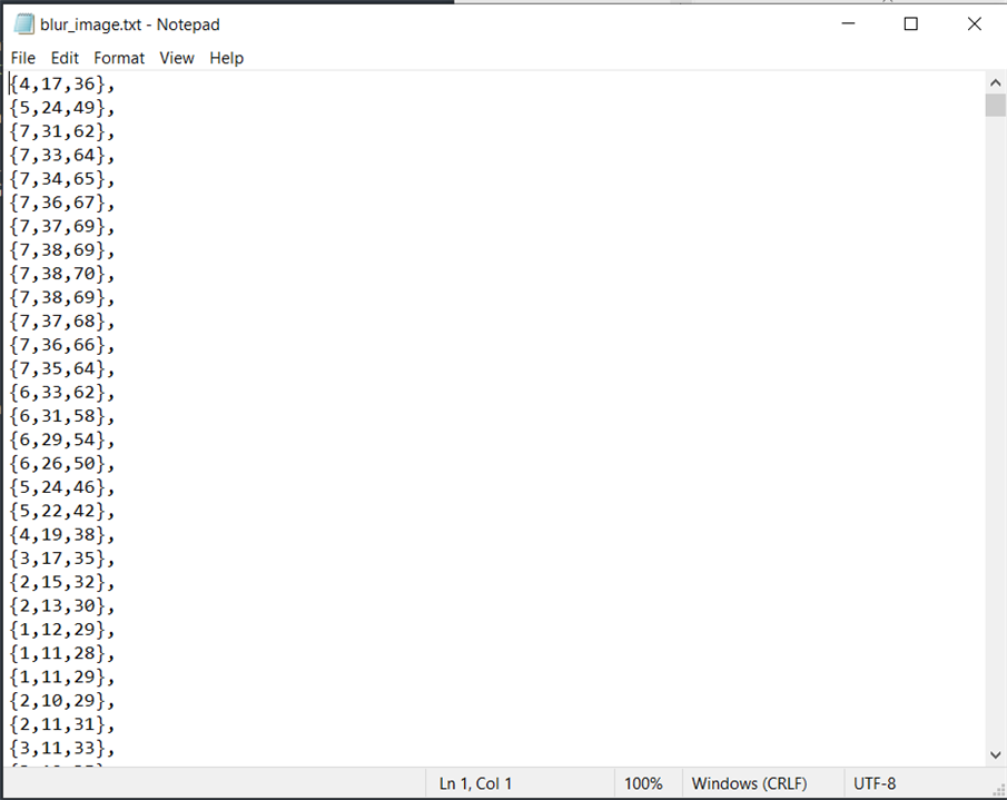
This code will receive (160000*3) bytes of data and then store it in a file.
This python code must be run before the second LED on the board turns on after programming it. You can even run it while the FPGA is being programmed. But make sure that no other program is using the port to which your board is connected i.e. Close the terminal on Vitis if its connected.
Converting text to image:
After receiving the blurred image over uart and writing it to a file, we can convert this pixel data into a image.
txt_to_image.py:
from PIL import Image

#Image Dimensions
HEIGHT = 400
WIDTH = 400

#Open the txt file to read image data and store it line by line in a list
file = open(r"C:/Users/Chinmay/Desktop/image/blur_image.txt");
lines = file.readlines()
lines = [x.strip('\n') for x in lines]

#Create an image and load the pixels
img = Image.new('RGB', (WIDTH, HEIGHT), (0,0,0))
pixels = img.load()

print(HEIGHT, WIDTH)

#Pixel Coordinates
x = 0
y = 0

#Assigning data from txt file to each pixel in the image
for line in lines:
	R,G,B = line[1:-2].split(',')

	R = int(R)
	G = int(G)
	B = int(B)

	pixels[x,y] = (R,G,B)

	x += 1
	if (x == WIDTH):
		y += 1
		x = 0

#Save the image
img.save("blur_image.jpg")
So, the received image look like this:

Run the Project:
- First create the pixel array txt file using image_to_txt.py code.
- Now, copy this array from the txt file and paste it in image.c in vitis.
- Now, launch the code on hardware from Vitis.
- While the board is being programmed, run the uart_recv.py code to start looking for data on the COM7 (in my case its COM7, yours can be different) port and save it to a file after receiving it.
- Now, from the blurred image data received and saved in a file, generate an image using txt_to_image.py code and save it.
A video of the board in action is shown below at 10x speed:
Comparison:
The original image and the blurred image are shown below for comparison:
Conclusion:
It took around 4 minutes to blur this image on the board and around 9 minutes to transmit it over uart. That seems to be quite a time to do some simple image processing like blurring. But, we should remember that we haven't used all the resources available on the board in our design. Moreover, it could have been faster if we would have used a faster processor IP.
Top Comments
-

javagoza
-
Cancel
-
Vote Up
+1
Vote Down
-
-
Sign in to reply
-
More
-
Cancel
-

cbohra00627
in reply to javagoza
-
Cancel
-
Vote Up
0
Vote Down
-
-
Sign in to reply
-
More
-
Cancel
Comment-

cbohra00627
in reply to javagoza
-
Cancel
-
Vote Up
0
Vote Down
-
-
Sign in to reply
-
More
-
Cancel
Children