


Introduction:
In my previous blog, I learned how to use the XADC block in my design. I am thinking of using the XADC alongwith the IR sensor that I used in that blog in my Image Processing project.
I will use this IR sensor to toggle between various box sizes for the box blur algorithm.
Block Design:
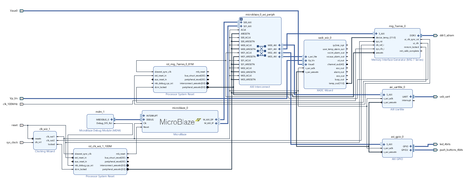
I had created a MicroBlaze based microcontroller with SDRAM in one of my previous blogs. The link is here. I will be using this block design as a base and modify it according to my needs. The block design is shown below: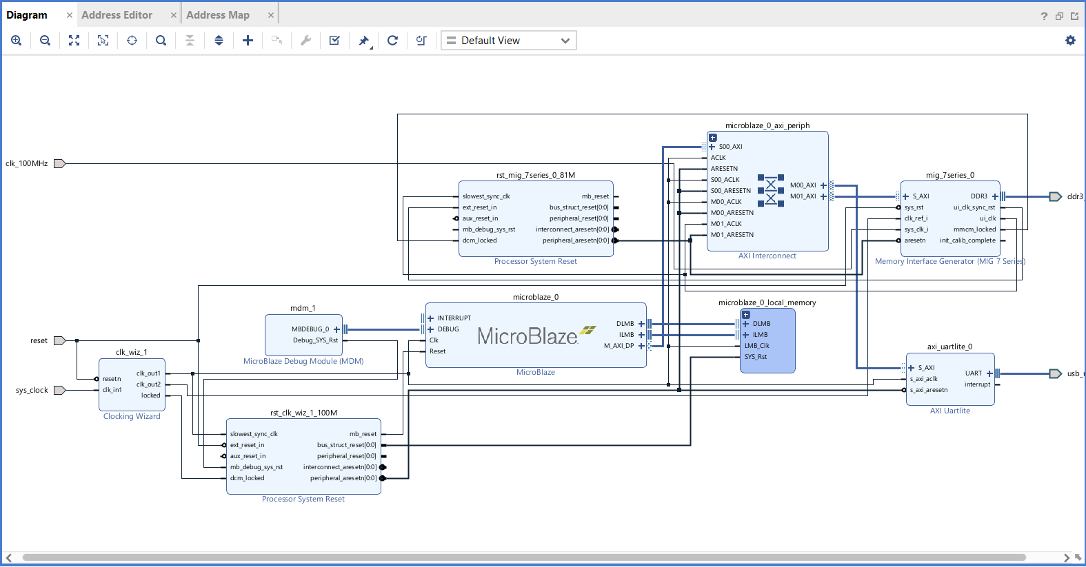
In this design, I need to add an XADC block, 4 leds and push buttons.
- From the "Board" tab, drag and drop "4 LEDs" and "4 Push Buttons".
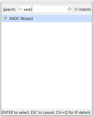
- Click on "Add IP", search for "XADC Wizard" and insert it.
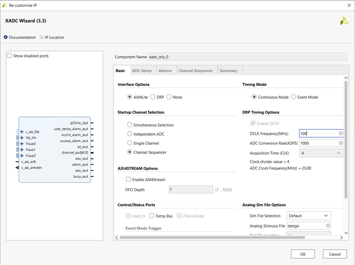
- Double click on the XADC Block to customize it.
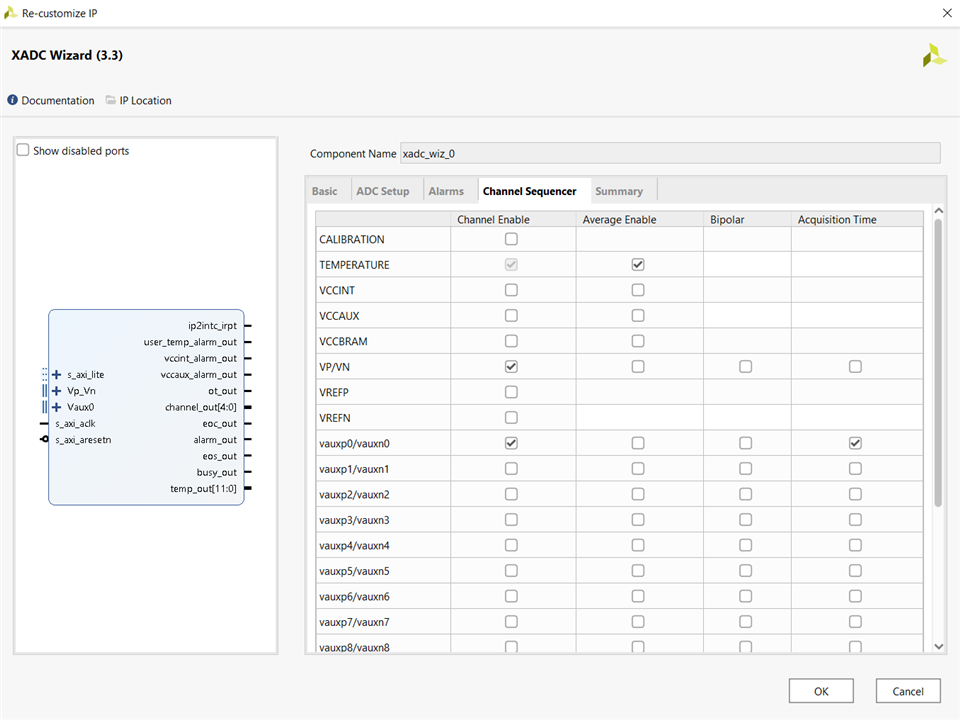
- In the customize wizard, select "AXI4Lite" for "Interface Options" and select "Channel Sequencer" for "Startup Channel Selection".
- In the Channel Sequencer tab, enable "vauxp0/vaux0n" as shown below.
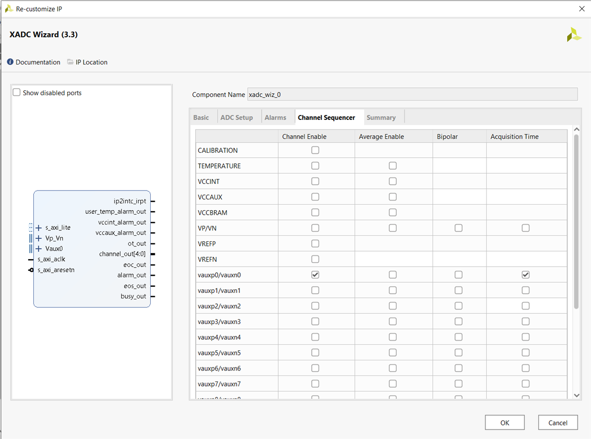
- Click on "OK".
- Run connection automation by selecting all automation and regenerate the layout.
- Right click on the "Vp_Vn" port of the XADC block, click on "Create Interface Port". Click on "OK".
- Similarly, click on the "Vaux0" port of the XADC block, click on "Create Interface Port". Click on "OK".
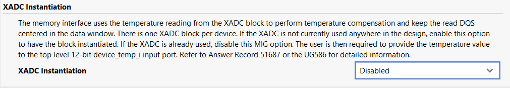
- Now, if you would try to implement this design, it will throw some error saying "XADC over-utilized in top design". The problem is that when we customized the MIG for SDRAM in the other blog, we enabled the "XADC Instantiation" to monitor temperature. And then we added one XADC block again in our design. This means that the design is using two XADCs but we have only one XADC available on the board.
- To resolve this issue, we have to disable the "XADC Instatiation" in the MIG wizard and feed it with the temperature from the XADC block that we inserted.
- Double click on the MIG block to customize it. Keep clicking on "Next" till we reach "XADC Instantiation" option, disable it. Keep clicking on "NEXT". Then click on generate.
- Now, double click on XADC block to customize it. Enable "temp bus". This will create a temperature port in the XADC block.

- Now, if you would see in the "Channel Sequencer" tab, the "Temperature" will be automatically enabled.
- Now, connect the "temp_out" port of XADC to the "device_temp_i" port of the MIG. Regenerate the layout. The final block design will look like this:
- Validate the design. Save it. Create HDL wrapper.
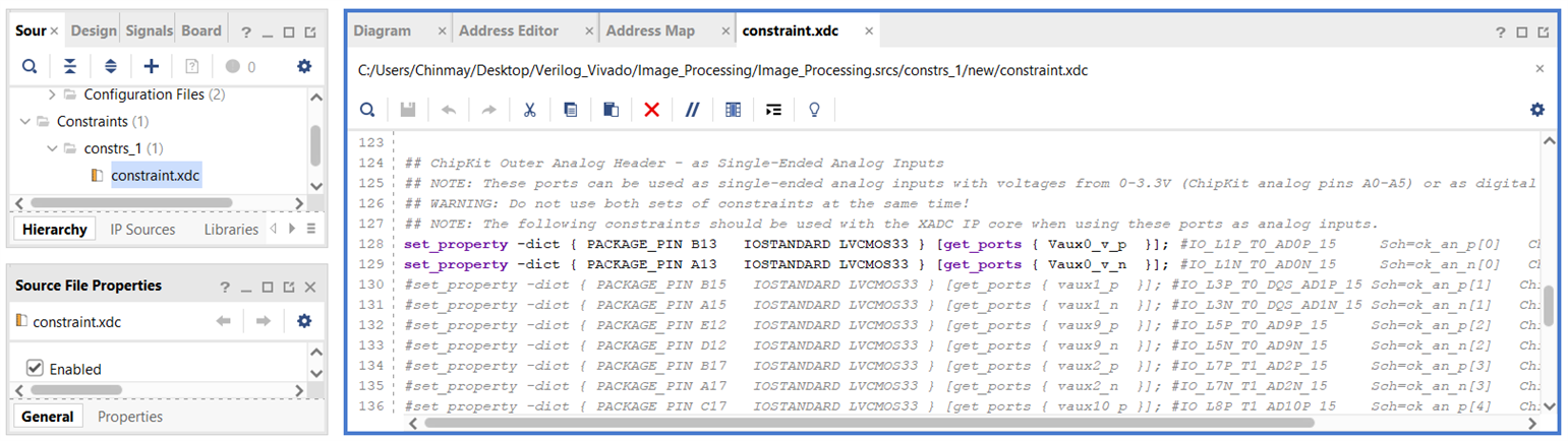
- Now, we will have to include the constraint file for to assign proper IOStandard for the analog pins.
- Download the constraint file from this link.
- Copy the contents and paste in a new constraint file created in the project.
- Uncomment the lines and change port names as shown below:
- Run Synthesis, Implementation and Generate Bitstream.
- Export the hardware to XSA file.
Working on Vitis:
Since, we have prepared the hardware, we can now start working on the code. I will be using the same algorithm that I used in my previous blog with minor modifications. The steps to launch the program would be the same.
Launched Vitis, created an empty C application by the xsa file that we created as platform. Copied all the files inside the "src" folder of the Image Processing project to the "src" folder of the current project.
Now, we need to slightly modify the "main.c" file. We need to include the section in which the the sensor will continuously monitor the value from the IR sensor from the A0 port. If it detects any IR signal, it will increase the blur box size by 1 and reflect the box size by turning on the corresponding LEDs. It will keep monitoring the A0 port and keep updating the value of box size until any of the push buttons is pressed. It will then continue with the algorithm.
Code:#include <sleep.h>
#include <xil_types.h>
#include <xparameters.h>
#include <xgpio.h>
#include <xuartlite.h>
#include <xsysmon.h>
#include "platform.h"
#include "image.h"
#define LED_CHANNEL 1
#define BUTTON_CHANNEL 2
//Gpio and Uart Instances
XGpio Gpio;
XUartLite uart;
//XADC and XADC Config Instances
XSysMon xadc;
XSysMon_Config *xadc_config;
int main() {
init_platform();
//LED mask
u8 LED = 0;
u8 BUTTON = 0;
//Width, Height and total number of pixels
u16 WIDTH = 400;
u16 HEIGHT = 400;
u32 PIXELS = WIDTH*HEIGHT;
u8 box_size = 1; //Blur Box Matrix Size (default: 1), 1: (3x3), 2: (5x5), 3: (7x7)
static u8 BLUR_IMAGE[160000][3]; //Array to store the blur image
//Initialize the Gpio and set data direction for the led channel as output and for button channel as input
XGpio_Initialize(&Gpio, XPAR_GPIO_0_DEVICE_ID);
XGpio_SetDataDirection(&Gpio, LED_CHANNEL, 0b0000);
XGpio_SetDataDirection(&Gpio, BUTTON_CHANNEL, 0b1111);
//Load default configuration and initialize the XADC
xadc_config = XSysMon_LookupConfig(XPAR_SYSMON_0_DEVICE_ID);
XSysMon_CfgInitialize(&xadc, xadc_config, xadc_config->BaseAddress);
//All LEDs on for ten msecond to depict start of the program
XGpio_DiscreteWrite(&Gpio, LED_CHANNEL, 0b1111);
usleep(10000);
/********************************Blur Box Size***********************************************/
//Initial and default value of box size is 1
box_size = 1;
XGpio_DiscreteWrite(&Gpio, LED_CHANNEL, 0b1000);
//Variable to store IR receiver data
u16 sensor_value;
//The loop will keep updating the box size till any of the push button is pressed
while(!XGpio_DiscreteRead(&Gpio, BUTTON_CHANNEL)) {
//Getting the IR sensor data
sensor_value = XSysMon_GetAdcData(&xadc, XSM_CH_AUX_MIN);
//If the data read is less than 1000, that means a button on the remote is pressed and the box size needs to be incremented
if(sensor_value < 1000) {
box_size += 1;
if(box_size > 3)
box_size = 1;
}
//Selecting the LED mask according to the box size
switch(box_size) {
case 1: LED = 0b1000;
break;
case 2: LED = 0b1100;
break;
case 3: LED = 0b1110;
break;
default: LED = 0b1000;
}
//Turning on LEDs according to the LED mask
XGpio_DiscreteWrite(&Gpio, LED_CHANNEL, LED);
//Delay of 2 mseconds between consecutive iterations
usleep(2000);
}
//Turning on all the LEDs for ten msecond depict the box size is selected
XGpio_DiscreteWrite(&Gpio, LED_CHANNEL, 0b1111);
usleep(10000);
/************************************End*****************************************************/
/**********************************Box Blur Algorithm****************************************/
//Matrix Size
u8 mat_size = 2*box_size + 1;
//Total elements in the matrix
u8 tot_ele = mat_size*mat_size;
//First LED is turned on to depict start of the box blur algorithm
XGpio_DiscreteWrite(&Gpio, LED_CHANNEL, 0b1000);
//Algorithm to get the blurred image
for(u16 i=0; i<HEIGHT; i++) {
for(u16 j=0; j<WIDTH; j++) {
//Coordinates of the pixel matrix
u16 start_corner_row = (0>i-box_size) ? 0 : i-box_size;
u16 start_corner_col = (0>j-box_size) ? 0 : j-box_size;
u16 end_corner_row = (HEIGHT-1<i+box_size) ? HEIGHT-1 : i+box_size;
u16 end_corner_col = (WIDTH-1<j+box_size) ? WIDTH-1 : j+box_size;
//Represents the three R,G,B values of a pixel
u16 blur_R = 0;
u16 blur_G = 0;
u16 blur_B = 0;
//Adding all the values of R,G,B layers of the pixels in the pixel matrix
for(u16 m=start_corner_row; m<=end_corner_row; m++) {
for(u16 n=start_corner_col; n<=end_corner_col; n++) {
u32 pixel_ind = m*WIDTH + n;
blur_R += IMAGE[pixel_ind][0];
blur_G += IMAGE[pixel_ind][1];
blur_B += IMAGE[pixel_ind][2];
}
}
//Calculating average
blur_R /= tot_ele;
blur_G /= tot_ele;
blur_B /= tot_ele;
//Assigning to the BLUR_IMAGE variable
BLUR_IMAGE[i*WIDTH + j][0] = blur_R & 0xFF;
BLUR_IMAGE[i*WIDTH + j][1] = blur_G & 0xFF;
BLUR_IMAGE[i*WIDTH + j][2] = blur_B & 0xFF;
}
}
//Second LED is turned on to depict end of image processing
XGpio_DiscreteWrite(&Gpio, LED_CHANNEL, 0b1100);
/**************************************End**********************************************/
/******************************Send blurred image over uartlite*************************/
//Represents 50% of total pixel count
u32 percent_50 = PIXELS/2;
//Initialize the UART
XUartLite_Initialize(&uart, XPAR_UARTLITE_0_DEVICE_ID);
//Sending the blurred pixels 3 bytes at a time
for(u32 i=0; i<PIXELS; i++) {
XUartLite_Send(&uart, BLUR_IMAGE[i], 3);
//Third LED is turned on to depict that 50% of pixels have been transmitted
if(i>percent_50)
XGpio_DiscreteWrite(&Gpio, LED_CHANNEL, 0b1110);
//Delay of 50 us to let the receiver capture the data correctly
usleep(50);
}
//Fourth LED is turned on to depict that all the pixels have been sent
XGpio_DiscreteWrite(&Gpio, LED_CHANNEL, 0b1111);
/**************************************End**********************************************/
cleanup_platform();
return 0;
}
Program the FPGA. Run the code as "Launch Hardware".
Using a TV remote, I set the box size to be 3 (i.e. box matrix of (7x7))
A video of the board in action is shown below in 10x speed. (I connected my IR sensor on the board at wrong pins by mistake and it burnt. I checked, it was still working, not perfectly but still it could catch some of the IR signals. I connected it the right way (left terminal to A0, middle to Ground, right to 3V3) and then recorded the video)
After receiving the image through uartlite, I converted the received data into image and the result is shown below:

To compare it with another box size, the blurred image generated with a box size of 2 (i.e. blur box matrix size - (5x5)) is shown below:

Conclusion:
The code takes more time if I keep increasing the box size. For box size = 1, it took around 4 mins to blur the image and for box size = 3, it took around 7 mins to blur the image. It takes over 10 mins to transmit the image over UART. Well, the time seems too much but we should remember we are not using the board to its full potential. We can use better processor IP to work faster.