element14 Community
element14 Community
    Register Log In
  • Site
  • Search
  • Log In Register
  • Community Hub
    Community Hub
    • What's New on element14
    • Feedback and Support
    • Benefits of Membership
    • Personal Blogs
    • Members Area
    • Achievement Levels
  • Learn
    Learn
    • Ask an Expert
    • eBooks
    • element14 presents
    • Learning Center
    • Tech Spotlight
    • STEM Academy
    • Webinars, Training and Events
    • Learning Groups
  • Technologies
    Technologies
    • 3D Printing
    • FPGA
    • Industrial Automation
    • Internet of Things
    • Power & Energy
    • Sensors
    • Technology Groups
  • Challenges & Projects
    Challenges & Projects
    • Design Challenges
    • element14 presents Projects
    • Project14
    • Arduino Projects
    • Raspberry Pi Projects
    • Project Groups
  • Products
    Products
    • Arduino
    • Avnet Boards Community
    • Dev Tools
    • Manufacturers
    • Multicomp Pro
    • Product Groups
    • Raspberry Pi
    • RoadTests & Reviews
  • Store
    Store
    • Visit Your Store
    • Choose another store...
      • Europe
      •  Austria (German)
      •  Belgium (Dutch, French)
      •  Bulgaria (Bulgarian)
      •  Czech Republic (Czech)
      •  Denmark (Danish)
      •  Estonia (Estonian)
      •  Finland (Finnish)
      •  France (French)
      •  Germany (German)
      •  Hungary (Hungarian)
      •  Ireland
      •  Israel
      •  Italy (Italian)
      •  Latvia (Latvian)
      •  
      •  Lithuania (Lithuanian)
      •  Netherlands (Dutch)
      •  Norway (Norwegian)
      •  Poland (Polish)
      •  Portugal (Portuguese)
      •  Romania (Romanian)
      •  Russia (Russian)
      •  Slovakia (Slovak)
      •  Slovenia (Slovenian)
      •  Spain (Spanish)
      •  Sweden (Swedish)
      •  Switzerland(German, French)
      •  Turkey (Turkish)
      •  United Kingdom
      • Asia Pacific
      •  Australia
      •  China
      •  Hong Kong
      •  India
      •  Korea (Korean)
      •  Malaysia
      •  New Zealand
      •  Philippines
      •  Singapore
      •  Taiwan
      •  Thailand (Thai)
      • Americas
      •  Brazil (Portuguese)
      •  Canada
      •  Mexico (Spanish)
      •  United States
      Can't find the country/region you're looking for? Visit our export site or find a local distributor.
  • Translate
  • Profile
  • Settings
FPGA
  • Technologies
  • More
FPGA
Blog Learning AMD Zynq: a project to generate a set of PWM signals. 3 - add GATE signal and demodulation clock
  • Blog
  • Forum
  • Documents
  • Quiz
  • Events
  • Polls
  • Files
  • Members
  • Mentions
  • Sub-Groups
  • Tags
  • More
  • Cancel
  • New
Join FPGA to participate - click to join for free!
  • Share
  • More
  • Cancel
Group Actions
  • Group RSS
  • More
  • Cancel
Engagement
  • Author Author: Jan Cumps
  • Date Created: 6 May 2023 5:08 PM Date Created
  • Views 1972 views
  • Likes 12 likes
  • Comments 23 comments
  • pynq-z2
  • amdzynqultrasoundpulse
  • zynq
  • fpga
  • vivado
  • vhdl
  • pynq
  • spartan
Related
Recommended

Learning AMD Zynq: a project to generate a set of PWM signals. 3 - add GATE signal and demodulation clock

Jan Cumps
Jan Cumps
6 May 2023
Learning AMD Zynq: a project to generate a set of PWM signals. 3 - add GATE signal and demodulation clock

Continuation of  Learning AMD Zynq: a project to generate a set of PWM signals. 2 - add overall control block, delay and pulse signal .

 yepe has a goal to create a set of signals for an ultrasone pulse generator.

image

Status after Post 2

In Post 2, we ended up with a PRF, PWM(n) and PULSE working. GATE wasn't implemented.
image

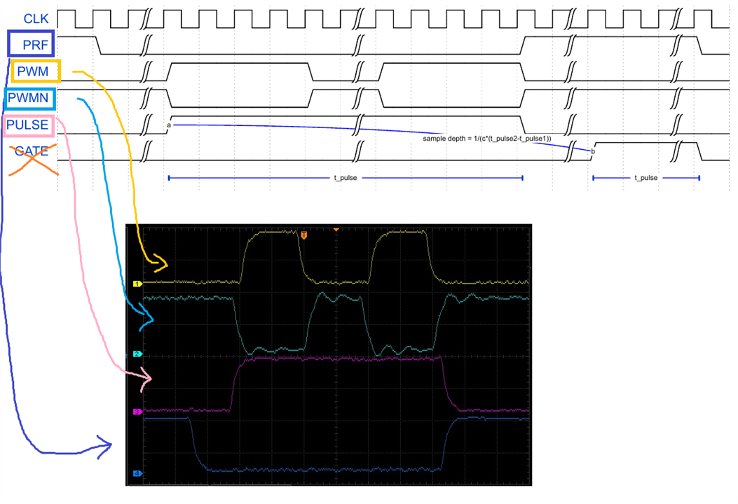
Part of the GATE code was there already. The state machine had states for the delay between the pulse train and gate signal, and for the gate signal itself. 
image

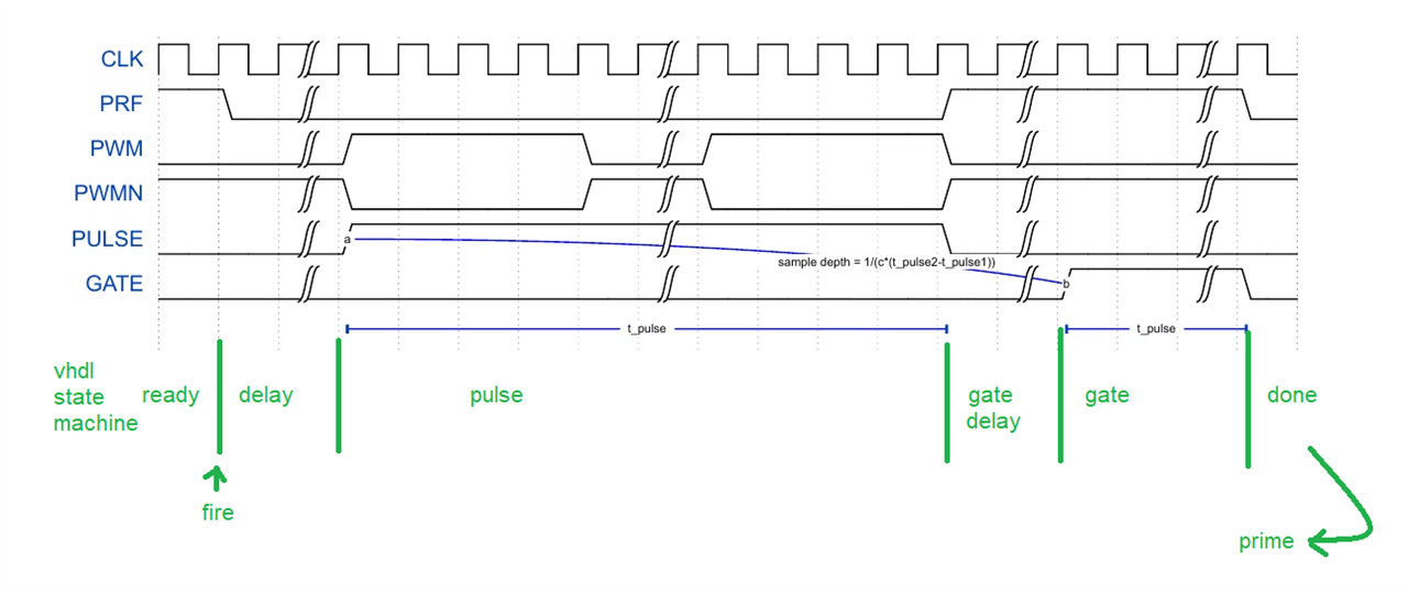
But there was no logic to get the required delay, or to handle that gate signal. Luckily, this is easy.

To get the gate delay, we'll add an extra register to the board design:
image

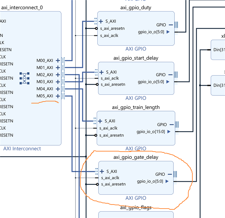
Don't forget to generate an address for it, using the address editor.

The Jupyter notebook will use that register to set the delay:

gate_delay_address = ol.ip_dict['axi_gpio_gate_delay']['phys_addr']
gate_delay_register = MMIO(gate_delay_address, RANGE) 
# Write 0x00 to the tri-state register at offset 0x4 to configure the IO as outputs.
gate_delay_register.write(0x4, 0x0) # Write 0x0 to location 0x4; Set tri-state to output

# ...

def gatedelay(gatedelay):
    gate_delay_register.write(0x0, gatedelay);
    
# ...

def gatedelay(gatedelay):band(2)
startdelay(20)
trainlength(98)
gatedelay(20)
prime()
fire()

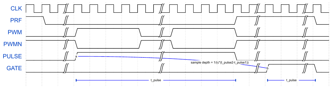
The signal controller state machine will handle both the delay and the uptime of the GATE. The uptime is identical to the pulse train length, so we need no register to set it separately:

    component signal_controller is
    ---
        port (
            ---
            start_delay_i : in   std_logic_vector (start_delay_resolution - 1 downto 0);   -- delay before the pulse train.
            train_length_i: in   std_logic_vector (train_length - 1 downto 0);             -- how many PWMs in a burst train.
            gate_delay_i  : in   std_logic_vector (gate_delay_resolution - 1 downto 0);    -- delay before gate signal.
            ---
        );
    end component;

---


entity signal_controller is
    --- 
    port (
    ---
        start_delay_i : in   std_logic_vector (start_delay_resolution - 1 downto 0);   -- delay before the pulse train.
        train_length_i: in   std_logic_vector (train_length - 1 downto 0);             -- how many PWMs in a burst train.
        gate_delay_i  : in   std_logic_vector (gate_delay_resolution - 1 downto 0);    -- delay before gate signal.
        ---
    );
end signal_controller;

architecture arch of signal_controller is
    ---


begin

                case State is
                
                ---

                    when gate_delay =>
                        leds_o <= (0 => '0', 1 => '0', 2 => '1', others => '0');
                        if counter >= to_integer(unsigned(gate_delay_i)) - 1 then
                            counter <= 0;
                            state <= gate;
                        end if;

                    when gate =>
                        leds_o <= (0 => '1', 1 => '0', 2 => '1', others => '0');
                        gate_o <= '1';
                        if counter = to_integer(unsigned(train_length_i)) - 1 then
                            counter <= 0;
                            state <= done;  -- todo implement
                        end if;
                    ---
                end case;

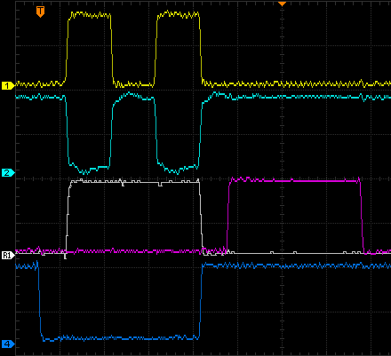
This is an example capture:

image

Demodulation Clock

An extra requirement is to have a 20 MHz output signal to serve as demodulation clock. The easiest way to generate that, is to add an extra clock output to the existing clocking wizard:
image

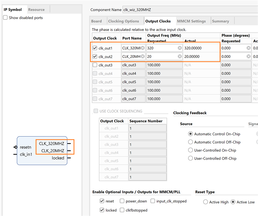
That extra output can be made external. Assign it to a PIN in the I/O window or constraints file.

image

Vivado 2022.1 project and Jupyter workbook
pwm_ultrasound_pulser_20230507.zip

link to all posts.

  • Sign in to reply

Top Comments

  • Jan Cumps
    Jan Cumps over 2 years ago +1
    The additional 20 MHz demodulation clock: The clock is not guaranteed in phase with the PWM. If that's a requirement, the state changes of the signal controller would have to be synced with the…
  • Jan Cumps
    Jan Cumps over 2 years ago in reply to dang74

    The port was just a few hours. I spent a day before that, to learn Microblaze :)

    The only thing that the software did on the Zynq, was to set registers. All signal logic was in VHDL.
    On the Spartan 7 I only had to port the "write to the registers" part from Python/Pynq on ARM/linux to C on microblaze bare metal. The VHDL ported without changes.

    • Cancel
    • Vote Up 0 Vote Down
    • Sign in to reply
    • More
    • Cancel
  • dang74
    dang74 over 2 years ago in reply to Jan Cumps

    Nice.  It didn't take very long to port over.

    • Cancel
    • Vote Up 0 Vote Down
    • Sign in to reply
    • More
    • Cancel
  • Jan Cumps
    Jan Cumps over 2 years ago in reply to dang74

    It works:

    You don't have permission to edit metadata of this video.
    Edit media
    x
    image
    Upload Preview
    image

    • Cancel
    • Vote Up 0 Vote Down
    • Sign in to reply
    • More
    • Cancel
  • Jan Cumps
    Jan Cumps over 2 years ago in reply to dang74

    > I mainly want to find the Arty

    Little white box Slight smile

    Here's where I got for the block diagram on that board: 

    image

    • Cancel
    • Vote Up 0 Vote Down
    • Sign in to reply
    • More
    • Cancel
  • dang74
    dang74 over 2 years ago in reply to Jan Cumps

    I mainly want to find the Arty so that I can get some practice in using Vivado.

    • Cancel
    • Vote Up 0 Vote Down
    • Sign in to reply
    • More
    • Cancel
>
element14 Community

element14 is the first online community specifically for engineers. Connect with your peers and get expert answers to your questions.

  • Members
  • Learn
  • Technologies
  • Challenges & Projects
  • Products
  • Store
  • About Us
  • Feedback & Support
  • FAQs
  • Terms of Use
  • Privacy Policy
  • Legal and Copyright Notices
  • Sitemap
  • Cookies

An Avnet Company © 2025 Premier Farnell Limited. All Rights Reserved.

Premier Farnell Ltd, registered in England and Wales (no 00876412), registered office: Farnell House, Forge Lane, Leeds LS12 2NE.

ICP 备案号 10220084.

Follow element14

  • X
  • Facebook
  • linkedin
  • YouTube