Continuation of Learning AMD Zynq: a project to generate a set of PWM signals. 2 - add overall control block, delay and pulse signal .
yepe has a goal to create a set of signals for an ultrasone pulse generator.

Status after Post 2
In Post 2, we ended up with a PRF, PWM(n) and PULSE working. GATE wasn't implemented.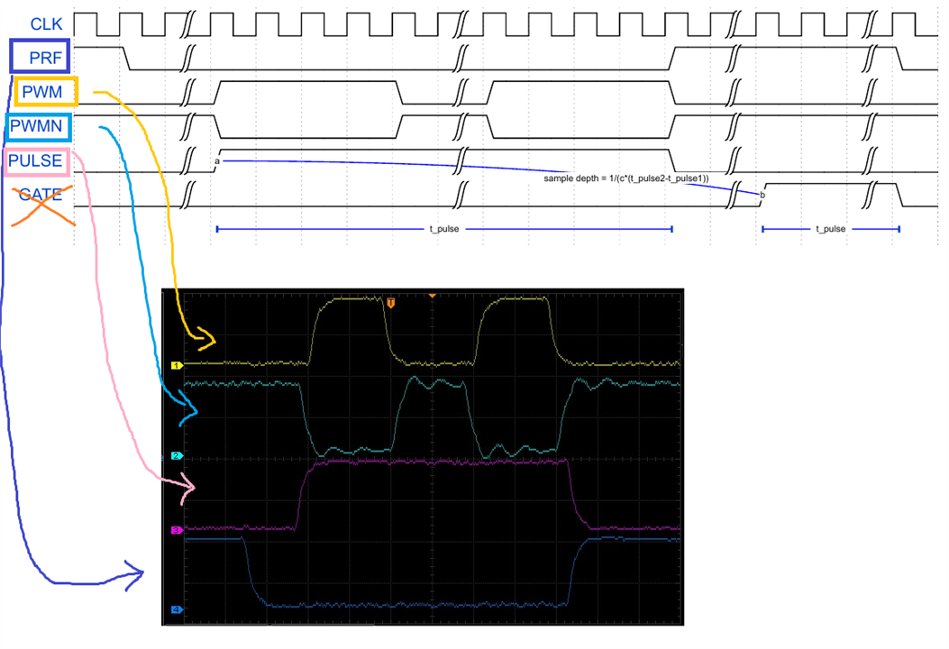
Part of the GATE code was there already. The state machine had states for the delay between the pulse train and gate signal, and for the gate signal itself. 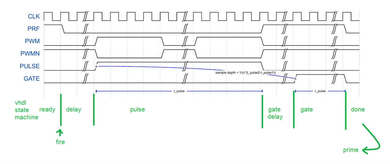
But there was no logic to get the required delay, or to handle that gate signal. Luckily, this is easy.
To get the gate delay, we'll add an extra register to the board design: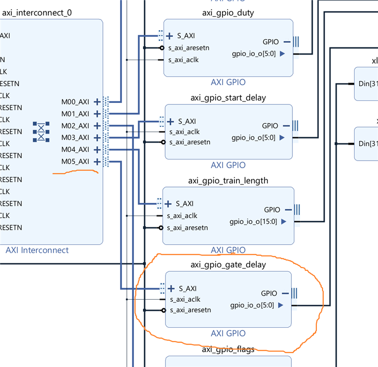
Don't forget to generate an address for it, using the address editor.
The Jupyter notebook will use that register to set the delay:
gate_delay_address = ol.ip_dict['axi_gpio_gate_delay']['phys_addr']
gate_delay_register = MMIO(gate_delay_address, RANGE)
# Write 0x00 to the tri-state register at offset 0x4 to configure the IO as outputs.
gate_delay_register.write(0x4, 0x0) # Write 0x0 to location 0x4; Set tri-state to output

# ...

def gatedelay(gatedelay):
    gate_delay_register.write(0x0, gatedelay);

# ...

def gatedelay(gatedelay):band(2)
startdelay(20)
trainlength(98)
gatedelay(20)
prime()
fire()
The signal controller state machine will handle both the delay and the uptime of the GATE. The uptime is identical to the pulse train length, so we need no register to set it separately:
    component signal_controller is
    ---
        port (
            ---
            start_delay_i : in   std_logic_vector (start_delay_resolution - 1 downto 0);   -- delay before the pulse train.
            train_length_i: in   std_logic_vector (train_length - 1 downto 0);             -- how many PWMs in a burst train.
            gate_delay_i  : in   std_logic_vector (gate_delay_resolution - 1 downto 0);    -- delay before gate signal.
            ---
        );
    end component;

---


entity signal_controller is
    ---
    port (
    ---
        start_delay_i : in   std_logic_vector (start_delay_resolution - 1 downto 0);   -- delay before the pulse train.
        train_length_i: in   std_logic_vector (train_length - 1 downto 0);             -- how many PWMs in a burst train.
        gate_delay_i  : in   std_logic_vector (gate_delay_resolution - 1 downto 0);    -- delay before gate signal.
        ---
    );
end signal_controller;

architecture arch of signal_controller is
    ---


begin

                case State is

                ---

                    when gate_delay =>
                        leds_o <= (0 => '0', 1 => '0', 2 => '1', others => '0');
                        if counter >= to_integer(unsigned(gate_delay_i)) - 1 then
                            counter <= 0;
                            state <= gate;
                        end if;

                    when gate =>
                        leds_o <= (0 => '1', 1 => '0', 2 => '1', others => '0');
                        gate_o <= '1';
                        if counter = to_integer(unsigned(train_length_i)) - 1 then
                            counter <= 0;
                            state <= done;  -- todo implement
                        end if;
                    ---
                end case;
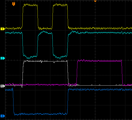
This is an example capture:
Demodulation Clock
An extra requirement is to have a 20 MHz output signal to serve as demodulation clock. The easiest way to generate that, is to add an extra clock output to the existing clocking wizard: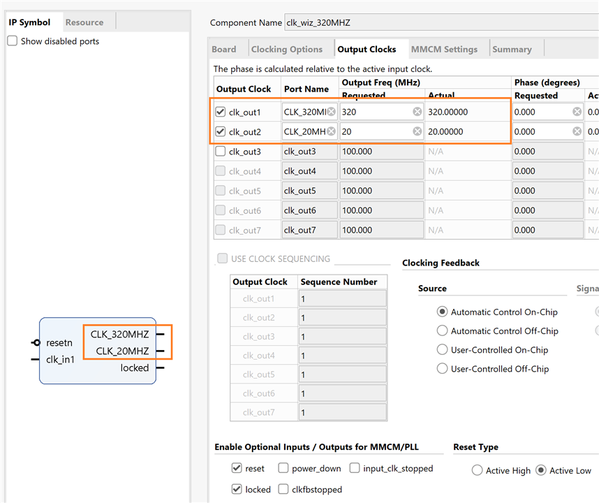
That extra output can be made external. Assign it to a PIN in the I/O window or constraints file.

Vivado 2022.1 project and Jupyter workbook
pwm_ultrasound_pulser_20230507.zip


Top Comments
-

dang74
-
Cancel
-
Vote Up
0
Vote Down
-
-
Sign in to reply
-
More
-
Cancel
-

Jan Cumps
in reply to dang74
-
Cancel
-
Vote Up
0
Vote Down
-
-
Sign in to reply
-
More
-
Cancel
-

dang74
in reply to Jan Cumps
-
Cancel
-
Vote Up
0
Vote Down
-
-
Sign in to reply
-
More
-
Cancel
-

Jan Cumps
in reply to dang74
-
Cancel
-
Vote Up
0
Vote Down
-
-
Sign in to reply
-
More
-
Cancel
-

dang74
in reply to Jan Cumps
-
Cancel
-
Vote Up
0
Vote Down
-
-
Sign in to reply
-
More
-
Cancel
-

Jan Cumps
in reply to dang74
-
Cancel
-
Vote Up
0
Vote Down
-
-
Sign in to reply
-
More
-
Cancel
Comment-

Jan Cumps
in reply to dang74
-
Cancel
-
Vote Up
0
Vote Down
-
-
Sign in to reply
-
More
-
Cancel
Children