element14 Community
element14 Community
    Register Log In
  • Site
  • Search
  • Log In Register
  • Community Hub
    Community Hub
    • What's New on element14
    • Feedback and Support
    • Benefits of Membership
    • Personal Blogs
    • Members Area
    • Achievement Levels
  • Learn
    Learn
    • Ask an Expert
    • eBooks
    • element14 presents
    • Learning Center
    • Tech Spotlight
    • STEM Academy
    • Webinars, Training and Events
    • Learning Groups
  • Technologies
    Technologies
    • 3D Printing
    • FPGA
    • Industrial Automation
    • Internet of Things
    • Power & Energy
    • Sensors
    • Technology Groups
  • Challenges & Projects
    Challenges & Projects
    • Design Challenges
    • element14 presents Projects
    • Project14
    • Arduino Projects
    • Raspberry Pi Projects
    • Project Groups
  • Products
    Products
    • Arduino
    • Avnet & Tria Boards Community
    • Dev Tools
    • Manufacturers
    • Multicomp Pro
    • Product Groups
    • Raspberry Pi
    • RoadTests & Reviews
  • About Us
  • Store
    Store
    • Visit Your Store
    • Choose another store...
      • Europe
      •  Austria (German)
      •  Belgium (Dutch, French)
      •  Bulgaria (Bulgarian)
      •  Czech Republic (Czech)
      •  Denmark (Danish)
      •  Estonia (Estonian)
      •  Finland (Finnish)
      •  France (French)
      •  Germany (German)
      •  Hungary (Hungarian)
      •  Ireland
      •  Israel
      •  Italy (Italian)
      •  Latvia (Latvian)
      •  
      •  Lithuania (Lithuanian)
      •  Netherlands (Dutch)
      •  Norway (Norwegian)
      •  Poland (Polish)
      •  Portugal (Portuguese)
      •  Romania (Romanian)
      •  Russia (Russian)
      •  Slovakia (Slovak)
      •  Slovenia (Slovenian)
      •  Spain (Spanish)
      •  Sweden (Swedish)
      •  Switzerland(German, French)
      •  Turkey (Turkish)
      •  United Kingdom
      • Asia Pacific
      •  Australia
      •  China
      •  Hong Kong
      •  India
      •  Korea (Korean)
      •  Malaysia
      •  New Zealand
      •  Philippines
      •  Singapore
      •  Taiwan
      •  Thailand (Thai)
      • Americas
      •  Brazil (Portuguese)
      •  Canada
      •  Mexico (Spanish)
      •  United States
      Can't find the country/region you're looking for? Visit our export site or find a local distributor.
  • Translate
  • Profile
  • Settings
FPGA
  • Technologies
  • More
FPGA
Blog OrangeCrab Gaming Console - Part 1
  • Blog
  • Forum
  • Documents
  • Quiz
  • Events
  • Polls
  • Files
  • Members
  • Mentions
  • Sub-Groups
  • Tags
  • More
  • Cancel
  • New
Join FPGA to participate - click to join for free!
  • Share
  • More
  • Cancel
Group Actions
  • Group RSS
  • More
  • Cancel
Engagement
  • Author Author: dang74
  • Date Created: 7 Nov 2022 2:46 AM Date Created
  • Views 14167 views
  • Likes 10 likes
  • Comments 10 comments
Related
Recommended

OrangeCrab Gaming Console - Part 1

dang74
dang74
7 Nov 2022

Introduction

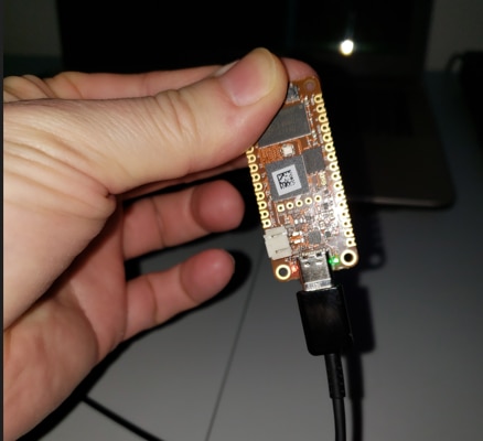
One of the advantages of membership in the Element14 community is the opportunity to evaluate brand new products and technologies.  Back in 2021 during the summer of FPGAs I was lucky enough to be selected to road test the OrangeCrab.  The OrangeCrab is a development board in the feather format that features an ECP5 FPGA from Lattice.

The main features of the OrangeCrab are:

  • ECP5 FPGA with 25k LUT's
  • 128MB DDR
  • 128Mb QSPI FLASH
  • Micro USB; full speed 12Mbps
  • Micro SD slot
  • SAR ADC

image

One interesting facet of the OrangeCrab is that it was designed to be used with an open source tool chain built around the YOSYS compiler and nextpnr placement and router tool.

Although packaged in a tiny form factor the OrangeCrab packs a lot of punch.  As of late I've been dabbling in FPGA arcade emulation and video generation and I was hoping to use the OrangeCrab as a platform to explore this hobby further.

Picking up Where I left Off

As I get older I marvel at how quickly time flies.  I had developed HDL code for a retro style tile based video generator.  I intended to feature this design in the RoadTest.  It's crazy to think that more than a year has passed between then and the time of this writing.

Back then I hit a road block in the form of a cryptic compiler error.

It's worth noting that I was using the Windows version of the open source FPGA tools.  My fellow RoadTesters had pointed out that the Windows tools weren't as up to date as the Linux version.  So this time around I activated WSL and installed the Debian distribution of Linux.

Since so much time had passed I had forgotten how to use the open source tools.  The excellent RoadTests from skruglewicz and dramoz served me well as reference material and I was up and running in no time at all.

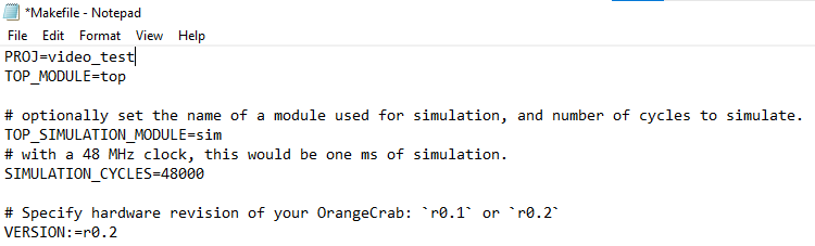
The one thing I did remember though, was that the pwm_rainbow verilog example was set up to handle hierarchical designs.  I made a copy of this folder and renamed it to video_test.  In the new folder I erased all of the files inherited from the pwm_rainbow example with the exception of the Makefile.  I then proceeded to copy over the design files I developed last year.

Next I edited the Makefile, changing the first line from PROJ=pwm_rainbow to PROJ=video_test.

image

Since I'll be using the open source FPGA tools it was necessary to set its path assignment.  This was done by typing the following:

export PATH=$PATH:/mnt/c/FPGA_tools/fpga-toolchain/bin/

Now it was time to compile the design.

To compile the design I navigated to the video_test folder and typed make.

image

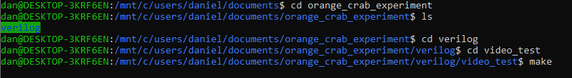
A year ago when I tried this I was hit with an insurmountable compiler error... so I found myself sitting in suspense while waiting for the compilation results.

I was finally presented with the following results:

image

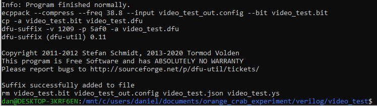
Program finished normally!

Suffix successfully added to file!

This sounds good, and sure enough when I checked the folder contents the DFU file that is required to program the FPGA was indeed generated.

Programming the OrangeCrab

So far I have not been able to use Debian to configure the OrangeCrab.  This is not a problem because I still have the Windows version of the tools.  Inconveniently enough though the Windows tools are on another lap top so this required copying the design folder over.

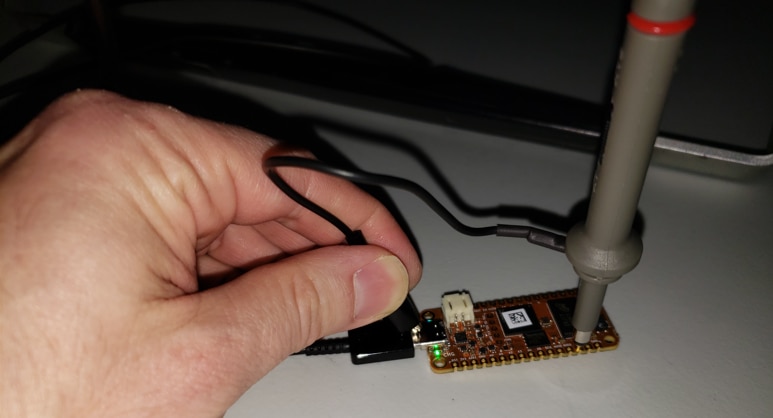
To program the board I navigated to the video_test design folder using command prompt. Then I connected the OrangeCrab to the PC.  As I did this I made sure to press down on its push button.  This causes the OrangeCrab to enter boot loader mode.

image

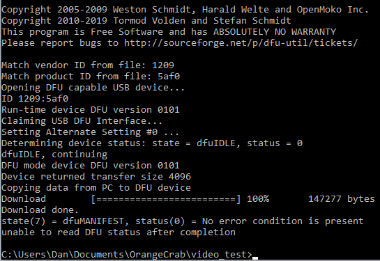
Finally to start the programming  process I typed make dfu

image

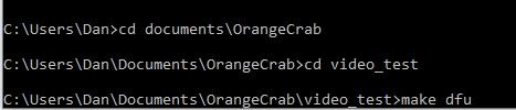
The programming completed successfully with no errors being reported.

image 

But how do we really know programming was successful?

Is there anything we can test?

My application produces video using VGA's 640 x 480 pixel resolution.  So it should be possible to probe the horizontal synch pulse and verify its timing.

image

image

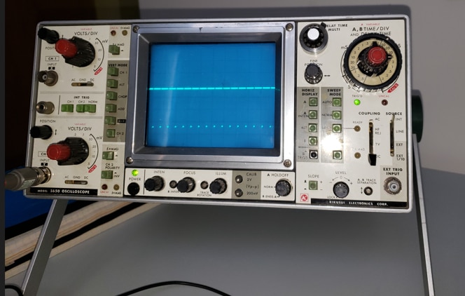
This certainly looks like HSYNCH.  So far so good.

The HSYNCH frequency for the 640 x 480 resolution is 31.469 kHz.  It follows then that its period should be 31.78us.

image

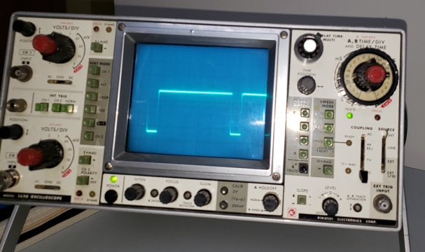
When we zoom in we see that the signal repeats roughly every 6 1/2 divisions on the oscilloscope's 5us/DIV setting.  This works out to 32.5us which is very close to the 31.78us we were expecting.

So yeah, I think we just verified that HSYNCH is being produced.  This is an encouraging sign.

 PCB

The successful compile inspired me to design a mother board for the OrangeCrab.   Actually I had already designed a mother board last year.  The original design shown below included a site for the OrangeCrab and a site to receive an Arduino.

image

The OrangeCrab would sit on top of the mother board while the Arduino would sit underneath.  Additional cards, say for instance a joystick controller, would then be installed underneath the Arduino.  In general as more functions were introduced their respective cards would be added to the bottom of the stack.  Before too long we'd have the tower of Babel on our hands.

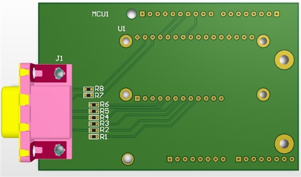
I abandoned this idea and went for a new approach.  The new board is shown below.

image

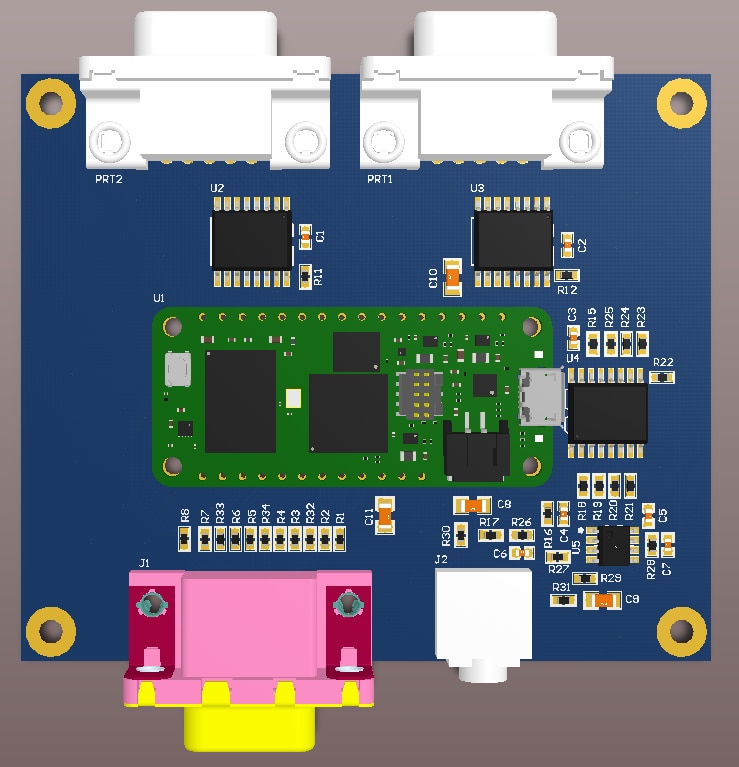
This time around there are no stacks.  The mother board will only receive the OrangeCrab.  Of course this also means that video generation will not be under Arduino control.  Instead I will use this as an opportunity to learn how to develop for the RISCV processor which will reside within the FPGA itself.

The motherboard is designed to support 3 main functions:

  • Video Generation
  • Game Controller Support
  • Sound

Video Generation

Video generation is implemented using resistor DACs.  Each RGB component signal has 3 resistors which provides us with 9 bits to set colour with.  In theory this allows for 512 different colour combinations.

Game Pad Controller

The board will support 2x Sega Genesis 3 button game controllers.  Since the OrangeCrab has a limited number of I/O the ports are accessed through I/O expanders.  The OrangeCrab will read the I/O expanders using I2C.

Sound

Sound generation also utilizes an I/O expander which the OrangeCrab accesses through I2C.  The I/O expander will be used to generate 8 square wave audio channels.  The 8 audio channels are divided in such a way that 4 are routed to each speaker.  The I2C clock rate is only 400kbps which will cause inaccuracies in the audio frequency.  It will be interesting to see if this will be perceptible to the ear.

Next Step

Currently I am doing last minute checks on the PCB design.  Once I am reasonably confident that there are no major errors I'll place an order for the boards.  It's not always easy to revisit a project after a year but I am happy this one was resurrected.  I can't wait to receive the boards.

  • Sign in to reply

Top Comments

  • dougw
    dougw over 3 years ago +1
    Looks good. I'll be interested to follow your progress.
  • baldengineer
    baldengineer over 3 years ago +1
    I bought an OrangeCrab a couple of years ago, but I have not done anything with it. I'm interested to see how your project goes. It renews my interest in doing something with the board / FPGA.
  • dang74
    dang74 over 2 years ago in reply to jc2048

    It was definitely nice to have a little break-through, but the challenges in taking the open source route continue.  Prior to adding a RISCV SoC I was thinking of using a 6502 core to help test the basic graphics functions.  To troubleshoot the 6502 core that I found I ended up leaving the world of open source to use vendor tools.  Just this weekend I was re-targeting the design to an Intel/Altera Dev board so that I could use the Signal Tap II embedded logic analyzer to help with the debug.  Right now my graphic's system supports sprites, one scrolling tile based background and one foreground layer for status and score.  The foreground layer doesn't scroll.  I want to add a RISCV processor and use the SD card slot or QSPI FLASH to store games.

    • Cancel
    • Vote Up 0 Vote Down
    • Sign in to reply
    • More
    • Cancel
  • jc2048
    jc2048 over 2 years ago

    Interesting project. It's good to see you're past the initial problems and now able to work with the board. The ECP5 device is a nice part - certainly a step up from the XP2 part I've been using (I considered competing in the roadtest, but didn't think I could manage the toolchain side of it - there's a lot to be said for just plugging-in a board and clicking a couple of buttons in an IDE to program it).

    Looking forward to seeing the game side of things developing. Is it essentially a sprite engine that you're developing/implementing?

    • Cancel
    • Vote Up 0 Vote Down
    • Sign in to reply
    • More
    • Cancel
  • dang74
    dang74 over 3 years ago in reply to shabaz

    Thanks.  Initially I was going to use a multichannel serial DAC for sound but I didn't have a specific part selected... that's when the idea of using the I/O expander entered my mind.  It was to save time researching a part, creating its schematic symbol and footprint.  So not only is necessity the mother of invention sometimes laziness is too, lol.

    • Cancel
    • Vote Up 0 Vote Down
    • Sign in to reply
    • More
    • Cancel
  • dang74
    dang74 over 3 years ago in reply to shabaz

    Initially I was disappointed that it was Verilog focused because I've always used VHDL.  In fact I learned Verilog just for the Road Test.  So it was good in a sense that it gave me the incentive to finally learn the language, and hey I get another thing to put on the resume. Wink 

    • Cancel
    • Vote Up 0 Vote Down
    • Sign in to reply
    • More
    • Cancel
  • shabaz
    shabaz over 3 years ago

    The I/O expander as a sound generator sounds very cool and unique! There are also low-cost SPI I/O expanders, maybe that may allow even higher frequency range than I2C. Either way, it's a neat idea to use an expander in this way. Very interested to see how it all goes.

    • Cancel
    • Vote Up 0 Vote Down
    • Sign in to reply
    • More
    • Cancel
>
element14 Community

element14 is the first online community specifically for engineers. Connect with your peers and get expert answers to your questions.

  • Members
  • Learn
  • Technologies
  • Challenges & Projects
  • Products
  • Store
  • About Us
  • Feedback & Support
  • FAQs
  • Terms of Use
  • Privacy Policy
  • Legal and Copyright Notices
  • Sitemap
  • Cookies

An Avnet Company © 2025 Premier Farnell Limited. All Rights Reserved.

Premier Farnell Ltd, registered in England and Wales (no 00876412), registered office: Farnell House, Forge Lane, Leeds LS12 2NE.

ICP 备案号 10220084.

Follow element14

  • X
  • Facebook
  • linkedin
  • YouTube