


Introduction
Workshop 4 of the Summer of FPGA series for the Ultra96-V2 board went through a design for using the Mezzanine Click board. It was covered 'at pace' and this blog is my jottings on the steps taken, specifically elaborating on some of them with more information. Really, I'm providing them for others to get some of the insights I gained whilst re-creating the design from scratch.
You should watch the Video associated with this workshop and read this blog in tandem as it isn't recreating all the steps that were taken.
The steps I run through below were completed with Vivado 2021.1 on Ubuntu 20.04.
Initial Problem
The intention was to start from the hardware design that was created in Workshop 2. This was a very simple setup with the Zynq PL with just the clocks connected - absolutely fine for a Hello World application. I found that when I opened that particular project and dropped the UART IP on to the Block Diagram, Vivado just hung and nothing happened: the only recourse I found was to kill the Vivado process. At least one other person had the same issue and it may be specific to the OS/Version used: Ubuntu 20.04 and Vivado 2021.1.
To resolve this I created a new project, from scratch and on the Block Diagram, dropping the Zynq and UART IP before doing anything else. From there, the Board Automation and Connection help can be used to end up with the design as it stands early on in the workshop.
Another approach I thought of, but didn't try, was to Right Click on the design file and Reset Output Products and then drop the UART IP. The issue may be related to having already gone through synthesis, implementation and generating bitstream. I'm guessing here but if this works for you, please comment below.

You will also find that when you drop the UART IP on the board design, you get an Info message in the TCL Console stating that there's no Compatible Board Interface found. I don't know what this is TBH, but you can ignore it.
Mezzanine Board
My board came with bent header pins which required judicious straightening. I also saw that pins 7 and 8 of U6 were bridged with solder. From the schematic, these pins are actually connected anyway so it wouldn't be a problem but you may want to carefully check your board. The schematic is linked below.
Mapping the Pins
You will need to map the Mezzanine header pins to the Ultra96-V2 header pins to the PL pins and this is described in the video. You may find the following links useful:
This is on the Element 14 site, but you must download it. Don’t view it in on-line viewer as not all schematic markup shows - you won't find the right PL pins for example.
This will give you an overview of the circuit as well as all the header pins.
Creating and Connecting the Ports
As the design progresses, two ports are created for the RX and TX of the UART IP and for one of them, a TCL command is used:
set_property -dict [list CONFIG.PSU__USE__M_AXI_GP1 {0}] [get_bd_cells zynq_ultra_ps_e_0]
This disables one of the High Power Mode Axi Master ports, specifically M_AXI_HPM1_FPD? This can be done through the Re-customise IP dialog - double click the Zynq IP:
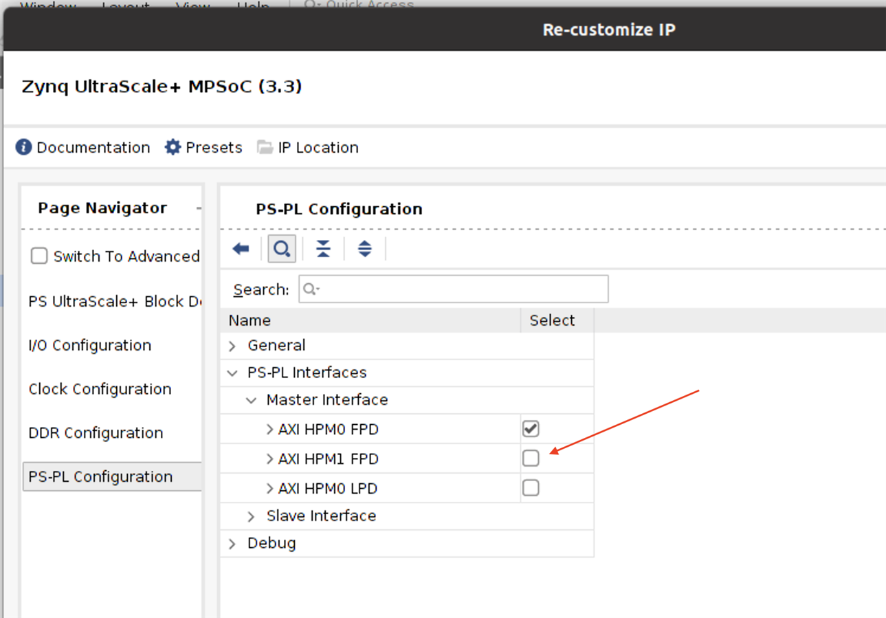
The question I had though was: how do you relate the parameter value CONFIG.PSU__USE__M_AXI_GP1 (0) to Interface M_AXI_HPM1_FPD? Master AXI is easy of course, but GP1 to HPM1_FPD? Is there a document that gives the name translations?
There is a TCL command document you can find online or in DocNav for the basic command structure but the way I could relate these particular values was with the Zynq UltraScale+ MPSoc Processing System V3.3 Product Guide. Observe the link 'Documentation' at the top of the Re-customise IP dialog shown above. Click on that and select the option 'Product Guide'. Appendix C has the parameters that can be used, e.g. PSU__USE__M_AXI_GP1. Appendix B has the port descriptions and searching for HPM1 gives Table B-45: M_AXI_HPM1_FPD which has contents related to GP1. That’s the only way of matching I can find. It seems a little convoluted and potentially error prone so if someone knows better, please comment below.
I also had a further question: how do you know it is SIN and SOUT on the UART IP that needs to be used - a not unreasonable expectation is that the ports would be labelled RX and TX?
Again, look at the Product Guide for the UART IP. Double-click the IP to bring up the Re-customise IP dialog and select the Product Guide from the Documentation link at the top of the dialog. You can find port descriptions there which clearly indicate SIN and SOUT are what is needed.
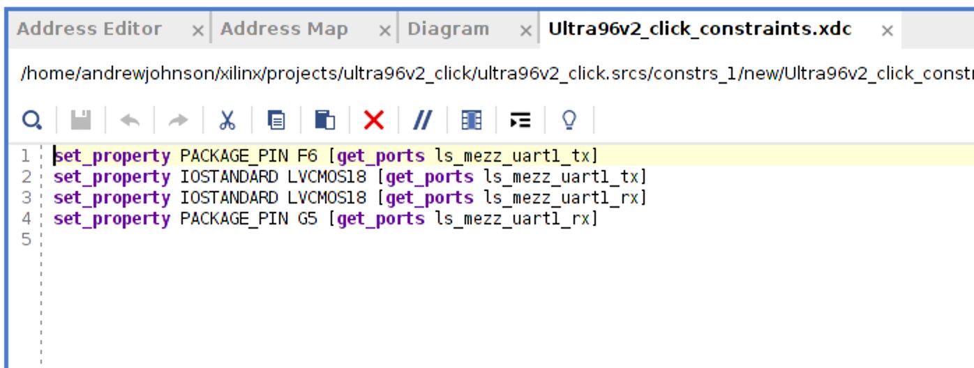
Constraints
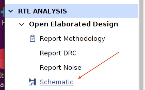
Moving on, the created ports must be constrained to the specific PL pins identified earlier in the video. The simple approach is as described in the video: copy the relevant entries from the Master Constraints document provided. That, however, doesn't really help in understanding how to set up constraints but there is an alternative route. You must have a top level file - create the HDL wrapper first, assuming the Output Objects have been generated. Also, follow the video to create a Constraints file and make it the target - this option appears when you create it. DO NOT have it open in the editor as it is going to be updated by Vivado. Under RTL Analysis > Open Elaborated Design select Schematic.
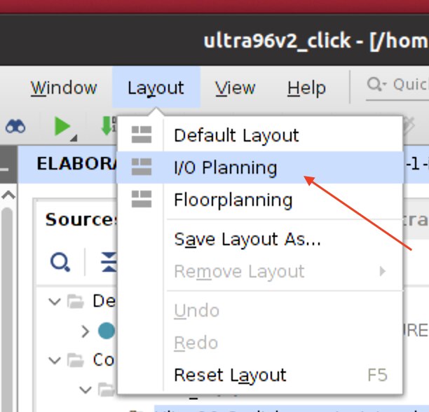
This will open Elaborated Design and a simple schematic of the design. Use the Layout menu and select I/O Planning.
This will add a tab or two at the bottom of Vivado, assuming you haven't moved the IDE panels around, and should populate the two pins that need ‘planning’ on the I/O Ports - you may need to open up some of the hierarchy.
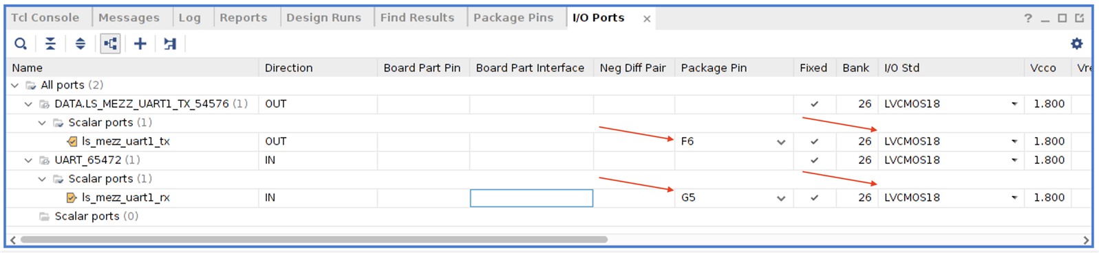
In here then, you can select the package pin, the bank and the IO Standard (power) for the pins as determined from the Ultra96V2 schematic and Mezzanine schematic, essentially, the same values as used in the workshop video/master constraints file. Save the Elaborated Design and these entries will be added into the constraints file: note that the syntax is slightly different to the video which is likely to do with advances in the tools since that master file was created. You can then close Elaborated Design.
Creating Custom IP
I've created a separate post for this as it's interesting enough in its own right, and way too long to incorporate into this one. Working it out has given me a good insight into how I might create my own IP.
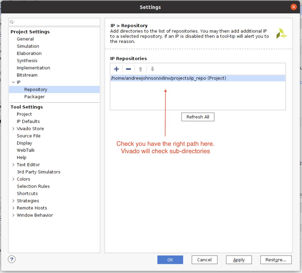
If you follow those steps you may need to adjust your Project's IP Repository setting, at least check it:
When it comes to creating the PWM port for the Mezzanine, you can use the TCL command but if you want to do it through the UI then it should look like this:
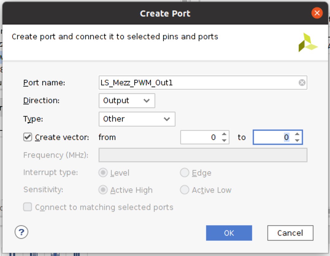
It's created as a Vector as that is how it is defined in the IP code.
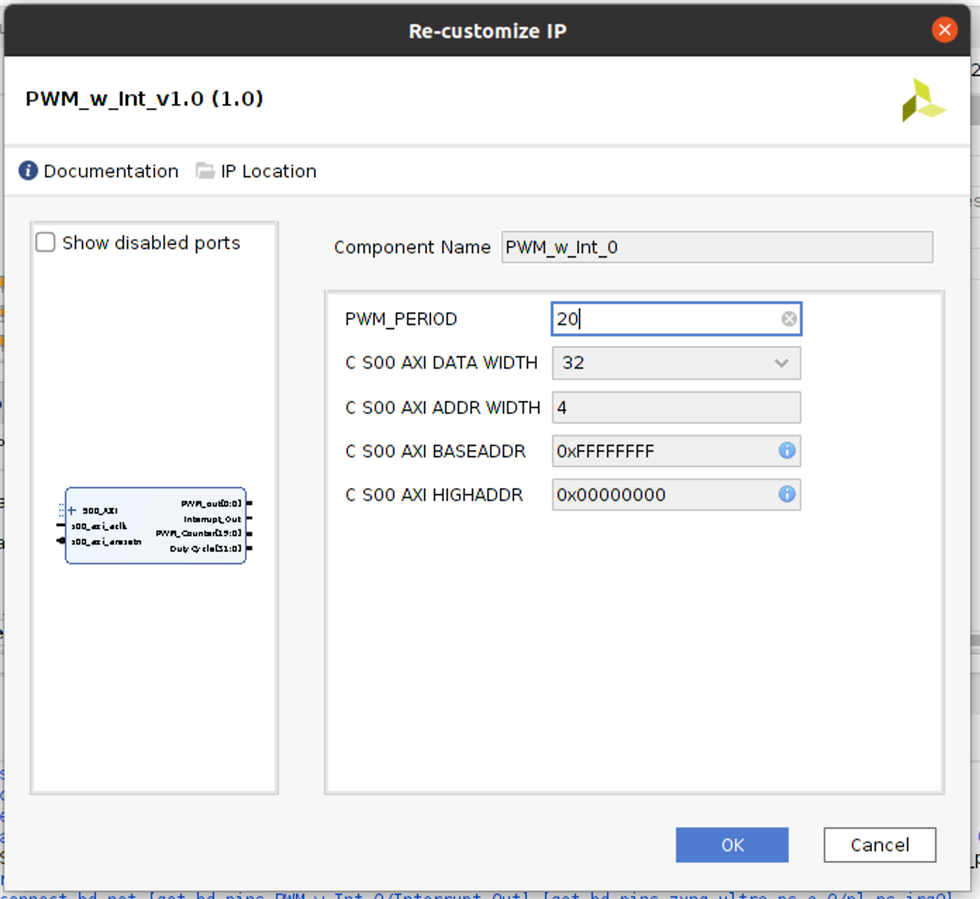
The Period for the Duty Cycle was created as a Parameter and doesn't appear as an Input Port on the Block Diagram. To change this value, double click on the PWM IP to Re-Customise IP and you can change it there:
Setting the PWM Pin: This can be done the same way as noted above. Alternatively, open the Constraints file, copy existing lines and change the relevant values.
The Makefile
If you created your own IP following the steps in the linked blog post, the makefile is created correctly and there should be no issue when you come to build the platform in Vitis.
Finishing up in Vivado
Not mentioned in the video, but once you have generated the bitstream don't forget to File > Export > Export Hardware including the bitstream.
I don't have anything to add to the Vitis element of this, except it's worth going through the code to see how it works and, in particular, interrupts. As an aside, the Standalone environments in the FSBL and PMU could have the UARTs changed from UART_0 to UART_1 in case you want to attach a serial terminal to the com port for the JTAG pod and look at the debug settings for those two elements. It's come to be a bit of a habit for me to do that.
Hopefully this is of interesting in exploring some of the things that were done in a little more detail. Any tips/feedback would be most welcome as I'm no expert at this!
Top Comments