element14 Community
element14 Community
    Register Log In
  • Site
  • Search
  • Log In Register
  • Community Hub
    Community Hub
    • What's New on element14
    • Feedback and Support
    • Benefits of Membership
    • Personal Blogs
    • Members Area
    • Achievement Levels
  • Learn
    Learn
    • Ask an Expert
    • eBooks
    • element14 presents
    • Learning Center
    • Tech Spotlight
    • STEM Academy
    • Webinars, Training and Events
    • Learning Groups
  • Technologies
    Technologies
    • 3D Printing
    • FPGA
    • Industrial Automation
    • Internet of Things
    • Power & Energy
    • Sensors
    • Technology Groups
  • Challenges & Projects
    Challenges & Projects
    • Design Challenges
    • element14 presents Projects
    • Project14
    • Arduino Projects
    • Raspberry Pi Projects
    • Project Groups
  • Products
    Products
    • Arduino
    • Avnet & Tria Boards Community
    • Dev Tools
    • Manufacturers
    • Multicomp Pro
    • Product Groups
    • Raspberry Pi
    • RoadTests & Reviews
  • About Us
    About the element14 Community
  • Store
    Store
    • Visit Your Store
    • Choose another store...
      • Europe
      •  Austria (German)
      •  Belgium (Dutch, French)
      •  Bulgaria (Bulgarian)
      •  Czech Republic (Czech)
      •  Denmark (Danish)
      •  Estonia (Estonian)
      •  Finland (Finnish)
      •  France (French)
      •  Germany (German)
      •  Hungary (Hungarian)
      •  Ireland
      •  Israel
      •  Italy (Italian)
      •  Latvia (Latvian)
      •  
      •  Lithuania (Lithuanian)
      •  Netherlands (Dutch)
      •  Norway (Norwegian)
      •  Poland (Polish)
      •  Portugal (Portuguese)
      •  Romania (Romanian)
      •  Russia (Russian)
      •  Slovakia (Slovak)
      •  Slovenia (Slovenian)
      •  Spain (Spanish)
      •  Sweden (Swedish)
      •  Switzerland(German, French)
      •  Turkey (Turkish)
      •  United Kingdom
      • Asia Pacific
      •  Australia
      •  China
      •  Hong Kong
      •  India
      •  Japan
      •  Korea (Korean)
      •  Malaysia
      •  New Zealand
      •  Philippines
      •  Singapore
      •  Taiwan
      •  Thailand (Thai)
      •  Vietnam
      • Americas
      •  Brazil (Portuguese)
      •  Canada
      •  Mexico (Spanish)
      •  United States
      Can't find the country/region you're looking for? Visit our export site or find a local distributor.
  • Translate
  • Profile
  • Settings
FPGA
  • Technologies
  • More
FPGA
Blog VHDL design for ROHM Heart Rate sensor BH1790 - try i2c
  • Blog
  • Forum
  • Documents
  • Quiz
  • Events
  • Polls
  • Files
  • Members
  • Mentions
  • Sub-Groups
  • Tags
  • More
  • Cancel
  • New
Join FPGA to participate - click to join for free!
  • Share
  • More
  • Cancel
Group Actions
  • Group RSS
  • More
  • Cancel
Engagement
  • Author Author: Jan Cumps
  • Date Created: 22 Jan 2022 11:31 AM Date Created
  • Views 7413 views
  • Likes 5 likes
  • Comments 14 comments
  • i2c
  • fpga
  • vhdl
  • summer_of_fpga
Related
Recommended

VHDL design for ROHM Heart Rate sensor BH1790 - try i2c

Jan Cumps
Jan Cumps
22 Jan 2022
VHDL design for ROHM Heart Rate sensor BH1790 - try i2c

I'm going to try and run an i2c design in VHDL fabric. For self-training.
The target device is the Rohm BH1790 optical heart rate sensor.
It's a device where the i2c protocol is straightforward but strict. A good candidate for training - a RTL state machine should be able to control the flow.

What I'd like to achieve is: controlling the complete sampling part of heart rate sensor in plain VHDL/RTL, portable/independent of FPGA make. Make the raw data available.
Then, there is a second part of interpreting/filtering the raw data.
I'm going to start doing that in software, then try translating that into FPGA designs. These may be pure VHDL, or Xilinx proprietary.
If all of that is successful, I'd like to use DMA and streaming to provide that data to a program. That's definitely going to be device dependent.
The exercise is broken up in a few posts. I write as I go. This one checks out the i2c IP I'd like to use for the design.

First, I tested this sensor with Rohm's original code on an Arduino. An exercise to know how it works, and view the communication.
It's easier to design for something that you know how to operate. Because only the FPGA/VHDL part is the unknown. I understand the IC and its protocol.

i2c IP

Vivado / Zynq come with smart i2c IP. In two flavours*: to be used within the fabric, and a version that can be used in a MicroBlaze.
I'm after one that's implemented in fabric. I'm not using Xilinx' proprietary implementation, because I try to improve my VHDL skills in this design. Not my knowledge of Xilinx IP 
*I believe there's also i2c support in the Linux/PS part of the Zynq, comparable to i2c on a Pi. That's not what I'm trying to learn here.

On the other hand, I'd like to reuse an existing VHDL i2c design.
I'd first like to implement a design that uses a working i2c IP. I'm not up to writing my own implementation of that yet.
I landed with a design posted on Digi-Key's Tech Forum. Like Avnet's element14, Digi-Key also has a community. I found this design over there.
It's written - and improved over time - by Scott Larson. Written for Quartus II (Intel/Altera).
Ideally, the end result should be cross-community, cross-distributor, cross-manufacturer.
The source code and related blog don't mention a license. I expect that writing about it, and change some parts of the code (see table below), is in line with community behaviour.
I will restrict my blogs to changes I made to the original code, and why. The ZIP attachments will contain the adapted code with link to the original in the source files.

VHDL buffer in a top design

The i2c design of Scott Larson uses an output of type BUFFER for the ack_error flag.
ack_error : BUFFER STD_LOGIC; --flag if improper acknowledge from slave

A VHDL BUFFER is an output port, that can be read to and written from inside the architecture.
A normal OUT port can't be read from inside an implementation. You can assign it a value.

The consequence of BUFFER type is that it needs to be implemented all the way up in the design. Upstream ports that connect to it, need to be BUFFER too.
But that's not always what you desire. In the end, for external design that uses the IP, the flag is just an output. Type BUFFER is used because that's how the internal implementation of the IP uses it.

There are alternatives to BUFFER though. One of them is to define the flag as OUT. Then create a SIGNAL internally in the IP that can be written to and read from.
In the IP implementation, assign that SIGNAL to the out pin.
It's explained here: How to stop using "buffer" ports in VHDL?
How does this change Scott Larson's VHDL?

Original:

ack_error : BUFFER STD_LOGIC; --flag if improper acknowledge from slave
-- ...
  IF(sda /= '0' OR ack_error = '1') THEN --no-acknowledge or previous no-acknowledge
    ack_error <= '1'; --set error output if no-acknowledge
-- ...

Revised:

ack_error : OUT STD_LOGIC; --flag if improper acknowledge from slave
-- ...
SIGNAL s_ack_error : STD_LOGIC;
-- ...
  IF(sda /= '0' OR s_ack_error = '1') THEN --no-acknowledge or previous no-acknowledge
    s_ack_error <= '1'; --set error output if no-acknowledge
-- ...
ack_error <= s_ack_error;

The i2c IP interface

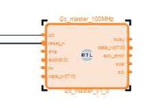
The i2c IP has, like all IPs, a set of input and output connections.
They are very similar to the APIs you have access to in a microcontroller's i2c driver.
image

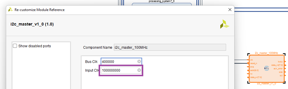
There are 2 variables that are set as GENERIC. clock frequency and i2c frequency.
They are set to 500 MHz and 400 kHz. You can overwrite those in a Vivado block design without wrapping or coding:
image

I kept the 400 kHz i2c speed. The heart rate sensor supports it.
I adapted the input clock frequency. I've set it equal to the Fabric ClocK 1 speed. That's the clock I'm attaching the IP to.

Open Drain SDA and SCL

i2c protocol uses open drain active devices, in combination with pull-up resistors.
In a constraint file, there's no way to define it. The way to do it in RTL, is by setting the output to High-impedance instead of '1' when driving an output high.
The SDA is bi-directional, input and output. But that doesn't add complexity. Implementing it is simpler than I thought.
You can just ignore any state (in or out), except output high. For output high, you assign high impedance:

sda <= '0' WHEN sda_ena_n = '0' ELSE 'Z';

Design Decision for the next post

I'm going to write a IP that reflects the BH11790 sensor.
I could have instantiated the i2c IP in its code. But I'd like to write a sensor class that's isolated from that.
The plan is that it exposes pins that can be connected to the i2c IP, and that I link them together in the block design.
It's the first time that I do this, so it may or may not be the right decision. The future will tell ...

  • Sign in to reply
Parents
  • Jan Cumps
    Jan Cumps over 4 years ago

    A rudimentary 1st stab at the state machine for the BH1790 VHDL block:

    LIBRARY ieee;
    USE ieee.std_logic_1164.all;
    USE ieee.std_logic_unsigned.all;
    use ieee.numeric_std.all;
    
    ENTITY bh1790 IS
      GENERIC(
        input_clk : INTEGER := 50_000_000;   --input clock speed from user logic in Hz
        sampling_count   : INTEGER := 32;    --sampling count - samples are grouped by this count (one I implement it)
        sampling_frequency : integer := 32); -- sampling frequency in Hz
      PORT(
        clk       : IN     STD_LOGIC;                    --system clock
        reset_n   : IN     STD_LOGIC;                    --active low reset
        -- data interface
        data_out  : OUT    std_logic_vector(31 downto 0);-- 32 bit raw sensor data 
                                                         -- [1][0][3][2] - [0x5500][0x5400][0x5700][0x5600]
                                                         -- [ledoff data][ledon data]
        debug_register : out std_logic_vector(7 downto 0); -- to remove. 8 pins to validate internal statuses, clocks, ...
        -- connections to i2c driver
        ena       : OUT    STD_LOGIC;                    --latch in command
        addr      : OUT    STD_LOGIC_VECTOR(6 DOWNTO 0); --address of target slave
        rw        : OUT    STD_LOGIC;                    --'0' is write, '1' is read
        data_wr   : OUT    STD_LOGIC_VECTOR(7 DOWNTO 0); --data to write to slave
        busy      : IN     STD_LOGIC;                    --indicates transaction in progress
        data_rd   : IN     STD_LOGIC_VECTOR(7 DOWNTO 0); --data read from slave
        ack_error : IN     STD_LOGIC);                   --flag if improper acknowledge from slave
    END bh1790;
    
    ARCHITECTURE bh1790 OF bh1790 IS
      CONSTANT divider  :  INTEGER := (input_clk/sampling_frequency); 
      TYPE machine_state IS (reset,init,active); --needed states
      signal s_debug_register : std_logic_vector (7 downto 0) := (others => '0');
      signal state : machine_state;
      
    procedure i2c_commands (
     init : in STD_LOGIC) is -- if init, the reset command will be added. In that case, mandatory wait 1/32 second
    begin
      -- todo: write the i2c registers.
      if (init = '1') then   -- only reset during initialisation.
        -- reset register
      end if; 
      -- register 1, 2, 3, refresh always as advised by datasheet
    end i2c_commands; 
      
    BEGIN
    
      PROCESS(clk, reset_n)
        VARIABLE sample_clock_count  :  INTEGER RANGE 0 TO divider;  --timing for clock generation
        VARIABLE samples_count : integer range 0 to sampling_count;
        
      BEGIN
        IF(reset_n = '0') THEN                --reset asserted
          state <= reset;
          sample_clock_count := 0;
          samples_count := 0;
          s_debug_register(7 downto 0) <= (others => '0'); -- debug: reset status
        ELSIF(rising_edge(clk)) THEN
            s_debug_register(0) <= '1'; -- todo remove debug: reset status
            sample_clock_count := sample_clock_count + 1;               --continue clock generation timing
            if (sample_clock_count = divider) then -- do every sample frequency tick
              s_debug_register(1) <= not s_debug_register(1); -- todo remove debug: toggle each time
              case  state is
                when reset =>
                  i2c_commands('1');
                when others =>
                  -- there should be no default handling
              end case;
              sample_clock_count := 0;
              samples_count := samples_count + 1;
              if (samples_count = sampling_count) then -- do every sampling_count sample tick
                s_debug_register(2) <= '1'; -- todo remove 
                samples_count := 0;            
              else -- do every sample tick except on the sampling_count'st sample
                s_debug_register(2) <= '0'; -- todo remove       
              end if;
            end if;
        END IF;
      END PROCESS;  
    
      debug_register (7 downto 0) <= s_debug_register (7 downto 0);
      
      END bh1790;

    Not functional at all, but you can start to sense how the object flow will work.
    Some VHDL constructs used:

    • overridable generic for clock frequency, desired sample frequency and desired sample count for grouping, filtering and calculation
    • a procedure, with 1 input parameter
    • state machine with CASE and a custom TYPE for the states
    • Cancel
    • Vote Up 0 Vote Down
    • Sign in to reply
    • More
    • Cancel
  • Jan Cumps
    Jan Cumps over 4 years ago in reply to Jan Cumps

    Time to start working on real i2c communication. The hardware is set up:

    image

    The heart rate monitor is connected to the 2 i2c pins defined in the constraints. PMODA 1 (scl) and 2 (sda):

    image

    I've hooked up a protocol analyser. This should show me if traffic is valid.

    • Cancel
    • Vote Up 0 Vote Down
    • Sign in to reply
    • More
    • Cancel
Comment
  • Jan Cumps
    Jan Cumps over 4 years ago in reply to Jan Cumps

    Time to start working on real i2c communication. The hardware is set up:

    image

    The heart rate monitor is connected to the 2 i2c pins defined in the constraints. PMODA 1 (scl) and 2 (sda):

    image

    I've hooked up a protocol analyser. This should show me if traffic is valid.

    • Cancel
    • Vote Up 0 Vote Down
    • Sign in to reply
    • More
    • Cancel
Children
  • Jan Cumps
    Jan Cumps over 4 years ago in reply to Jan Cumps

    Baby steps again. I see that there is intent to communicate.
    The capture is not what I expected, but at least I know that the right pins are addressed.

    image

    • Cancel
    • Vote Up 0 Vote Down
    • Sign in to reply
    • More
    • Cancel
element14 Community

element14 is the first online community specifically for engineers. Connect with your peers and get expert answers to your questions.

  • Members
  • Learn
  • Technologies
  • Challenges & Projects
  • Products
  • Store
  • About Us
  • Feedback & Support
  • FAQs
  • Terms of Use
  • Privacy Policy
  • Legal and Copyright Notices
  • Sitemap
  • Cookies

An Avnet Company © 2026 Premier Farnell Limited. All Rights Reserved.

Premier Farnell Ltd, registered in England and Wales (no 00876412), registered office: Farnell House, Forge Lane, Leeds LS12 2NE.

Follow element14

  • X
  • Facebook
  • linkedin
  • YouTube