


I'm trying to control an unknown stepper motor with the high-end timer (NHET) module of a Texas Instruments Hercules microcontroller
I got a freebee from TI almost a year ago. An unknown stepper motor, a driver board and a Hercules RM57 LaunchPad. The code to run the motor was expected to arrive too (it was an assignment for an internal) but that never materialised. In this blog series I'm trying to program the NHET module so that it sends the right signals to make the stepper step.
In the fourth post I check the PWM signal that the MSP430 generates for the ramp-up, steady and ramp-down stages. And what it does when you ask for a fixed number of steps. |

MSP430 Generates Period-modulated PWM
(somehow this title sounds recursive, I'm open to a better suggestion)
The typical way we deal with PWM is using duty-cycle modulation.
For this application though, where we're trying to ramp up a stepper motor gradually, period modulation is needed.
The image below is a capture of the PWM that the MSP430 timers generate to ramp up the motor from stance,
with 128 pulses per second as start speed, 512 PPS as stable speed and an acceleration rate of 128.
(click the image to see it at a useful size)

You can see that the time between the pulses is decreasing - the motor is speeding up.
The capture doesn't have the full reach from start to end - I ran out of logic analyser memory.
It's good enough to show the ramp-up though.
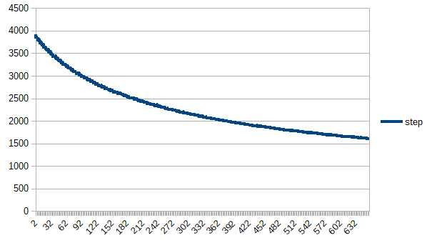
When the motor starts, the time between two level shifts is 3925 ns. So approximately 7850 ns for a full pulse (a PWM *** has two level shifts).
That matches with the initial setting of 128 PPS (the theoretical value is 7812.5 ns). The timer outputs 127.39 pulses per second at the start.
After 1 second, the time between two pulses is 2006 ns (see the attached spreadsheet). The time for a pulse = 4012 ns. So after a second the MSP430 outputs 249.25 pulses per second.
At this point I give up on the math. I leave it to the reader to check if an increase from 128 to 250 pulses is an increase rate of 128 (because I am old and my brain blocks right now  ).
).
Finally the MSP430 Timer Code
Here are the chunks of code that prime the timers and adjust them during runtime.
Init
void Initialize()
{
    // Setup CLKs


    // Stop Watchdog Timer
    WDTCTL = WDTPW | WDTHOLD;
    // Set DCO to 16MHz
    DCOCTL = 0x00;
    DCOCTL = CALDCO_16MHZ;
    BCSCTL1 = CALBC1_16MHZ;
    // Set SMCLK to 2MHz
    BCSCTL2 |= DIVS_3;
    // ACLK = VLO
    BCSCTL3 |= LFXT1S_2;


    // Configure Port Directions and Peripherals as Needed


    // Configure GPIO
    P1SEL  &= ~(POT | nSLEEP);
    P1SEL2 &= ~(POT | nSLEEP);


    P1DIR  |= (POT | nSLEEP);
    P1OUT  |= (POT | nSLEEP);


    P2SEL  &= ~(RESET | STEP_AIN1 | DIR_AIN2 | BIN2 | BIN1 | nFAULT | nSTALL);
    P2SEL2 &= ~(RESET | STEP_AIN1 | DIR_AIN2 | BIN2 | BIN1 | nFAULT | nSTALL);


    P2DIR |= (RESET | STEP_AIN1 | DIR_AIN2 | BIN2 | BIN1);
    P2OUT &= ~(RESET | STEP_AIN1 | DIR_AIN2 | BIN2 | BIN1);


    P2DIR &= ~(nFAULT | nSTALL);
    P2REN |= (nFAULT | nSTALL);


    P3DIR |= (BIT0 | BIT1 | BIT2 | BIT3 | BIT4 | BIT5 | BIT6 | BIT7);
    P3OUT &= ~(BIT0 | BIT1 | BIT2 | BIT3 | BIT4 | BIT5 | BIT6 | BIT7);


    // Configure SPI
    // Recommended USCI initialization/re-configure process
    // 1. Set UCSWRST (BIS.B #UCSWRST,&UCxCTL1)
    // 2. Initialize all USCI registers with UCSWRST=1 (including UCxCTL1)
    // 3. Configure ports
    // 4. Clear UCSWRST via software (BIC.B #UCSWRST,&UCxCTL1)
    // 5. Enable interrupts (optional) via UCxRXIE and/or UCxTXIE


    // 1)
    UCB0CTL1 = UCSWRST;


    // 2)
    P2DIR |= CS;
    P2OUT &= ~CS;
    P1SEL |= SCLK | SDATO |  SDATI;
    P1SEL2 |= SCLK | SDATO |  SDATI;


    // 3) 3-pin, 8-bit SPI master
    UCB0CTL0 |= UCCKPH | UCMSB | UCMST | UCSYNC;
    UCB0CTL1 |= UCSSEL_2;   // SMCLK


    // 4)
    UCB0CTL1 &= ~UCSWRST;
    // End SPI Configure


    // UART Initialization
    uartInit();


    // Enables LPM Interrupts
    __bis_SR_register(GIE);


    // GUI Composer Monitor Initialization
    ClearBufferRelatedParam();


    // Set Default GPIO Settings
    G_nSLEEP = low;
    G_RESET = low;
    G_STEP_AIN1 = low;
    G_DIR_AIN2 = low;
    G_BIN2 = low;
    G_BIN1 = low;
    G_nFAULT = high;
    G_nSTALL = high;
    UpdateGPIO();


    // Setup Pin for Timer Output
    P2DIR |= STEP_AIN1;
    P2SEL |= STEP_AIN1;
    P2SEL2 &= ~STEP_AIN1;


    // Load Default Speed Profile Values
    G_START_STOP_SPEED = DEFAULT_START_STOP_SPEED;
    G_TARGET_SPEED = DEFAULT_TARGET_SPEED;
    G_ACCEL_RATE = DEFAULT_ACCEL_RATE;
    G_TOTAL_NUM_STEPS = DEFAULT_NUM_STEPS;


    // Set Default Register Settings
    // CTRL Register
    G_CTRL_REG.Address     = 0x00;
    G_CTRL_REG.DTIME     = 0x03;
    G_CTRL_REG.ISGAIN     = 0x03;
    G_CTRL_REG.EXSTALL     = 0x00;
    G_CTRL_REG.MODE     = 0x03;
    G_CTRL_REG.RSTEP     = 0x00;
    G_CTRL_REG.RDIR     = 0x00;
    G_CTRL_REG.ENBL     = 0x01;


    // TORQUE Register
    G_TORQUE_REG.Address = 0x01;
    G_TORQUE_REG.SIMPLTH = 0x00;
    G_TORQUE_REG.TORQUE  = 0xBA;


    // OFF Register
    G_OFF_REG.Address     = 0x02;
    G_OFF_REG.PWMMODE     = 0x00;
    G_OFF_REG.TOFF         = 0x30;


    // BLANK Register
    G_BLANK_REG.Address = 0x03;
    G_BLANK_REG.ABT     = 0x01;
    G_BLANK_REG.TBLANK     = 0x08;


    // DECAY Register.
    G_DECAY_REG.Address = 0x04;
    G_DECAY_REG.DECMOD  = 0x03;
    G_DECAY_REG.TDECAY     = 0x10;


    // STALL Register
    G_STALL_REG.Address = 0x05;
    G_STALL_REG.VDIV     = 0x03;
    G_STALL_REG.SDCNT     = 0x03;
    G_STALL_REG.SDTHR     = 0x40;


    // DRIVE Register
    G_DRIVE_REG.Address = 0x06;
    G_DRIVE_REG.IDRIVEP = 0x00;
    G_DRIVE_REG.IDRIVEN = 0x00;
    G_DRIVE_REG.TDRIVEP = 0x01;
    G_DRIVE_REG.TDRIVEN = 0x01;
    G_DRIVE_REG.OCPDEG     = 0x01;
    G_DRIVE_REG.OCPTH     = 0x01;


    // STATUS Register
    G_STATUS_REG.Address = 0x07;
    G_STATUS_REG.STDLAT  = 0x00;
    G_STATUS_REG.STD     = 0x00;
    G_STATUS_REG.UVLO    = 0x00;
    G_STATUS_REG.BPDF    = 0x00;
    G_STATUS_REG.APDF    = 0x00;
    G_STATUS_REG.BOCP    = 0x00;
    G_STATUS_REG.AOCP    = 0x00;
    G_STATUS_REG.OTS     = 0x00;
    WriteAllRegisters();
}
main loop. housekeeping, then sleep until timer wakes us up
    while (1)
    {
        // Update Functions
        UpdateGPIO();
        UpdateDRV8711Registers();
        UpdateFullScaleCurrent();
        UpdateStepperMotionProfile();
        // Enter LPM and wake up when needed
        __bis_SR_register(LPM0_bits + GIE);
    }
Interrupt handling (timers get modified during the interrupts, sleeping microcontroller is woken up)
/****************************Interrupt Service Routines*****************************/


#pragma vector=PORT1_VECTOR, PORT2_VECTOR, ADC10_VECTOR, \
        USCIAB0TX_VECTOR, TIMER0_A0_VECTOR, TIMER0_A1_VECTOR, \
        COMPARATORA_VECTOR, NMI_VECTOR
__interrupt void Trap_ISR(void) {}


#pragma vector=TIMER1_A0_VECTOR
__interrupt void Timer1_A0(void)
{
    // Update Timer at End of PWM Period
    if (G_LOAD_CCR_VALS == true)
    {
        G_CUR_SPEED = G_CUR_SPEED_TEMP;
        TA1CCR0 = G_TA1CCR0_TEMP;
        TA1CCR1 = G_TA1CCR1_TEMP;
        G_LOAD_CCR_VALS = false;
    }
}


#pragma vector=TIMER1_A1_VECTOR
__interrupt void Timer1_A1(void)
{
    switch (TA1IV)
    {
        case TA1IV_NONE: break;         // Vector 0: No Interrupt
        case TA1IV_TACCR1:              // Vector 2: CCR1 CCIFG
        {
            // Increment Step Counter
            G_CUR_NUM_STEPS++;
            if (G_CUR_NUM_STEPS == G_TOTAL_NUM_STEPS)
            {
                __bic_SR_register_on_exit(LPM0_bits);
            }
            TA1CCTL1 &= ~CCIFG;
            break;
        }
        case TA1IV_TACCR2:              // Vector 4: CCR2 CCIFG
        {
            TA1CCTL2 &= ~CCIFG;
            break;
        }
        case TA1IV_6: break;            // Vector 6: Reserved CCIFG
        case TA1IV_8: break;            // Vector 8: Reserved CCIFG
        case TA1IV_TAIFG:               // Vector 10: Overflow
        {
            TACTL &= ~TAIFG;
            break;
        }
        default: break;
    }
}


#pragma vector=WDT_VECTOR
__interrupt void WatchDog_Timer(void)
{
    // Signal Main Thread to Calculate Next Speed Value
    G_ACCEL_FLAG = true;
    // Wake Up the Main Thread
    __bic_SR_register_on_exit(LPM0_bits);
}
I'm skipping GPIO part. The motor is only stepped here if you bypass the indexer. Not what I'm looking for.
Now the real brains. Calculating and applying the profiles.
void UpdateFullScaleCurrent()
{
    // Calculate the 100% Chopping Current Level
    if ((G_CTRL_REG.ISGAIN != G_ISGAIN_OLD) || (G_TORQUE_REG.TORQUE != G_TORQUE_OLD))
    {
        // Parse ISGAIN
        unsigned int temp_isgain;
        if (G_CTRL_REG.ISGAIN == 0)
            temp_isgain = 5;
        else if (G_CTRL_REG.ISGAIN == 1)
            temp_isgain = 10;
        else if (G_CTRL_REG.ISGAIN == 2)
            temp_isgain = 20;
        else if (G_CTRL_REG.ISGAIN == 3)
            temp_isgain = 40;
        else
            temp_isgain = 5;


        // Calculate Floating Point Value
        G_FULL_SCALE_CURRENT = (2.75 * (float)G_TORQUE_REG.TORQUE) / (256 * (float)temp_isgain * 0.05);
        G_ISGAIN_OLD = G_CTRL_REG.ISGAIN;
        G_TORQUE_OLD = G_TORQUE_REG.TORQUE;
    }
}


void UpdateStepperMotionProfile()
{
    if (G_BYPASS_INDEXER == false)
    {
        // Motion Profile State Machine
        // Speed Profile Motor Start
        if ((G_SPEED_PROFILE == true) && (G_SPEED_PROFILE_LOCK == false))
        {
            G_MOTOR_STATE = SPD_START;
        }
        // Speed Profile Motor Accelerating
        else if ((G_CUR_SPEED < G_TARGET_SPEED) && (G_SPEED_PROFILE == true) && (G_SPEED_PROFILE_LOCK == true))
        {
            G_MOTOR_STATE = SPD_ACCEL;
        }
        // Speed Profile Motor Stable
        else if ((G_CUR_SPEED == G_TARGET_SPEED) && (G_SPEED_PROFILE == true) && (G_SPEED_PROFILE_LOCK == true))
        {
            G_MOTOR_STATE = SPD_STABLE;
        }
        // Speed Profile Motor Decelerating
        else if ((G_CUR_SPEED > G_START_STOP_SPEED) && (G_SPEED_PROFILE == false) && (G_SPEED_PROFILE_LOCK == true))
        {
            G_MOTOR_STATE = SPD_DECEL;
        }
        // Speed Profile Motor Stop
        else if ((G_CUR_SPEED == G_START_STOP_SPEED) && (G_SPEED_PROFILE == false) && (G_SPEED_PROFILE_LOCK == true))
        {
            G_MOTOR_STATE = SPD_STOP;
        }
        // Step Profile Motor Start
        else if ((G_STEP_PROFILE == true) && (G_STEP_PROFILE_LOCK == false))
        {
            G_MOTOR_STATE = STP_START;
        }
        // Step Profile Motor Accelerating
        else if ((G_CUR_NUM_STEPS < G_STEPS_TO_ACCEL) && (G_STEP_PROFILE == true) && (G_STEP_PROFILE_LOCK == true))
        {
            G_MOTOR_STATE = STP_ACCEL;
        }
        // Step Profile Motor Stable
        else if ((G_CUR_NUM_STEPS < (G_TOTAL_NUM_STEPS - G_STEPS_TO_ACCEL)) && (G_STEP_PROFILE == true) && (G_STEP_PROFILE_LOCK == true))
        {
            G_MOTOR_STATE = STP_STABLE;
        }
        // Step Profile Motor Decelerating
        else if ((G_CUR_NUM_STEPS >= (G_TOTAL_NUM_STEPS - G_STEPS_TO_ACCEL)) && (G_CUR_NUM_STEPS < G_TOTAL_NUM_STEPS) && (G_STEP_PROFILE == true) && (G_STEP_PROFILE_LOCK == true))
        {
            G_MOTOR_STATE = STP_DECEL;
        }
        // Step Profile Motor Stop
        else if ((G_CUR_NUM_STEPS >= G_TOTAL_NUM_STEPS) && (G_STEP_PROFILE == true) && (G_STEP_PROFILE_LOCK == true))
        {
            G_MOTOR_STATE = STP_STOP;
        }
        // Step Profile Force Motor Stop
        else if ((G_STEP_PROFILE == false) && (G_STEP_PROFILE_LOCK == true))
        {
            G_MOTOR_STATE = STP_STOP;
        }
        // Motor Hold
        else
        {
            G_MOTOR_STATE = HOLD;
        }


        // Speed Profile
        SpeedProfile();
        // Step Profile
        StepProfile();
    }
}
void SpeedProfile()
{
    // Motor Start
    if (G_MOTOR_STATE == SPD_START)
    {
        G_SPEED_PROFILE_LOCK = true;
        // Set the Start Speed (Cannot Overflow the Timer Register)
        G_CUR_NUM_STEPS = 0;
        // Value Check
        if (G_START_STOP_SPEED > G_TARGET_SPEED)
        {
            G_START_STOP_SPEED = G_TARGET_SPEED;
        }
        G_CUR_SPEED = G_START_STOP_SPEED;
        TA1CCR0 = (SMCLK_MHz*1000000)/G_START_STOP_SPEED;
        TA1CCR1 = ((SMCLK_MHz*1000000)/G_START_STOP_SPEED) >> 1;


        // Determine the Acceleration Increment
        // Watchdog Timer Fires Every 16.384ms, ~61.035 Interupts/s (Accel Rate Cannot be Less Than 64)
        // Round Accelerat Rate to Increment of 64
        G_ACCEL_RATE = (G_ACCEL_RATE >> 6) << 6;
        G_SPEED_INCR = G_ACCEL_RATE >> 6;


        // Set the Timer Output Low
        TA1CCTL1 = OUTMOD_0;
        P2OUT &= ~STEP_AIN1;
        // Setup the Output and Interrupt
        TA1CCTL0 = CCIE;
        TA1CCTL1 = OUTMOD_3 | CCIE;
        // Start the Timer
        TA1CTL = TASSEL_2 | MC_1 | TACLR;


        // Setup Watchdog Timer as an Interval Timer for Accel/Decel Updates
        WDTCTL = WDT_MDLY_32;
        IE1 |= WDTIE;
    }


    // Motor Accelerate
    else if ((G_MOTOR_STATE == SPD_ACCEL) && (G_ACCEL_FLAG == true))
    {
        G_ACCEL_FLAG = false;
        // Increase Speed
        if ((G_CUR_SPEED + G_SPEED_INCR) < G_TARGET_SPEED)
        {
            // Calcute Next Speed Value (Cannot Overflow the Timer Register)
            G_CUR_SPEED_TEMP = G_CUR_SPEED + G_SPEED_INCR;
            G_TA1CCR0_TEMP = (SMCLK_MHz*1000000)/G_CUR_SPEED_TEMP;
            G_TA1CCR1_TEMP = ((SMCLK_MHz*1000000)/G_CUR_SPEED_TEMP) >> 1;
            G_LOAD_CCR_VALS = true;
        }
        // Load Target Speed
        else
        {
            // Calcute Target Speed Value (Cannot Overflow the Timer Register)
            G_CUR_SPEED_TEMP = G_TARGET_SPEED;
            G_TA1CCR0_TEMP = (SMCLK_MHz*1000000)/G_TARGET_SPEED;
            G_TA1CCR1_TEMP = ((SMCLK_MHz*1000000)/G_TARGET_SPEED) >> 1;
            G_LOAD_CCR_VALS = true;
        }
    }


    // Motor Decelerate
    else if ((G_MOTOR_STATE == SPD_DECEL) && (G_ACCEL_FLAG == true))
    {
        G_ACCEL_FLAG = false;
        // Decrease Speed
        if (((G_CUR_SPEED - G_SPEED_INCR) > G_START_STOP_SPEED) && (G_CUR_SPEED > G_SPEED_INCR))
        {
            // Calcute Next Speed Value (Cannot Overflow the Timer Register)
            G_CUR_SPEED_TEMP = G_CUR_SPEED - G_SPEED_INCR;
            G_TA1CCR0_TEMP = (SMCLK_MHz*1000000)/G_CUR_SPEED_TEMP;
            G_TA1CCR1_TEMP = ((SMCLK_MHz*1000000)/G_CUR_SPEED_TEMP) >> 1;
            G_LOAD_CCR_VALS = true;
        }
        // Load Stop Speed
        else
        {
            // Calcute Stop Speed Value (Cannot Overflow the Timer Register)
            G_CUR_SPEED_TEMP = G_START_STOP_SPEED;
            G_TA1CCR0_TEMP = (SMCLK_MHz*1000000)/G_START_STOP_SPEED;
            G_TA1CCR1_TEMP = ((SMCLK_MHz*1000000)/G_START_STOP_SPEED) >> 1;
            G_LOAD_CCR_VALS = true;
        }
    }


    // Motor Stop
    else if (G_MOTOR_STATE == SPD_STOP)
    {
        // Stop Watchdog Interval Timer
        WDTCTL = WDTPW | WDTHOLD;
        IE1 &= ~WDTIE;
        // Disable Timer
        TA1CTL = TASSEL_2 | MC_0 | TACLR;
        G_CUR_SPEED = 0;
        G_SPEED_PROFILE_LOCK = false;
    }


    // Catch All
    else {}
}
void StepProfile()
{
    // Motor Start
    if (G_MOTOR_STATE == STP_START)
    {
        G_STEP_PROFILE_LOCK = true;
        // Set the Start Speed (Cannot Overflow the Timer Register)
        G_CUR_NUM_STEPS = 0;
        // Value Check
        if (G_START_STOP_SPEED > G_TARGET_SPEED)
        {
            G_START_STOP_SPEED = G_TARGET_SPEED;
        }
        G_CUR_SPEED = G_START_STOP_SPEED;
        TA1CCR0 = (SMCLK_MHz*1000000)/G_START_STOP_SPEED;
        TA1CCR1 = ((SMCLK_MHz*1000000)/G_START_STOP_SPEED) >> 1;


        // Determine the Acceleration Increment
        // Watchdog Timer Fires Every 16.384ms, ~61.035 Interupts/s (Accel Rate Cannot be Less Than 64)
        // Round Accelerat Rate to Increment of 64
        G_ACCEL_RATE = (G_ACCEL_RATE >> 6) << 6;
        G_SPEED_INCR = G_ACCEL_RATE >> 6;


        // Determine the Number of Steps to Accel/Decel
        // TODO explain this
        float time = (float)(G_TARGET_SPEED - G_START_STOP_SPEED)/(float)G_ACCEL_RATE;
        G_STEPS_TO_ACCEL = ((G_ACCEL_RATE >> 1) * (time * time)) + (G_START_STOP_SPEED * time);
        if (G_STEPS_TO_ACCEL > (G_TOTAL_NUM_STEPS >> 1))
        {
            G_STEPS_TO_ACCEL = G_TOTAL_NUM_STEPS >> 1;
        }


        // Set the Timer Output Low
        TA1CCTL1 = OUTMOD_0;
        P2OUT &= ~STEP_AIN1;
        // Setup the Output and Interrupt
        TA1CCTL0 = CCIE;
        TA1CCTL1 = OUTMOD_3 | CCIE;
        // Start the Timer
        TA1CTL = TASSEL_2 | MC_1 | TACLR;


        // Setup Watchdog Timer as an Interval Timer for Accel/Decel Updates
        WDTCTL = WDT_MDLY_32;
        IE1 |= WDTIE;
    }


    // Motor Accelerate
    else if ((G_MOTOR_STATE == STP_ACCEL) && (G_ACCEL_FLAG == true))
    {
        G_ACCEL_FLAG = false;
        // Increase Speed
        if ((G_CUR_SPEED + G_SPEED_INCR) < G_TARGET_SPEED)
        {
            // Calcute Next Speed Value (Cannot Overflow the Timer Register)
            G_CUR_SPEED_TEMP = G_CUR_SPEED + G_SPEED_INCR;
            G_TA1CCR0_TEMP = (SMCLK_MHz*1000000)/G_CUR_SPEED_TEMP;
            G_TA1CCR1_TEMP = ((SMCLK_MHz*1000000)/G_CUR_SPEED_TEMP) >> 1;
            G_LOAD_CCR_VALS = true;
        }
        // Load Target Speed
        else
        {
            // Calcute Target Speed Value (Cannot Overflow the Timer Register)
            G_CUR_SPEED_TEMP = G_TARGET_SPEED;
            G_TA1CCR0_TEMP = (SMCLK_MHz*1000000)/G_TARGET_SPEED;
            G_TA1CCR1_TEMP = ((SMCLK_MHz*1000000)/G_TARGET_SPEED) >> 1;
            G_LOAD_CCR_VALS = true;
        }
    }


    // Motor Decelerate
    else if ((G_MOTOR_STATE == STP_DECEL) && (G_ACCEL_FLAG == true))
    {
        G_ACCEL_FLAG = false;
        // Decrease Speed
        if (((G_CUR_SPEED - G_SPEED_INCR) > G_START_STOP_SPEED) && (G_CUR_SPEED > G_SPEED_INCR))
        {
            // Calcute Next Speed Value (Cannot Overflow the Timer Register)
            G_CUR_SPEED_TEMP = G_CUR_SPEED - G_SPEED_INCR;
            G_TA1CCR0_TEMP = (SMCLK_MHz*1000000)/G_CUR_SPEED_TEMP;
            G_TA1CCR1_TEMP = ((SMCLK_MHz*1000000)/G_CUR_SPEED_TEMP) >> 1;
            G_LOAD_CCR_VALS = true;
        }
        // Load Stop Speed
        else
        {
            // Calcute Stop Speed Value (Cannot Overflow the Timer Register)
            G_CUR_SPEED_TEMP = G_START_STOP_SPEED;
            G_TA1CCR0_TEMP = (SMCLK_MHz*1000000)/G_START_STOP_SPEED;
            G_TA1CCR1_TEMP = ((SMCLK_MHz*1000000)/G_START_STOP_SPEED) >> 1;
            G_LOAD_CCR_VALS = true;
        }
    }


    // Motor Stop
    else if (G_MOTOR_STATE == STP_STOP)
    {
        // Stop Watchdog Interval Timer
        WDTCTL = WDTPW | WDTHOLD;
        IE1 &= ~WDTIE;
        // Disable Timer
        TA1CTL = TASSEL_2 | MC_0 | TACLR;
        // End Step Profle
        G_CUR_SPEED = 0;
        G_STEP_PROFILE = false;
        G_STEP_PROFILE_LOCK = false;
    }


    // Catch All
    else {}
}
All code replicated here in line with (check the demo source files for the full extend of) the license:
/* --COPYRIGHT--,BSD
 * Copyright (c) 2013, Texas Instruments Incorporated
 * All rights reserved.
I wouldn't mind if an MSP430 timer guru jumps in and writes up a pseudo code version of what's happening here.
Top Comments