element14 Community
element14 Community
    Register Log In
  • Site
  • Search
  • Log In Register
  • About Us
  • Community Hub
    Community Hub
    • What's New on element14
    • Feedback and Support
    • Benefits of Membership
    • Personal Blogs
    • Members Area
    • Achievement Levels
  • Learn
    Learn
    • Ask an Expert
    • eBooks
    • element14 presents
    • Learning Center
    • Tech Spotlight
    • STEM Academy
    • Webinars, Training and Events
    • Learning Groups
  • Technologies
    Technologies
    • 3D Printing
    • FPGA
    • Industrial Automation
    • Internet of Things
    • Power & Energy
    • Sensors
    • Technology Groups
  • Challenges & Projects
    Challenges & Projects
    • Design Challenges
    • element14 presents Projects
    • Project14
    • Arduino Projects
    • Raspberry Pi Projects
    • Project Groups
  • Products
    Products
    • Arduino
    • Avnet Boards Community
    • Dev Tools
    • Manufacturers
    • Multicomp Pro
    • Product Groups
    • Raspberry Pi
    • RoadTests & Reviews
  • Store
    Store
    • Visit Your Store
    • Choose another store...
      • Europe
      •  Austria (German)
      •  Belgium (Dutch, French)
      •  Bulgaria (Bulgarian)
      •  Czech Republic (Czech)
      •  Denmark (Danish)
      •  Estonia (Estonian)
      •  Finland (Finnish)
      •  France (French)
      •  Germany (German)
      •  Hungary (Hungarian)
      •  Ireland
      •  Israel
      •  Italy (Italian)
      •  Latvia (Latvian)
      •  
      •  Lithuania (Lithuanian)
      •  Netherlands (Dutch)
      •  Norway (Norwegian)
      •  Poland (Polish)
      •  Portugal (Portuguese)
      •  Romania (Romanian)
      •  Russia (Russian)
      •  Slovakia (Slovak)
      •  Slovenia (Slovenian)
      •  Spain (Spanish)
      •  Sweden (Swedish)
      •  Switzerland(German, French)
      •  Turkey (Turkish)
      •  United Kingdom
      • Asia Pacific
      •  Australia
      •  China
      •  Hong Kong
      •  India
      •  Korea (Korean)
      •  Malaysia
      •  New Zealand
      •  Philippines
      •  Singapore
      •  Taiwan
      •  Thailand (Thai)
      • Americas
      •  Brazil (Portuguese)
      •  Canada
      •  Mexico (Spanish)
      •  United States
      Can't find the country/region you're looking for? Visit our export site or find a local distributor.
  • Translate
  • Profile
  • Settings
Industrial Automation
  • Technologies
  • More
Industrial Automation
Blog Stepper Motor Control with Hercules High-End Timer - Part 5: Hercules RM57 Hardware Provisioning
  • Blog
  • Forum
  • Documents
  • Quiz
  • Events
  • Polls
  • Files
  • Members
  • Mentions
  • Sub-Groups
  • Tags
  • More
  • Cancel
  • New
Join Industrial Automation to participate - click to join for free!
  • Share
  • More
  • Cancel
Group Actions
  • Group RSS
  • More
  • Cancel
Engagement
  • Author Author: Jan Cumps
  • Date Created: 4 Jun 2017 9:10 PM Date Created
  • Views 1081 views
  • Likes 3 likes
  • Comments 4 comments
  • stepper_motor
  • boosterpack
  • drv8711
  • texas_instruments
  • rm57
  • hercules
  • launchpad
Related
Recommended

Stepper Motor Control with Hercules High-End Timer - Part 5: Hercules RM57 Hardware Provisioning

Jan Cumps
Jan Cumps
4 Jun 2017

There you go. A dragon of a title image - just because I can.


I'm trying to control an unknown stepper motor with the high-end timer (NHET) module of a Texas Instruments Hercules microcontroller

image

I got a freebee from TI almost a year ago. An unknown stepper motor, a driver board and a Hercules RM57 LaunchPad. The code to run the motor was expected to arrive too (it was an assignment for an internal) but that never materialised. In this blog series I'm trying to program the NHET module so that it sends the right signals to make the stepper step.


In the fifth post I check what peripherals should be used to drive the DRV8711 from the Hercules RM57 safety microcontroller..


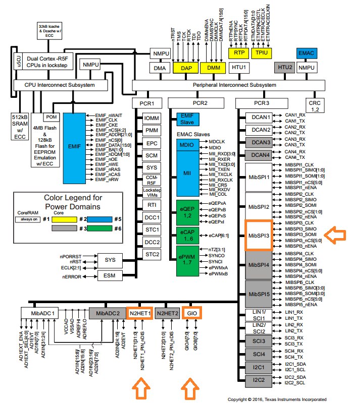
Matching the Hercules Controller with the DRV8711 Stepper Driver

I'm using a LaunchPad and a BoosterPack.

That's a double-edged sword. I don't have to make PCBs - but on the other hand I'm dependent on the TI boards for matching pins (always a bet when combining LaunchPads and BoosterPacks).

The DRV8711 BoosterPack is the driver for requirements. We need to be able to drive or read all of its pins.

I know the exercise has to be possible because someone at TI showed me a video of this combination ramping up a stepper motor.

So if at the end of the blog series this doesn't work, it's me.


Side note to self: this (found when writing the blog image ) Pulse Train Output application note from TI may contain most of the PWM code.

image

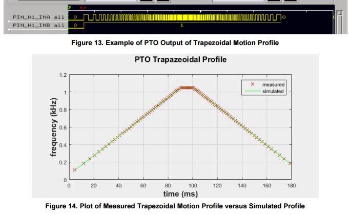
If that's true, it may be an unexpected windfall.

I was afraid to start programming the NHET subcontroller with the HET assembly language. It's been my weak point since as long as I work with the Hercules family.

I haven't checked the document in detail but it looks promising ...


... continuing with the:


DRV8711 BoosterPack pins

image


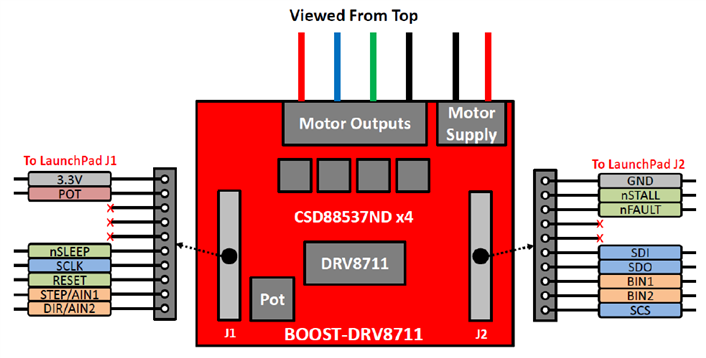
The critical ones are the SPI pins (SCLK, SDI, SDO, SCS) and the PWM pin (STEP/AIN1).

The green pins and DIR/AIN2 can be handled with any pin that's GIO capable.

3V3 and GND are standard, not to worry.

I don't need the potentiometer input and the BIN pins.


Hercules RM57 LaunchPad pins

Good news. A match for many. This is not that common with Hercules Launchpads. They defer often from the BoosterPack layout (deliberately not using the word standard here).


image

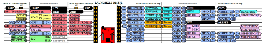
The match table below shows where I am confident and where more investigation is necessary.


BoosterPackFunctionRequirements for HerculesHeader 4
3.3V
nSLEEPtell driver to sleep (no current to the stepper coils)GIO out

AD1[17] or AD2[0]

SCLKSPI clockSPI clockMIBSPI3CLK
RESETreset driverGIO outGIOA[6]
STEP/AIN1PWM inputHET / PWM outNHET1[4]
DIR/AIN2motor directionGIO outNHET1[9]
GND
nSTALLis the motor stalled?GIO inNHET1[22]
nFAULTis the driver in error state?GIO inNHET1[[25] or MIBSPI3NCS[1]
SDISPI Slave in Master outSPI MOSIMIBSPI3SIMO
SDOSPI Slave out Master inSPI MISOMIBSPI6SOMI
SCSSPI chip select (active high !)SPI CSGIOB[2]


My main worry is the nSLEEP pin. I'll have to read the doco to see if I can render an analog input into a digital output.

I don't understand why this particular pin is used on the BoosterPack for a signal that has to be driven by the microcontroller.

On the BoosterPack standard, this is reserved for analog in signals. The pin above that is a generic IO pin. And its free. Why?


Related Blog
Part 1: Hardware Overview
Part 2: Stepper Controller and MSP430 Firmware
Part 3: SPI Commands and Pulse Control
Part 4: Analyse MSP430 PWM Step Signal
Part 5: Hercules RM57 Hardware Provisioning
Part 6: Hercules RM57 SPI
Part 7: HET Assembly Language Test
Part 8: HET Based Pulse Train Output
  • Sign in to reply
  • Jan Cumps
    Jan Cumps over 8 years ago

    I have SPI working on the Hercules.


    This is a capture of the same init sequence I captured earlier on on the MSP430:

    image


    Protocol Analysis:

    image


    Easiest job done. Now the high-end timer ...

    • Cancel
    • Vote Up 0 Vote Down
    • Sign in to reply
    • More
    • Cancel
  • Jan Cumps
    Jan Cumps over 8 years ago in reply to Jan Cumps

    ....  aand done.


    image

    • Cancel
    • Vote Up 0 Vote Down
    • Sign in to reply
    • More
    • Cancel
  • Jan Cumps
    Jan Cumps over 8 years ago

    It seems that I can't turn the ADC pin that's connected to nSLEEP as a GIO output. Except for the ADC event pin, the module isn't configurable as GIO.

    External event pin (ADEVT) programmable as general-purpose I/O

    That means that I'll have to hack the BoosterPack. The pin above the ADC is a GIO.

    image

    I've just double-checked with a meter that it isn't connected to anything.

    So I can put a bridge between J1 PIN 5 and 6 on the BoosterPack.

    Then I can drive the GIO pin high or low as needed. The ADC pin won't mind. It can have 3V3 without issues.


    I'll use a male pin header and hack that onto the connector pins. I can then use a jumper to make and break.

    • Cancel
    • Vote Up 0 Vote Down
    • Sign in to reply
    • More
    • Cancel
  • Jan Cumps
    Jan Cumps over 8 years ago
    SPI chip select (active high !)

    It should be possible to use a positive chip select with this functionality:

    image

    I can set exactly what CS pin of SPI3 is high or low during activation of transfer. Looks good...


    Correction: the CS is on GIOB pin 2. So I'll have to manually CS. No problem

    • Cancel
    • Vote Up 0 Vote Down
    • Sign in to reply
    • More
    • Cancel
element14 Community

element14 is the first online community specifically for engineers. Connect with your peers and get expert answers to your questions.

  • Members
  • Learn
  • Technologies
  • Challenges & Projects
  • Products
  • Store
  • About Us
  • Feedback & Support
  • FAQs
  • Terms of Use
  • Privacy Policy
  • Legal and Copyright Notices
  • Sitemap
  • Cookies

An Avnet Company © 2025 Premier Farnell Limited. All Rights Reserved.

Premier Farnell Ltd, registered in England and Wales (no 00876412), registered office: Farnell House, Forge Lane, Leeds LS12 2NE.

ICP 备案号 10220084.

Follow element14

  • X
  • Facebook
  • linkedin
  • YouTube