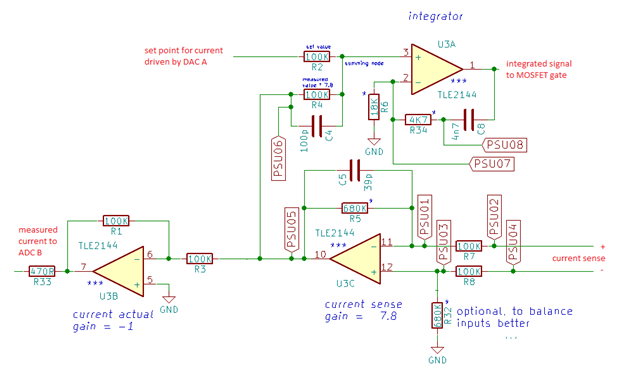
This blog documents investigates the feedback node of the electronic load that Robert Peter Oakes, jc2048 and Jan Cumps are designing. It's an important spot in the load's design. It measures the set point and the feedback from the output. When the output is driven to 0, it should be on a potential as close as possible to 0 V. On the first prototype it's -0.2 V. Not so much off, but the negative value influences our ADC measurements. This document checks how we can get this node to 0 V. |
Because this document is evolving, some comments below may be out of sync with the content. That's because the content is adapted based on the conversation.
The measurements taken here are based on the original design, without R32 in place and U3B + tied to ground.
The current sense side of R7 is connected to ground, and a variable negative voltage from 0 V down is applied to the current sense side of R8 to simulate current being sensed.
The circuit isn't complex. The set point is driven by a DAC. It's set to 0 for this test.
The second input to this node is OpAmp 3C. It has both inputs tied to ground so should theoretically have 0 V at the output.
On my board I measure a potential of -0.212V at the left side of R33.
I hope to get this closer to 0 V to ease the ADC a bit - its performance degrades with negative voltage at its inputs.
Like the other blogs for the electronic load, this is a working document that will be updated with findings from anyone who wants to chime in.
Behaviour at 0V


Top Comments
-

Jan Cumps
-
Cancel
-
Vote Up
+1
Vote Down
-
-
Sign in to reply
-
More
-
Cancel
-

Jan Cumps
in reply to Jan Cumps
-
Cancel
-
Vote Up
+1
Vote Down
-
-
Sign in to reply
-
More
-
Cancel
-

Jan Cumps
in reply to jc2048
-
Cancel
-
Vote Up
+1
Vote Down
-
-
Sign in to reply
-
More
-
Cancel
-

Jan Cumps
in reply to Jan Cumps
-
Cancel
-
Vote Up
+1
Vote Down
-
-
Sign in to reply
-
More
-
Cancel
-

Jan Cumps
in reply to Jan Cumps
-
Cancel
-
Vote Up
+1
Vote Down
-
-
Sign in to reply
-
More
-
Cancel
-

Jan Cumps
in reply to Jan Cumps
-
Cancel
-
Vote Up
+1
Vote Down
-
-
Sign in to reply
-
More
-
Cancel
-

jc2048
in reply to Jan Cumps
-
Cancel
-
Vote Up
+1
Vote Down
-
-
Sign in to reply
-
More
-
Cancel
-

Jan Cumps
in reply to Jan Cumps
-
Cancel
-
Vote Up
0
Vote Down
-
-
Sign in to reply
-
More
-
Cancel
-

Jan Cumps
in reply to Jan Cumps
-
Cancel
-
Vote Up
0
Vote Down
-
-
Sign in to reply
-
More
-
Cancel
-

jc2048
in reply to Jan Cumps
-
Cancel
-
Vote Up
0
Vote Down
-
-
Sign in to reply
-
More
-
Cancel
-

Jan Cumps
in reply to jc2048
-
Cancel
-
Vote Up
+1
Vote Down
-
-
Sign in to reply
-
More
-
Cancel
-

Jan Cumps
in reply to Jan Cumps
-
Cancel
-
Vote Up
+1
Vote Down
-
-
Sign in to reply
-
More
-
Cancel
Comment-

Jan Cumps
in reply to Jan Cumps
-
Cancel
-
Vote Up
+1
Vote Down
-
-
Sign in to reply
-
More
-
Cancel
Children