In the last blog post, I successfully built a battery-operated LoRaWAN-connected environmental sensor that measures temperature, humidity, barometric pressure and light intensity via an Omron evaluation module in the MKR form factor. The sensor power and code weren’t power-optimised, yet a projected battery life of one month was achievable.
The cost, however, was the lack of particulate monitoring as the MKR WAN 1310’s design lacks a 5V rail when operating off the battery input. This makes particulate monitors unhappy as they rely on 5V for an acceleration resistor or brushless DC fan to move air around and may even rely on it for their laser source. I also didn’t integrate any battery voltage sensing to reduce power consumption in the previous design and I feel that it is perhaps a good feature to have. I hate giving up on something I proposed to do and I did promise particulate monitoring, so I decided to knock this one out before moving onto the AI-side and front-end aspects.
Table of Contents
The Challenge of Providing 5V
As I mentioned in the introduction, particulate monitor sensors absolutely require 5V. The MKR WAN 1310’s architecture has a Li-Ion battery input which, due to the nature of the battery, can range from about 3.0V through to 4.2V. To keep all peripherals happy, there is a boost converter that steps the input up to 3.8V and a linear low-dropout regulator to cut this back to 3.3V for a smooth and clean voltage for the microcontroller and radio. Communication happens at 3.3V too. While it seems that this arrangement isn’t particularly special, a lot of care has been done in the design phase to choose components which are both small and highly efficient at a range of loads, helping the MKR WAN 1310 achieve rather wonderful standby current consumption results.
Part of the sacrifice with the design was the 5V rail. In some boards, the 5V rail may have just had the unregulated Li-Ion input on it, perhaps through an arbiter diode. The downside to that arrangement is some level of quiescent leakage, so it is not included on the boards. Nevertheless, a wandering 5V rail that depends on the battery voltage and never reaches 5V will never do!
The first thought, of course, is to whack a boost module in there to step-up the voltage. However, which one in particular and where should it be connected? Ideally it should be something efficient and on-hand. It may be tempting to connect it to 3.3V and take advantage of the onboard PMIC to handle battery charging and over-discharge protections. Upon further thought, while that would work, it isn’t necessarily in good form as it could make the 3.3V rail noisy, stress the existing components and reduce efficiency as multiple conversion stages are being chained together. Instead, it would be much better to take the input directly from the unregulated battery for best efficiency.
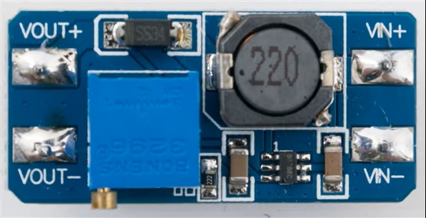
In the end, I decided to use an MT3608-based step-up module that I had characterised back in this 2018 RoadTest Review. This one is known to be decently efficient, but most importantly, had a decently low quiescent current consumption. While I could just whack one in, I decided to do one better …
The 5V rail is not needed at all times - only when making a measurement. What if we could power-down the converter when it’s not in use and save on most of the quiescent current? That would stretch our battery lifetime (possibly significantly). I thought about how this could be done - if I added an N-MOSFET on the low-side, I could switch the input power, but the MKR’s 3.3V output wouldn’t make for a particularly low Rds (unfortunately).

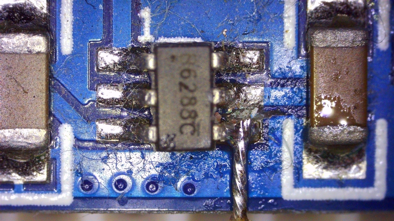
Examining the datasheet shows that the MT3608 has an enable pin with a 1.8V threshold. This pin isn’t broken out in this module, so a quick bit of work with a knife to cut the trace between Vin+ and EN was enough to reclaim the pin, then soldering a jumper wire to the pin allows the converter to be controlled without the fuss of an external MOSFET. This may result in slightly higher leakage, but it is still better than paying quiescent current 24/7 for a 5V rail that isn’t needed all the time!
The Particulate Monitor Sensor
I had purchased a pair of Sensirion SPS30 laser particulate monitor sensors a few years ago to replace one that had failed after its fan seized up while operating in harsh and unintended conditions, but never got around to using them. The sensors are great, but the fine-pitch connector is a bit of a pain. Luckily my purchase came with a wiring harness to loose ends, to which I crimped Dupont connector pins to.
Communications for the sensor was over I2C or UART, but the library seems only to support I2C by default. I opted to run a 3.3V bus to keep the MKR happy. This means I had to install external pull-up resistors to pull the bus up to 3.3V, opting for a random value from the parts bin in the 2.2kΩ-10kΩ range that would work adequately. As this wasn’t switched, there is the potential for several sources of quiescent current draw - from the SPS30’s I2C bus inputs themselves and leakage from those I2C inputs through to the 5V rail. In some cases, this “remnant voltage” can cause sensors to malfunction as it may violate their requirements for monotonic power-up/power-down waveforms on their voltage rails. I guess I’ll have to try this and see … otherwise the solution could get quite complex.
I could use the Omron dust and smoke sensor that would have originally been paired with the board in the previous section, but since that one relies on analog inputs, produces arbitrary counts and relies on a resistor “accelerator” that has a thermal mass and warm-up time, I decided the SPS30 would be a superior choice.
Measure Battery Voltage
Measuring the battery voltage is a simple task - just whack in a voltage divider and hook it up to an analog pin. To minimise the current consumption, I chose higher resistance values - 100kΩ+220kΩ in series. This also allows me to use most of the range of the ADC, but not all. I could get away with this somewhat since ultimate precision is not important - ideally a capacitor might also be good over the 220kΩ resistor to allow the switched-capacitor ADC to get a good sample without dragging the input down. One downside is that unfortunately, as I only had 5% resistors on-hand, I had to also calibrate this somewhat by adding an offset multiplier in the code.
The MKR WAN 1310 has a 12-bit capable ADC that is run in 10-bit “compatible” mode by default. I chose to run it at 12-bit, but then ended up truncating the result to 8-bits as transmission bandwidth was precious and ultimate precision was not the aim. I was hoping this would give a more accurate 8-bits, as often we know the “effective number of bits” is not the full number of output bits! The cost of this battery measurement? About 13.125uA in terms of current at 4.2V, which is not entirely insignificant compared to an MKR WAN 1310 on its own, but is perhaps negligible compared to the heavier consumption of other parts on the board.
Adding Solar Power, Keeping the Battery Happy
Just when you thought we couldn’t have any more voltages, we add solar power into the mix. Photovoltaic solar panels are a bit of an inconsistent beast - depending on the angle and intensity of the sun, the output voltage and current available, and hence the maximum power point changes. As a result, they don’t provide a stable source of power, but this is not necessarily too difficult to deal with. What is more important to realise is that modules are commonly made in “nominal” voltage ratings - 12V-system panels are common for smaller panels with a maximum voltage usually in the 16-19V range. Thus, we need to be able to handle this in some way.
Another issue now is that with the increased complexity and loads, there is a real danger of the battery becoming over-discharged over time, especially if something goes wrong with the power source and it remains unchecked for a while. In the other design, where every sensor is powered through the MKR board itself, there was no issue as the PMIC on the MKR WAN 1310 would cut-off the battery once it had reached its full discharge. In this one, we have a “dumb” voltage divider sipping current continuously, we have an MT3608 sipping its standby continuously as well, neither of which are switched by the PMIC on the MKR WAN 1310. Therefore, an external protection solution is needed.
Raiding my junk box again for cheap parts, a combination TP4056 single-cell lithium-ion battery charger seemingly configured for 1A with onboard DW01 and MOSFET for doing over-discharge protection. This is a rather “inefficient” linear charger, but sometimes we can afford this and the simplicity it brings. We will use this to arbitrate power from the battery to all loads and use it to charge the battery.
But wait - again, it is not as simple as plugging in a TP4056 to a solar panel since the TP4056 can only handle an absolute-maximum of 8V input (and that’s probably pushing it into overheat territory). Instead, this time, we need a buck converter to step down the solar input to about 5V for the TP4056.
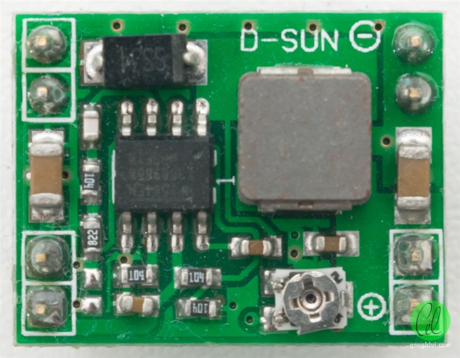
For this, I chose a MP1584 buck module as I had some on-hand - these are also pretty efficient and inexpensive. Hooking up a solar panel to one of these directly is not necessarily a recipe for happiness - in fact, depending on the panel you have available and the weather, it may well “hiccup” as it starts up, gets overloaded by the charger, then shuts down. The good news is that through these “hiccups”, the battery is still receiving some charge. The downside is that such hiccup operation is going to keep resetting the charger chip thus over-time protections and proper termination may not function as desired. However, if you’re using “salvaged” lithium-ion cells like I am, then perhaps this is not so important. In theory, if you didn’t mind “floating” your Li-Ion cells (and you really shouldn’t), you could set the buck to a safe 4.0V and leave it hooked to the cell … but at the cost of potentially shortening cell life and added quiescent current. You’d still likely need a DW01 and MOSFET combo to keep the cells from being over-discharged in the worst-case scenario.
Coding a Sketch and Updating the Parser
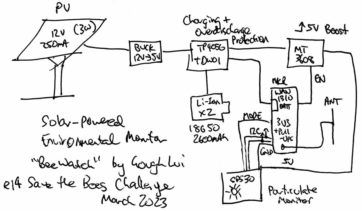
The block diagram for the system I’ve described so far looks like this:
We’re not done yet of course, we need a new sketch to run the SPS30. This is where I realised that The Things Network’s 30-second fair use airtime can be quite restrictive as the current sensor board already runs close to the limit by updating us once every four minutes. Adding additional particulate monitor measurements would only increase the payload size and thus increase the intervals between reports, making it less real-time. I could try shaving another two bytes off the current by reducing the precision in the barometric pressure measurement, but there is another way.
How about adding a second MKR WAN 1310? Yes … I managed to get some more MKR WAN 1310 boards. They’re not cheap, but the fair use policy limits apply per-device and not per-account, thus having a second device for particulate monitor functions means we can get another 30-seconds of airtime per day! Of course, if you’re on the free tier, you can only have a total of ten devices, so keep this in mind.
To get it working, I took my previous code and modified it to incorporate code from the sps30 library. At first, I just needed to see it print the values onto the serial console to be sure the I2C communications were all sweet:
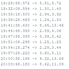
As the sensor is constantly getting powered on and off, I have to make sure to clean it every so often, so I keep a count of consecutive readings completed and run a cleaning cycle every 1000 readings. The code is as follows:
// SPS30 LoRaWAN by Gough Lui
// element14 Save-the-Bees Design Challenge - March 2023
// Free to use and repurpose - use at your own risk
// Configured for AU915 band-plan usage

#include <MKRWAN.h>
#include <sps30.h>
#include "ArduinoLowPower.h"

#define BATTMON A6
#define PWRCTL 5

LoRaModem modem;
// Uncomment if using the Murata chip as a module
// LoRaModem modem(Serial1);

#include "arduino_secrets.h"
// Please enter your sensitive data in the Secret tab or arduino_secrets.h
String appEui = SECRET_APP_EUI;
String appKey = SECRET_APP_KEY;

int cleancounter = 0;

void setup() {
  USBDevice.detach(); // No USB to save power
  //Serial.begin(115200);
  //delay(2000);
  analogReadResolution(12);
  pinMode(PWRCTL,OUTPUT);
  digitalWrite(PWRCTL,LOW);
  if (!modem.begin(AU915)) {
    //Serial.println("Failed to start module");
    while (1) {}
  };
  //Serial.print("Your module version is: ");
  //Serial.println(modem.version());
  //Serial.print("Your device EUI is: ");
  //Serial.println(modem.deviceEUI());
  modem.sendMask("ff000000f000ffff00020000");
  int connected = 0;
  while (!connected) {
    //Serial.println("Attempting to join network ...");
    connected = modem.joinOTAA(appEui, appKey);
  }
  modem.minPollInterval(60);
  modem.dataRate(5);   // switch to SF7
  modem.setPort(3);  // Set FPort Value to 3
}

void loop() {
  digitalWrite(PWRCTL,HIGH);
  delay(300); // Converter power-up + SPS30 power-up
  sensirion_i2c_init();
  sps30_probe();

  struct sps30_measurement m;
  char serial[SPS30_MAX_SERIAL_LEN];
  uint16_t data_ready;
  char packetBuffer[5];

  sps30_wake_up();
  sps30_start_measurement();
  delay(10000);

  while (sps30_read_data_ready(&data_ready) < 0) {
    delay(20);
  }
  if (sps30_read_measurement(&m) >= 0) {
    uint16_t pm25val = (uint16_t)(m.mc_2p5*100);
    uint16_t pm10val = (uint16_t)(m.mc_10p0*100);
    uint8_t battval = (uint8_t)(analogRead(BATTMON)>>4);
    memcpy(packetBuffer,&pm25val,2);
    memcpy(packetBuffer+2,&pm10val,2);
    memcpy(packetBuffer+4,&battval,1);
  }
  cleancounter = cleancounter + 1;
  if (cleancounter > 1000) {
    cleancounter = 0;
    sps30_start_manual_fan_cleaning();
    delay(10000);
  }
  sps30_stop_measurement();
  sps30_sleep();
  digitalWrite(PWRCTL,LOW); // shut-down 5V rail

  modem.beginPacket();
  modem.write(packetBuffer,5);
  modem.endPacket(false);
  delay(1000);
  if (modem.available()) {
    char rcv[64];
    int i = 0;
    while (modem.available()) {
      rcv[i++] = (char)modem.read();
    }
  }
  LowPower.deepSleep(180000); // 3 minute sleep
}
The binary data format focuses on providing two uint16_t values corresponding to PM2.5 concentration in 0.01 ug/m^2 concentration units, and one uint8_t value corresponding to the ADC measurement from the battery voltage divider. I rely on my Javascript parser code to convert this to a voltage for easier “digestion”:
function Decoder(bytes, port) {
   var decoded = {};
   if (port === 2) {
     decoded.temp = ((bytes[3]*256.0)+bytes[2])/100.0;
     decoded.humidity = ((bytes[1]*256.0)+bytes[0])/100.0;
     decoded.pressure = ((bytes[7]*16777216.0)+(bytes[6]*65536.0)+(bytes[5]*256.0)+bytes[4])/1000.0;
     decoded.lux = ((bytes[9]*256.0)+bytes[8]);
     decoded.time=Math.round(new Date().getTime()/1000);
   }
   if (port === 3) {
     decoded.pm25 = ((bytes[1]*256.0)+bytes[0])/100.0;
     decoded.pm10 = ((bytes[3]*256.0)+bytes[2])/100.0;
     decoded.voltage = bytes[4]/256.0*1.455*3.3*1.0115;
     decoded.time=Math.round(new Date().getTime()/1000);
   }
   return decoded;
}
With this decoder, now my “buzzmehappy” application returns both environmental monitors within the same stream, choosing which algorithm to apply based on Fport parameters.

With this I now have particulate monitor readings. While the SPS30 is capable of providing 1um, 4um and average size readings as well, I don’t think it makes sense to transmit them, instead focusing only on the most important readings. This is because even with a 5-byte LoRaWAN payload, we are limited to about 3-minute transmit intervals under good radio conditions, and less if the conditions are worse. The less data, the better!
By the end of this, I realised if I took the code from before for backing-up and restoring the keys from the modem, it is theoretically possible to have one MKR WAN 1310 behave as several devices at the same time by quickly reloading a unique UID+key+Fcnt set into the modem before transmitting and then waiting for the RX windows to pass before reloading the next set. If you did that, then perhaps you won’t need to have more than one MKR WAN 1310 for such experiments … but I like to have more so I can develop on a board while another is doing its long-term operation tests. But please don’t abuse this!
The Breadboard Build and Power Consumption
It was a challenge to squeeze all of this onto a breadboard and by the end, I had to cheat with some double-sided tape to hold the battery holders to the breadboard surface. I quite like the result - the green wires are all because that is the only roll of solid-core wire I have on hand. It’s the same reel that I had since I was an undergraduate student. During teaching, we forced students to adhere to strict colour coding for ease of debugging - but in the privacy of my own home, I’m happy to be “all-green” - and accept responsibility for any accidents which may otherwise happen. It’s also nice to have a crimp and pins for the Dupont Wire connectors - this way I can make my own wire connections for the batteries and JST to the breadboard bus.
While it is possible to consolidate the Omron sensor back into this design, I feel that there is a nice positive in terms of LoRaWAN reporting frequency by having them separate. I could bus-together the batteries so that both can benefit from solar charging, but perhaps that is something for the future.
To understand how long such a set-up would last on battery and whether solar power was absolutely necessary, I decided to repeat the same type of measurements with the Keithley 2450 SMU as I did with the previous design. Not unexpectedly, the power consumption is greater, but perhaps still less than I had anticipated.

The analysis shows the peak current is at about 150mA when the switching converter for 5V starts up, with the fan in the SPS30 keeping the draw steady at about 92mA. Once completed, I turn off the particulate monitor and start the LoRaWAN TX which costs about 134mA peak, before it dies down into a wait and a small blip for RX. Deep sleep is a pleasant 327uA! Based on integrating for the whole cycle, it seems the pair of 18650 cells I salvaged from an old laptop will last 37 days on a charge which is pretty amazing.
While the board itself has provision for the solar panel input, I have yet to grab my spare solar panel out of storage to make use of it. That’s fine, because the fully-charged pair of 18650 cells need to discharge a bit to prove the battery charging functionality which will take a while. In the meantime, let’s operate battery only for now …
Conclusion
In the spirit of not giving up, I now finally have a particulate monitor sensor on LoRaWAN as well, courtesy of a second MKR WAN 1310 I’ve managed to get my hands on. By doing so, I get another 30s per day of “fair-use” airtime, ensuring we get timely particulate monitor readings. Because of increased power consumption, solar power is advisable, but with careful optimisation of all the power conversion steps and the duty cycling of only taking a reading every three minutes, a pair of 18650 cells can now run the unit for more than a month. Absolutely amazing. For now, while it is solar-ready, it’s not running on solar primarily because I still have to grab a spare panel and the battery needs to discharge a bit to prove it is being charged by solar.
Will I go back to the idea of dealing with the Nicla Vision or will I move on to putting these boards outside for some “field tests”? I guess we’ll have to wait for the next blog to find out!
[[BeeWatch Blog Index]]
- Blog 1: README.TXT
- Blog 2: Unboxing the Kit
- Blog 3: LoRa vs. LoRaWAN & Getting Started with MKR WAN 1310
- Blog 4: LoRaWAN Gateway Set-Up & MKR WAN 1310 Quirks
- Blog 5: Power, State Saving, Using Sensors & Battery
- Blog 6: Particulate Monitoring & Solar Power Input
- Blog 7: Powered by the Sun & Initial Data
- Blog 8: Getting Started with Nicla Vision
- Blog 9: Nicla Vision IR ToF & Audio Sensing, Data Dump
- Blog 10: Nicla Vision Power, Saving B’s & Dashboard Woes
- Blog 11: Summary Conclusion

