


Project Roadmap
Part 1 - Experimental Smart Assistive Platform for Elderly and Disabled People
Part 3 - Wireless Command and H-Bridge Direct Drive
Part 4 - Introducing Autonomous Line Following (TCRT5000)
Part 5 - Non-Contact Proactive Shielding (HC-SR04 Range Finder)
Part 6 - Strict Priority Hierarchy with Tactile Mechanical Bumpers
Part 7 - Mobile Robot Control and Live Video Streaming
- Do not call pinMode(pin, OUTPUT) for your chosen PWM pin.
- Call analogWrite(pin, value) directly in your code.
- The value ranges from 0 (always off) to 255 (always on).
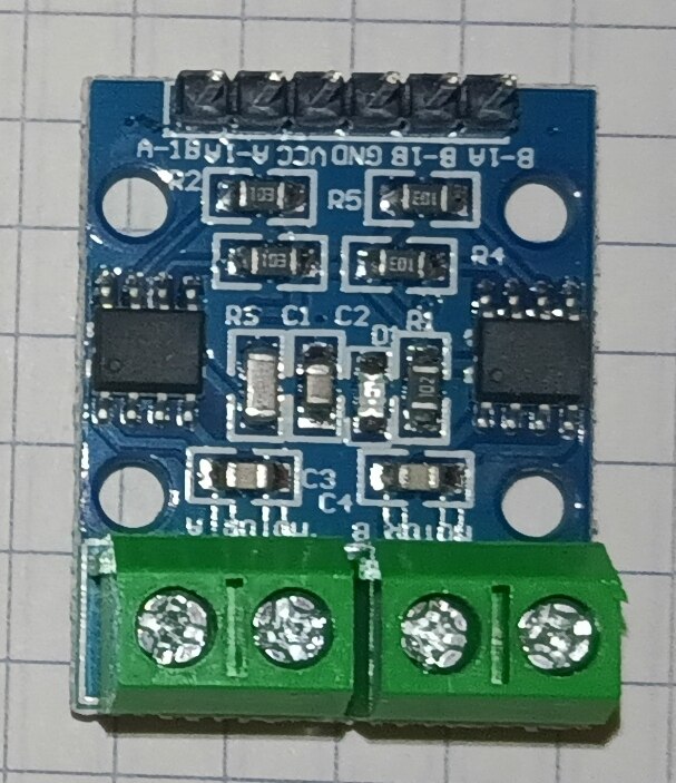
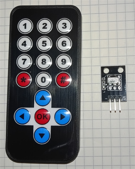
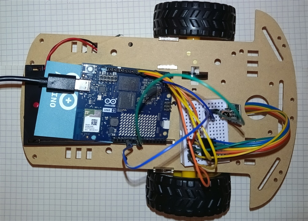
Here is the circuit connection and pin configuration guide for setting up your Arduino board with the L9110S motor driver, IR receiver, and power system.
Pin Mapping Table
| Component | Component Pin | Arduino UNO Q Pin | Notes / Description |
| L9110S Motor Driver | A-1A / A-1B |
Pin 5 (PWM) | Motor A Direction & Speed |
A-1B / A-2A |
Pin 6 (PWM) | Motor A Direction & Speed | |
B-1A / B-1B |
Pin 9 (PWM) | Motor B Direction & Speed | |
B-1B / B-2A |
Pin 10 (PWM) | Motor B Direction & Speed | |
VCC |
External Power (+) | 6V - 12V (Battery pack) | |
GND |
Common Ground (-) | Shared GND with Arduino | |
| IR Receiver | OUT / DATA |
Pin 2 | Signal line (INPUT_PULLUP) |
VCC |
5V / 3.3V | Logic power supply | |
GND |
Common Ground (-) | Shared GND with Arduino |
This Arduino sketch implements a complete control system for a two-wheeled mobile robot managed via an Infrared (IR) remote. It decodes custom IR timing signals, controls DC motors using an L9110S H-bridge driver, provides visual status updates via onboard RGB LEDs, and displays directional arrows on an 8x13 LED matrix.
Key Code Sections
1. Libraries and Hardware Definitions
Imports necessary libraries for the LED matrix and assigns GPIO pins for the L9110S motor driver, IR receiver, and motor speed parameters.
#include <Arduino.h>
#include <Arduino_LED_Matrix.h>   // Library for the 8x13 LED matrix

Arduino_LED_Matrix matrix; // Initialize the large LED matrix

// L9110S Motor Driver Pins on Arduino UNO Q
const int MOTOR_PIN_A1 = 5;
const int MOTOR_PIN_A2 = 6;
const int MOTOR_PIN_B1 = 9;
const int MOTOR_PIN_B2 = 10;

// Infrared Receiver Pin (Configured with PULLUP)
const int IR_RECEIVE_PIN = 2;

// Motor speed (Scale 0-255 for Arduino analogWrite)
const int MOTOR_SPEED = 200;
2. LED Matrix Graphics Arrays
Defines 104-element arrays (8x13 display) storing grayscale values from 0 (OFF) to 7 (max brightness). These pre-rendered graphics represent directional arrows (Up, Down, Left, Right) and an empty frame for stopping.
const uint8_t FRAME_SIZE = 8 * 13; // 104 pixels for the LED matrix

// Example: Arrow Up Array
uint8_t arrow_up[FRAME_SIZE] = {
    0, 0, 0, 0, 0, 0, 7, 0, 0, 0, 0, 0, 0,
    0, 0, 0, 0, 0, 7, 7, 7, 0, 0, 0, 0, 0,
    0, 0, 0, 0, 7, 7, 7, 7, 7, 0, 0, 0, 0,
    0, 0, 0, 7, 7, 0, 7, 0, 7, 7, 0, 0, 0,
    0, 0, 0, 0, 0, 0, 7, 0, 0, 0, 0, 0, 0,
    0, 0, 0, 0, 0, 0, 7, 0, 0, 0, 0, 0, 0,
    0, 0, 0, 0, 0, 0, 7, 0, 0, 0, 0, 0, 0,
    0, 0, 0, 0, 0, 0, 7, 0, 0, 0, 0, 0, 0
};

uint8_t stop_icon[FRAME_SIZE] = { 0 };
3. Onboard RGB LED Helper Functions
Provides utility functions to control status indicator LEDs. set_led3_color uses analog PWM values for smooth color mixing, while set_led4_color handles active-LOW digital switching.
void set_led3_color(int r, int g, int b) {
  analogWrite(LED3_R, r);
  analogWrite(LED3_G, g);
  analogWrite(LED3_B, b);
}

void set_led4_color(bool r, bool g, bool b) {
  digitalWrite(LED4_R, r ? LOW : HIGH);
  digitalWrite(LED4_G, g ? LOW : HIGH);
  digitalWrite(LED4_B, b ? LOW : HIGH);
}
4. Low-Level IR Signal Decoder (readElecrowIR)
Implements custom pulse-width decoding for the Elecrow IR protocol without relying on standard IR libraries. It measures microsecond pulse durations, reconstructs 32 bits (4 bytes) of data, and validates signal integrity using a bitwise checksum (data + data == 0xFF).
long readElecrowIR() {
  int count = 0;

  // 1. Wait for leading LOW pulse
  while (digitalRead(IR_RECEIVE_PIN) == LOW && count < 200) {
    count++;
    delayMicroseconds(60);
  }
  if (count >= 200) return -1;

  // 2. Wait for leading HIGH space
  count = 0;
  while (digitalRead(IR_RECEIVE_PIN) == HIGH && count < 80) {
    count++;
    delayMicroseconds(60);
  }
  if (count >= 80) return -1;

  // 3. Read 32 bits of payload data
  int idx = 0, cnt = 0;
  byte data[4] = {0, 0, 0, 0};

  for (int i = 0; i < 32; i++) {
    count = 0;
    while (digitalRead(IR_RECEIVE_PIN) == LOW && count < 15) {
      count++;
      delayMicroseconds(60);
    }

    count = 0;
    while (digitalRead(IR_RECEIVE_PIN) == HIGH && count < 40) {
      count++;
      delayMicroseconds(60);
    }

    if (count > 8) {
      data[idx] |= (1 << cnt); // Store logical '1'
    }

    if (cnt == 7) { cnt = 0; idx++; } else { cnt++; }
  }

  // 4. Checksum verification
  if ((byte)(data[0] + data[1]) == 0xFF && (byte)(data[2] + data[3]) == 0xFF) {
    return data[2]; // Return valid command byte
  }

  return -1;
}
5. Motor Control and Command Execution
driveMotors sends PWM values directly to the driver pins. executeCommand maps hex command codes (e.g., 0x18 for forward) to corresponding motor movements, LED status colors, and matrix graphics.
void driveMotors(int a1, int a2, int b1, int b2) {
  analogWrite(MOTOR_PIN_A1, a1);
  analogWrite(MOTOR_PIN_A2, a2);
  analogWrite(MOTOR_PIN_B1, b1);
  analogWrite(MOTOR_PIN_B2, b2);
}

void executeCommand(byte command) {
  switch (command) {
    case 0x18: // Up Arrow - Forward
      driveMotors(0, MOTOR_SPEED, 0, MOTOR_SPEED);
      set_led4_color(false, true, false);
      set_led3_color(0, 200, 0);
      matrix.draw(arrow_up);
      break;
    case 0x08: // Left Arrow - Turn Left
      driveMotors(MOTOR_SPEED, 0, 0, MOTOR_SPEED);
      set_led4_color(false, false, true);
      set_led3_color(0, 0, 200);
      matrix.draw(arrow_left);
      break;
    default: // Stop on unassigned keys
      driveMotors(0, 0, 0, 0);
      set_led4_color(false, false, false);
      set_led3_color(0, 0, 0);
      matrix.draw(stop_icon);
      break;
  }
}
6. System Setup and Main Loop (setup & loop)
Configures input pins with internal pull-ups, initializes the display in 3-bit grayscale mode, and continuously polls the IR pin. The loop includes a fail-safe that stops the motors if no active transmission is detected.
void setup() {
  Serial.begin(115200);
  pinMode(IR_RECEIVE_PIN, INPUT_PULLUP); // Enable internal pull-up

  pinMode(LED4_R, OUTPUT);
  pinMode(LED4_G, OUTPUT);
  pinMode(LED4_B, OUTPUT);

  matrix.begin();
  matrix.setGrayscaleBits(3); // Enable 8-level brightness
  matrix.clear();
}

void loop() {
  if (digitalRead(IR_RECEIVE_PIN) == HIGH) {
    long result = readElecrowIR();
    if (result != -1) {
      lastCommand = (byte)result;
    }
  }

  // Safety mechanism: Stop motors if no IR signal is being transmitted
  if (digitalRead(IR_RECEIVE_PIN) == LOW) {
    driveMotors(0, 0, 0, 0);
  } else {
    executeCommand(lastCommand);
  }

  delay(10);
}#include <Arduino.h>
#include <Arduino_LED_Matrix.h> // Library for the 8x13 LED matrix
Arduino_LED_Matrix matrix; // Initialize the large LED matrix
// L9110S Motor Driver Pins on Arduino UNO Q
const int MOTOR_PIN_A1 = 5;
const int MOTOR_PIN_A2 = 6;
const int MOTOR_PIN_B1 = 9;
const int MOTOR_PIN_B2 = 10;
// Infrared Receiver Pin (Configured with PULLUP just like the manufacturer's code)
const int IR_RECEIVE_PIN = 2;
// Motor speed (Scale 0-255 for Arduino analogWrite)
const int MOTOR_SPEED = 200;
// Variable to store the last successfully decoded command
byte lastCommand = 0;
const uint8_t FRAME_SIZE = 8 * 13; // 104 pixels for the LED matrix
// --- LED MATRIX ARROW ARRAYS (Brightness levels 0-7) ---
uint8_t arrow_up[FRAME_SIZE] = {
0, 0, 0, 0, 0, 0, 7, 0, 0, 0, 0, 0, 0,
0, 0, 0, 0, 0, 7, 7, 7, 0, 0, 0, 0, 0,
0, 0, 0, 0, 7, 7, 7, 7, 7, 0, 0, 0, 0,
0, 0, 0, 7, 7, 0, 7, 0, 7, 7, 0, 0, 0,
0, 0, 0, 0, 0, 0, 7, 0, 0, 0, 0, 0, 0,
0, 0, 0, 0, 0, 0, 7, 0, 0, 0, 0, 0, 0,
0, 0, 0, 0, 0, 0, 7, 0, 0, 0, 0, 0, 0,
0, 0, 0, 0, 0, 0, 7, 0, 0, 0, 0, 0, 0
};
uint8_t arrow_down[FRAME_SIZE] = {
0, 0, 0, 0, 0, 0, 7, 0, 0, 0, 0, 0, 0,
0, 0, 0, 0, 0, 0, 7, 0, 0, 0, 0, 0, 0,
0, 0, 0, 0, 0, 0, 7, 0, 0, 0, 0, 0, 0,
0, 0, 0, 0, 0, 0, 7, 0, 0, 0, 0, 0, 0,
0, 0, 0, 7, 7, 0, 7, 0, 7, 7, 0, 0, 0,
0, 0, 0, 0, 7, 7, 7, 7, 7, 0, 0, 0, 0,
0, 0, 0, 0, 0, 7, 7, 7, 0, 0, 0, 0, 0,
0, 0, 0, 0, 0, 0, 7, 0, 0, 0, 0, 0, 0
};
uint8_t arrow_left[FRAME_SIZE] = {
0, 0, 0, 0, 7, 0, 0, 0, 0, 0, 0, 0, 0,
0, 0, 0, 7, 7, 0, 0, 0, 0, 0, 0, 0, 0,
0, 0, 7, 7, 7, 7, 7, 7, 7, 7, 7, 7, 7,
0, 7, 7, 7, 7, 7, 7, 7, 7, 7, 7, 7, 7,
0, 7, 7, 7, 7, 7, 7, 7, 7, 7, 7, 7, 7,
0, 0, 7, 7, 7, 7, 7, 7, 7, 7, 7, 7, 7,
0, 0, 0, 7, 7, 0, 0, 0, 0, 0, 0, 0, 0,
0, 0, 0, 0, 7, 0, 0, 0, 0, 0, 0, 0, 0
};
uint8_t arrow_right[FRAME_SIZE] = {
0, 0, 0, 0, 0, 0, 0, 0, 7, 0, 0, 0, 0,
0, 0, 0, 0, 0, 0, 0, 0, 7, 7, 0, 0, 0,
7, 7, 7, 7, 7, 7, 7, 7, 7, 7, 7, 0, 0,
7, 7, 7, 7, 7, 7, 7, 7, 7, 7, 7, 7, 0,
7, 7, 7, 7, 7, 7, 7, 7, 7, 7, 7, 7, 0,
7, 7, 7, 7, 7, 7, 7, 7, 7, 7, 7, 0, 0,
0, 0, 0, 0, 0, 0, 0, 0, 7, 7, 0, 0, 0,
0, 0, 0, 0, 0, 0, 0, 0, 7, 0, 0, 0, 0
};
uint8_t stop_icon[FRAME_SIZE] = { 0 };
// --- ONBOARD RGB LED CONTROL FUNCTIONS ---
void set_led3_color(int r, int g, int b) {
analogWrite(LED3_R, r);
analogWrite(LED3_G, g);
analogWrite(LED3_B, b);
}
void set_led4_color(bool r, bool g, bool b) {
digitalWrite(LED4_R, r ? LOW : HIGH);
digitalWrite(LED4_G, g ? LOW : HIGH);
digitalWrite(LED4_B, b ? LOW : HIGH);
}
// IR decoding function based exactly on Elecrow's logic and timing
long readElecrowIR() {
int count = 0;
// 1. Wait for the leading LOW pulse
while (digitalRead(IR_RECEIVE_PIN) == LOW && count < 200) {
count++;
delayMicroseconds(60);
}
if (count >= 200) return -1;
// 2. Wait for the leading HIGH space
count = 0;
while (digitalRead(IR_RECEIVE_PIN) == HIGH && count < 80) {
count++;
delayMicroseconds(60);
}
if (count >= 80) return -1;
// 3. Read 32 bits of payload data
int idx = 0;
int cnt = 0;
byte data[4] = {0, 0, 0, 0};
for (int i = 0; i < 32; i++) {
count = 0;
while (digitalRead(IR_RECEIVE_PIN) == LOW && count < 15) {
count++;
delayMicroseconds(60);
}
count = 0;
while (digitalRead(IR_RECEIVE_PIN) == HIGH && count < 40) {
count++;
delayMicroseconds(60);
}
// If the HIGH pulse duration was long (count > 8), register bit as 1
if (count > 8) {
data[idx] |= (1 << cnt);
}
if (cnt == 7) {
cnt = 0;
idx++;
} else {
cnt++;
}
}
// 4. Check checksum integrity (matches Elecrow's condition: data+data==0xFF)
if ((byte)(data[0] + data[1]) == 0xFF && (byte)(data[2] + data[3]) == 0xFF) {
return data[2]; // Returns the valid command byte
}
return -1;
}
void driveMotors(int a1, int a2, int b1, int b2) {
// Omit pinMode() in setup to keep PWM functional on the UNO Q Zephyr core
analogWrite(MOTOR_PIN_A1, a1);
analogWrite(MOTOR_PIN_A2, a2);
analogWrite(MOTOR_PIN_B1, b1);
analogWrite(MOTOR_PIN_B2, b2);
}
void executeCommand(byte command) {
switch (command) {
case 0x18: // Up Arrow - Forward
driveMotors(0, MOTOR_SPEED, 0, MOTOR_SPEED);
set_led4_color(false, true, false);
set_led3_color(0, 200, 0);
matrix.draw(arrow_up);
break;
case 0x08: // Left Arrow - Turn Left
driveMotors(MOTOR_SPEED, 0, 0, MOTOR_SPEED);
set_led4_color(false, false, true);
set_led3_color(0, 0, 200);
matrix.draw(arrow_left);
break;
case 0x5A: // Right Arrow - Turn Right
driveMotors(0, MOTOR_SPEED, MOTOR_SPEED, 0);
set_led4_color(false, false, true);
set_led3_color(0, 0, 200);
matrix.draw(arrow_right);
break;
case 0x52: // Down Arrow - Backward
driveMotors(MOTOR_SPEED, 0, MOTOR_SPEED, 0);
set_led4_color(true, false, false);
set_led3_color(200, 0, 0);
matrix.draw(arrow_down);
break;
default:
driveMotors(0, 0, 0, 0); // Stop for unassigned keys
set_led4_color(false, false, false);
set_led3_color(0, 0, 0);
matrix.draw(stop_icon);
break;
}
}
void setup() {
Serial.begin(115200);
// Enable internal pull-up resistor (Equivalent to Pin.PULL_UP in MicroPython)
pinMode(IR_RECEIVE_PIN, INPUT_PULLUP);
Serial.println("Elecrow IR Decoder for Arduino UNO Q Ready.");
pinMode(LED4_R, OUTPUT); pinMode(LED4_G, OUTPUT); pinMode(LED4_B, OUTPUT);
set_led3_color(0, 0, 0);
set_led4_color(false, false, false);
matrix.begin();
matrix.setGrayscaleBits(3);
matrix.clear();
}
void loop() {
// Main loop logic translated 1:1 from the manufacturer's MicroPython code
if (digitalRead(IR_RECEIVE_PIN) == HIGH) {
long result = readElecrowIR();
if (result != -1) {
lastCommand = (byte)result;
Serial.print("Retrieve key: 0x");
Serial.println(lastCommand, HEX);
}
}
// Safety and control: if the IR pin is HIGH (no transmission), stop the robot.
// Otherwise, continue executing the last received command.
if (digitalRead(IR_RECEIVE_PIN) == LOW) {
driveMotors(0, 0, 0, 0); // Stop
} else {
executeCommand(lastCommand);
}
delay(10); // Small delay for main loop stabilization
}