


Project Roadmap
Part 1 - Experimental Smart Assistive Platform for Elderly and Disabled People
Part 3 - Wireless Command and H-Bridge Direct Drive
Part 4 - Introducing Autonomous Line Following (TCRT5000)
Part 5 - Non-Contact Proactive Shielding (HC-SR04 Range Finder)
Part 6 - Strict Priority Hierarchy with Tactile Mechanical Bumpers
Part 7 - Mobile Robot Control and Live Video Streaming
Manual driving is limited by line-of-sight. To implement autonomous navigation, we integrate dual Infrared Line-Tracking Sensors (TrackingPin_L and TrackingPin_R). These sensors output binary feedback depending on whether they detect a highly reflective light floor or a non-reflective dark path.To allow transitioning between manual piloting and automatic tracking, we establish a State Machine using a RobotMode enumeration. Pressing a designated toggle button (0x1C or "OK") alternates the core operating architecture.
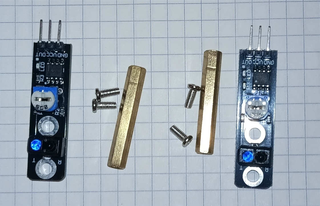
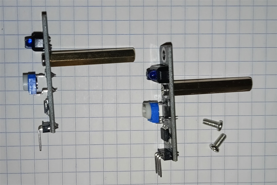
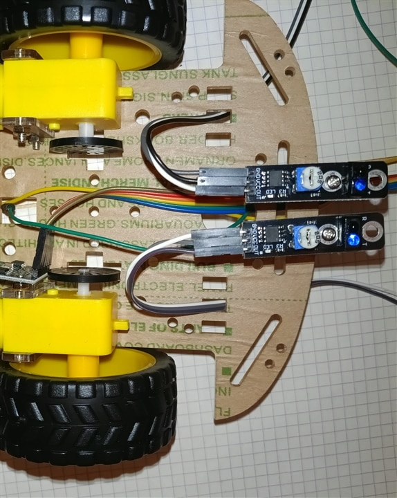
Hardware Wiring Diagram
Each IR tracking sensor module typically uses a 3-pin or 4-pin breakout board:
1. Left Tracking Sensor (TRACKING_PIN_L)
-
VCC Pin: Connects to 5V (or 3.3V, depending on sensor specifications).
-
GND Pin: Connects to GND (Ground).
-
OUT / Signal Pin: Connects to Analog Pin
A2.
2. Right Tracking Sensor (TRACKING_PIN_R)
-
VCC Pin: Connects to 5V (or 3.3V).
-
GND Pin: Connects to GND (Ground).
-
OUT / Signal Pin: Connects to Analog Pin
A3.
Pin Mapping Summary
| Sensor Component | Module Pin | Arduino UNO Q Pin | Wire Function |
| Left Sensor | VCC | 5V | Power supply |
| GND | GND | Common ground | |
| OUT / DO | A2 | Left line detection signal | |
| Right Sensor | VCC | 5V | Power supply |
| GND | GND | Common ground | |
| OUT / DO | A3 | Right line detection signal |
Electrical Notes
-
Internal Pull-Ups: The code configures the pins using
pinMode(A2, INPUT_PULLUP)andpinMode(A3, INPUT_PULLUP). This activates the microcontroller's built-in pull-up resistors, keeping the signal high by default and stabilizing digital state reads (HIGHvsLOW). -
Digital Reading: Although
A2andA3are labeled as analog input pins on the Arduino header, thedigitalRead()function processes them as standard digital binary inputs (returning0or1).
Here is the breakdown of the C code components responsible for line tracking (sensor reading, pin configuration, and autonomous navigation logic).
Line Tracking Code Snippets
1. Sensor Pin Definitions
The line tracking module uses two IR reflectance sensors connected to analog pins A2 (Left) and A3 (Right).
// Infrared Receiver and Tracking Sensor Pins
const int TRACKING_PIN_L = A2; // Left tracking sensor
const int TRACKING_PIN_R = A3; // Right tracking sensor

// Autonomous navigation speed threshold
const int TRACK_SPEED = 160;
2. Pin Configuration in setup()
In setup(), the sensor pins are initialized as inputs with internal pull-up resistors enabled (INPUT_PULLUP) to ensure stable digital reads.
void setup() {
  // Configure line tracking sensor pins as inputs with internal pull-ups
  pinMode(TRACKING_PIN_L, INPUT_PULLUP);
  pinMode(TRACKING_PIN_R, INPUT_PULLUP);
}
3. Operational Mode Toggle (MODE_AUTONOMOUS)
Pressing the OK button (0x1C) on the IR remote toggles between manual IR driving mode and autonomous line-following mode.
case 0x1C: // OK Button on IR Remote
  if (currentMode == MODE_MANUAL) {
    currentMode = MODE_AUTONOMOUS;
    Serial.println("Mode changed: AUTONOMOUS");
  } else {
    currentMode = MODE_MANUAL;
    driveMotors(0, 0, 0, 0); // Stop motors immediately on switch
    Serial.println("Mode changed: MANUAL");
  }
  lastCommand = 0;
  delay(500);
  break;
4. Sensor Reading & Differential Motor Control Loop
Inside loop(), when currentMode == MODE_AUTONOMOUS, the system reads the digital state of both line sensors, combines them into a binary state value (trackState), and adjusts motor outputs accordingly.
else if (currentMode == MODE_AUTONOMOUS) {
  // 1. Read individual sensor pin states (HIGH / LOW)
  int trackL = digitalRead(TRACKING_PIN_L);
  int trackR = digitalRead(TRACKING_PIN_R);

  // 2. Combine signals into a 2-bit state variable (0 to 3)
  // Bit 1 = Left Sensor, Bit 0 = Right Sensor
  int trackState = (trackL * 2) + trackR;

  // 3. Differential steering logic
  switch (trackState) {
    case 0:
      // Both sensors off-line -> Stop
      driveMotors(0, 0, 0, 0);
      break;
    case 1:
      // Right sensor on line -> Turn Right
      driveMotors(0, TRACK_SPEED, TRACK_SPEED, 0);
      break;
    case 2:
      // Left sensor on line -> Turn Left
      driveMotors(TRACK_SPEED, 0, 0, TRACK_SPEED);
      break;
    case 3:
      // Both sensors centered on line -> Drive Forward
      driveMotors(0, TRACK_SPEED, 0, TRACK_SPEED);
      break;
  }
  delay(10); // Short delay to stabilize sensor polling rate
}
Logic Summary
| trackL | trackR | trackState | Action | Description |
0 (LOW) |
0 (LOW) |
0 |
Stop | Line lost or end of track |
0 (LOW) |
1 (HIGH) |
1 |
Turn Right | Vehicle drifted left; right wheel drives forward, left reverses |
1 (HIGH) |
0 (LOW) |
2 |
Turn Left | Vehicle drifted right; left wheel drives forward, right reverses |
1 (HIGH) |
1 (HIGH) |
3 |
Move Forward | Both sensors detect the track; vehicle drives straight ahead |
#include <Arduino.h>
#include <Arduino_LED_Matrix.h> // Library for the 8x13 LED matrix

Arduino_LED_Matrix matrix; // Initialize LED matrix object

// L9110S Motor Driver Pins
const int MOTOR_PIN_A1 = 5;
const int MOTOR_PIN_A2 = 6;
const int MOTOR_PIN_B1 = 9;
const int MOTOR_PIN_B2 = 10;

// Infrared Receiver and Tracking Sensor Pins
const int IR_RECEIVE_PIN = 2;
const int TRACKING_PIN_L = A2;
const int TRACKING_PIN_R = A3;

enum RobotMode {
  MODE_MANUAL,
  MODE_AUTONOMOUS
};

RobotMode currentMode = MODE_MANUAL;

// Speed settings
const int MOTOR_SPEED = 200;
const int TRACK_SPEED = 160;

byte lastCommand = 0;

// LED Matrix Frame Buffer Size (104 pixels)
const uint8_t FRAME_SIZE = 8 * 13;

// --- LED MATRIX ARROW & ICON ARRAYS (Brightness levels 0-7) ---
uint8_t arrow_up[FRAME_SIZE] = {
    0, 0, 0, 0, 0, 0, 7, 0, 0, 0, 0, 0, 0,
    0, 0, 0, 0, 0, 7, 7, 7, 0, 0, 0, 0, 0,
    0, 0, 0, 0, 7, 7, 7, 7, 7, 0, 0, 0, 0,
    0, 0, 0, 7, 7, 0, 7, 0, 7, 7, 0, 0, 0,
    0, 0, 0, 0, 0, 0, 7, 0, 0, 0, 0, 0, 0,
    0, 0, 0, 0, 0, 0, 7, 0, 0, 0, 0, 0, 0,
    0, 0, 0, 0, 0, 0, 7, 0, 0, 0, 0, 0, 0,
    0, 0, 0, 0, 0, 0, 7, 0, 0, 0, 0, 0, 0
};

uint8_t arrow_down[FRAME_SIZE] = {
    0, 0, 0, 0, 0, 0, 7, 0, 0, 0, 0, 0, 0,
    0, 0, 0, 0, 0, 0, 7, 0, 0, 0, 0, 0, 0,
    0, 0, 0, 0, 0, 0, 7, 0, 0, 0, 0, 0, 0,
    0, 0, 0, 0, 0, 0, 7, 0, 0, 0, 0, 0, 0,
    0, 0, 0, 7, 7, 0, 7, 0, 7, 7, 0, 0, 0,
    0, 0, 0, 0, 7, 7, 7, 7, 7, 0, 0, 0, 0,
    0, 0, 0, 0, 0, 7, 7, 7, 0, 0, 0, 0, 0,
    0, 0, 0, 0, 0, 0, 7, 0, 0, 0, 0, 0, 0
};

uint8_t arrow_left[FRAME_SIZE] = {
    0, 0, 0, 0, 7, 0, 0, 0, 0, 0, 0, 0, 0,
    0, 0, 0, 7, 7, 0, 0, 0, 0, 0, 0, 0, 0,
    0, 0, 7, 7, 7, 7, 7, 7, 7, 7, 7, 7, 7,
    0, 7, 7, 7, 7, 7, 7, 7, 7, 7, 7, 7, 7,
    0, 7, 7, 7, 7, 7, 7, 7, 7, 7, 7, 7, 7,
    0, 0, 7, 7, 7, 7, 7, 7, 7, 7, 7, 7, 7,
    0, 0, 0, 7, 7, 0, 0, 0, 0, 0, 0, 0, 0,
    0, 0, 0, 0, 7, 0, 0, 0, 0, 0, 0, 0, 0
};

uint8_t arrow_right[FRAME_SIZE] = {
    0, 0, 0, 0, 0, 0, 0, 0, 7, 0, 0, 0, 0,
    0, 0, 0, 0, 0, 0, 0, 0, 7, 7, 0, 0, 0,
    7, 7, 7, 7, 7, 7, 7, 7, 7, 7, 7, 0, 0,
    7, 7, 7, 7, 7, 7, 7, 7, 7, 7, 7, 7, 0,
    7, 7, 7, 7, 7, 7, 7, 7, 7, 7, 7, 7, 0,
    7, 7, 7, 7, 7, 7, 7, 7, 7, 7, 7, 0, 0,
    0, 0, 0, 0, 0, 0, 0, 0, 7, 7, 0, 0, 0,
    0, 0, 0, 0, 0, 0, 0, 0, 7, 0, 0, 0, 0
};

uint8_t stop_icon[FRAME_SIZE] = { 0 };

// Autonomous Mode Icon (Letter "A")
uint8_t auto_icon[FRAME_SIZE] = {
    0, 0, 0, 0, 0, 7, 7, 7, 0, 0, 0, 0, 0,
    0, 0, 0, 0, 7, 0, 0, 0, 7, 0, 0, 0, 0,
    0, 0, 0, 0, 7, 0, 0, 0, 7, 0, 0, 0, 0,
    0, 0, 0, 0, 7, 7, 7, 7, 7, 0, 0, 0, 0,
    0, 0, 0, 0, 7, 0, 0, 0, 7, 0, 0, 0, 0,
    0, 0, 0, 0, 7, 0, 0, 0, 7, 0, 0, 0, 0,
    0, 0, 0, 0, 7, 0, 0, 0, 7, 0, 0, 0, 0,
    0, 0, 0, 0, 0, 0, 0, 0, 0, 0, 0, 0, 0
};

// --- ONBOARD RGB LED FUNCTIONS ---
void set_led3_color(int r, int g, int b) {
  analogWrite(LED3_R, r);
  analogWrite(LED3_G, g);
  analogWrite(LED3_B, b);
}

void set_led4_color(bool r, bool g, bool b) {
  digitalWrite(LED4_R, r ? LOW : HIGH);
  digitalWrite(LED4_G, g ? LOW : HIGH);
  digitalWrite(LED4_B, b ? LOW : HIGH);
}

// Elecrow IR Decoder
long readElecrowIR() {
  int count = 0;
  while (digitalRead(IR_RECEIVE_PIN) == LOW && count < 200) { count++; delayMicroseconds(60); }
  if (count >= 200) return -1;

  count = 0;
  while (digitalRead(IR_RECEIVE_PIN) == HIGH && count < 80) { count++; delayMicroseconds(60); }
  if (count >= 80) return -1;

  int idx = 0, cnt = 0;
  byte data[4] = {0, 0, 0, 0};

  for (int i = 0; i < 32; i++) {
    count = 0;
    while (digitalRead(IR_RECEIVE_PIN) == LOW && count < 15) { count++; delayMicroseconds(60); }
    count = 0;
    while (digitalRead(IR_RECEIVE_PIN) == HIGH && count < 40) { count++; delayMicroseconds(60); }

    if (count > 8) data[idx] |= (1 << cnt);

    if (cnt == 7) { cnt = 0; idx++; } else { cnt++; }
  }

  if ((byte)(data[0] + data[1]) == 0xFF && (byte)(data[2] + data[3]) == 0xFF) {
    return data[2];
  }
  return -1;
}

void driveMotors(int a1, int a2, int b1, int b2) {
  analogWrite(MOTOR_PIN_A1, a1);
  analogWrite(MOTOR_PIN_A2, a2);
  analogWrite(MOTOR_PIN_B1, b1);
  analogWrite(MOTOR_PIN_B2, b2);
}

void executeCommand(byte command) {
  switch (command) {
    case 0x1C: // OK Button - Toggle Operational Mode
      if (currentMode == MODE_MANUAL) {
        currentMode = MODE_AUTONOMOUS;
        Serial.println("Mode changed: AUTONOMOUS");
      } else {
        currentMode = MODE_MANUAL;
        driveMotors(0, 0, 0, 0);
        Serial.println("Mode changed: MANUAL");
      }
      lastCommand = 0;
      delay(500);
      break;

    case 0x18: // Forward
      if (currentMode == MODE_MANUAL) {
        driveMotors(0, MOTOR_SPEED, 0, MOTOR_SPEED);
        set_led4_color(false, true, false); // Green
        set_led3_color(0, 200, 0);
        matrix.draw(arrow_up);
      }
      break;

    case 0x08: // Turn Left
      if (currentMode == MODE_MANUAL) {
        driveMotors(MOTOR_SPEED, 0, 0, MOTOR_SPEED);
        set_led4_color(false, false, true); // Blue
        set_led3_color(0, 0, 200);
        matrix.draw(arrow_left);
      }
      break;

    case 0x5A: // Turn Right
      if (currentMode == MODE_MANUAL) {
        driveMotors(0, MOTOR_SPEED, MOTOR_SPEED, 0);
        set_led4_color(false, false, true); // Blue
        set_led3_color(0, 0, 200);
        matrix.draw(arrow_right);
      }
      break;

    case 0x52: // Backward
      if (currentMode == MODE_MANUAL) {
        driveMotors(MOTOR_SPEED, 0, MOTOR_SPEED, 0);
        set_led4_color(true, false, false); // Red
        set_led3_color(200, 0, 0);
        matrix.draw(arrow_down);
      }
      break;

    default:
      if (currentMode == MODE_MANUAL) {
        driveMotors(0, 0, 0, 0);
        set_led4_color(false, false, false);
        set_led3_color(0, 0, 0);
        matrix.draw(stop_icon);
      }
      break;
  }
}

void setup() {
  Serial.begin(115200);

  pinMode(IR_RECEIVE_PIN, INPUT_PULLUP);
  pinMode(TRACKING_PIN_L, INPUT_PULLUP);
  pinMode(TRACKING_PIN_R, INPUT_PULLUP);

  // RGB LED Pin Configuration
  pinMode(LED4_R, OUTPUT); pinMode(LED4_G, OUTPUT); pinMode(LED4_B, OUTPUT);
  set_led3_color(0, 0, 0);
  set_led4_color(false, false, false);

  // Initialize LED Matrix
  matrix.begin();
  matrix.setGrayscaleBits(3); // 8 brightness levels (0-7)
  matrix.clear();

  Serial.println("Robot Ready with LED Matrix and RGB Feedback.");
}

void loop() {
  // 1. Read IR Signal
  if (digitalRead(IR_RECEIVE_PIN) == LOW) {
    long result = readElecrowIR();
    if (result != -1) {
      lastCommand = (byte)result;
      executeCommand(lastCommand);
    }
  }

  // 2. Mode Execution Loop
  if (currentMode == MODE_MANUAL) {
    if (digitalRead(IR_RECEIVE_PIN) == HIGH) {
      driveMotors(0, 0, 0, 0);
      set_led4_color(false, false, false);
      set_led3_color(0, 0, 0);
      matrix.draw(stop_icon);
    } else {
      executeCommand(lastCommand);
    }
  }
  else if (currentMode == MODE_AUTONOMOUS) {
    // Show Autonomous icon ("A") and set indicator LEDs to Yellow/Cyan
    matrix.draw(auto_icon);
    set_led4_color(true, true, false);
    set_led3_color(100, 100, 0);

    int trackL = digitalRead(TRACKING_PIN_L);
    int trackR = digitalRead(TRACKING_PIN_R);
    int trackState = (trackL * 2) + trackR;

    switch (trackState) {
      case 0: driveMotors(0, 0, 0, 0); break;                           // Stop
      case 1: driveMotors(0, TRACK_SPEED, TRACK_SPEED, 0); break;       // Turn Right
      case 2: driveMotors(TRACK_SPEED, 0, 0, TRACK_SPEED); break;       // Turn Left
      case 3: driveMotors(0, TRACK_SPEED, 0, TRACK_SPEED); break;       // Move Forward
    }
    delay(10);
  }
}