


Project Roadmap
Part 1 - Experimental Smart Assistive Platform for Elderly and Disabled People
Part 3 - Wireless Command and H-Bridge Direct Drive
Part 4 - Introducing Autonomous Line Following (TCRT5000)
Part 5 - Non-Contact Proactive Shielding (HC-SR04 Range Finder)
Part 6 - Strict Priority Hierarchy with Tactile Mechanical Bumpers
Part 7 - Mobile Robot Control and Live Video Streaming
As part of this project, we have developed a fully wireless control system for a wheeled robot integrated with a real-time live video stream. The heart of the entire setup is the Arduino Uno Q board.
Architecture and Technologies Used
The project leverages the unique, dual-processor architecture of the Arduino Uno Q and the Arduino App Lab ecosystem, which allows splitting system operations into two separate layers:
1. Application Layer (MPU Processor running Linux/Zephyr):
- Responsible for directly handling the USB camera plugged into the board's port.
- Runs a native server hosting the Web User Interface (WebUI).
- Streams live video directly to any web browser in real-time, completely bypassing the need for heavy external libraries like Flask or OpenCV.
2. Hardware Layer (MCU STM32 Microcontroller):
- Handles real-time, low-level execution of the digital H-bridge pins (four input pins controlling motor direction).
- Generates diagnostic signals for the onboard peripherals of the Arduino Uno Q.
The engineered system seamlessly combines mechanical movement with advanced visual telemetry broadcasted directly on the robot itself:
1. Virtual Joystick (Local WebUI): The web interface is completely free of external network dependencies (no CDNs, no Cloudflare). The entire touch-control script is embedded directly into the index.html file within the assets folder. Touch drags on a smartphone screen or mouse movements on a PC are instantly calculated into directional vectors (F - forward, B - backward, L - left, R - right, S - stop).
2. Inter-Process Communication (RPC Bridge): To transmit data from the web interface (JavaScript/Python code) to the motors (C++ code), we used the official, built-in Arduino_RouterBridge communication bridge. It handles asynchronous requests, guaranteeing minimal latency and instantaneous drive response.
3. Color Status Signaling (RGB LED): The system integrates the native mapping of the onboard LED4, which operates in an inverted logic state (Active LOW). When moving forward, the LED lights up green; when reversing, it turns red; during turns, it lights up blue; and it automatically turns off when the robot is idle.
4. 8×13 Directional LED Matrix: The large LED dot matrix embedded into the Arduino Uno Q is used to visualize the robot's heading. Utilizing the low-level matrix.draw() function and raw pixel bitmaps (104-byte arrays defining pixel brightness on a 0–7 scale), the matrix renders crisp, bright arrows (▲, ▼, <, >) in real-time corresponding to the active drive direction.
By strictly utilizing the native libraries of the Arduino App Lab ecosystem (arduino.app_bricks.web_ui and Arduino_LED_Matrix), this solution boasts exceptional stability:It completely eliminates compilation errors related to memory pointer casting during array parsing.It ensures total offline independence – the robot operates entirely within a local Wi-Fi network.The codebase serves as a production-ready template for Smart Assist EV applications and autonomous inspection platforms.
To run the entire system, you need an external USB hub with a USB-C plug that connects to the Arduino Uno Q, featuring USB-C Power Delivery ports and USB 2.0 or USB 3.0 ports to connect a USB camera.
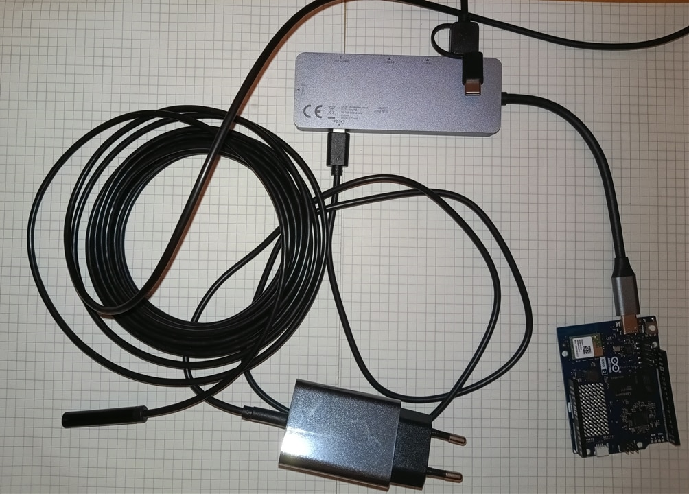
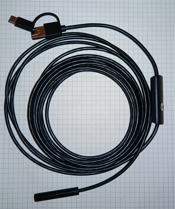
I tested several cameras. Unfortunately, some of them do not work properly with the Arduino Q. Despite my efforts, I could not get the rather old Megapixel USB2 Webcam Live WB-5400 - 15007 (which runs on USB 2.0) to work. The project uses a 3-in-1 Waterproof USB Endoscope Inspection Camera. The integrated ultra-bright LEDs and 1200P HD camera make it able to present images with a color effect while retaining high resolution and quality even in dark places. In addition, the lens is equipped with automatic exposure and blue light technology, which can effectively filter stray light, restore real scenes, and make images clearer.
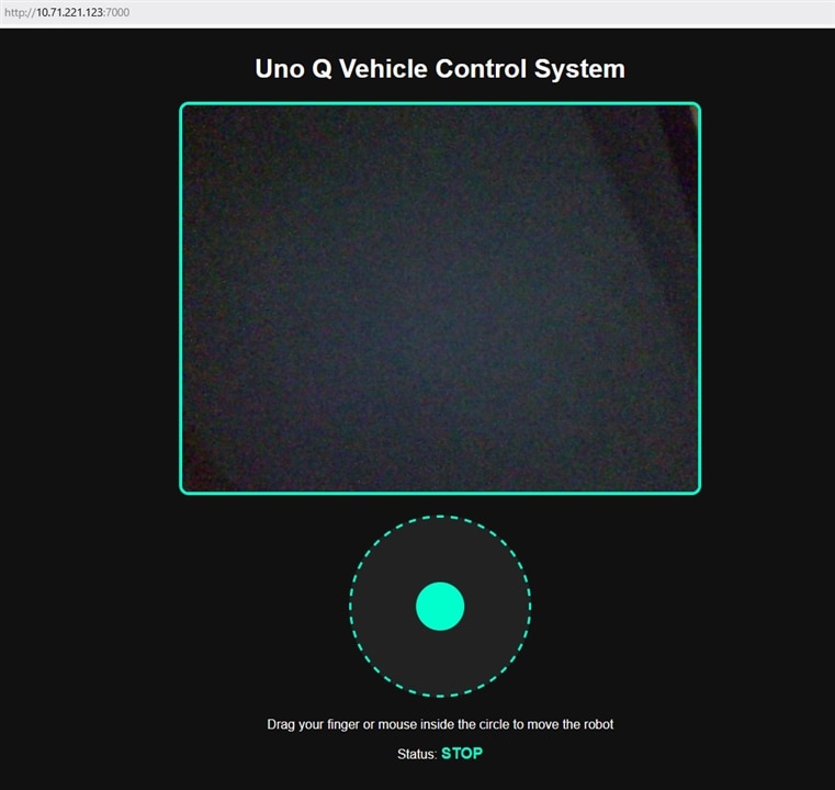
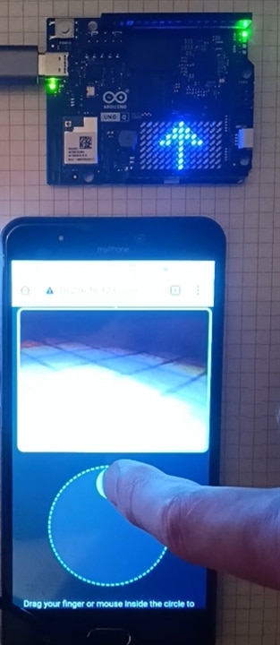
A web page containing a camera feed along with a joystick can be displayed on a computer or a mobile device. This offers tremendous possibilities for the user, allowing them to control the vehicle not only locally from an apartment but also remotely. The view of the page is shown in the image. After refreshing the page in your phone/computer browser: Below the video window, you will see a dark gray circle with a dashed light blue border. When you click or tap inside this circle, a light blue, movable joystick will immediately appear there, allowing you to control the vehicle.
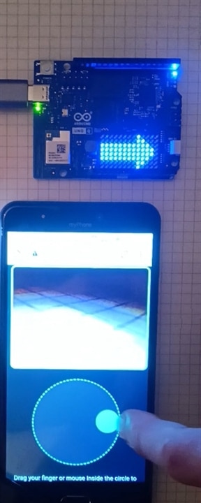
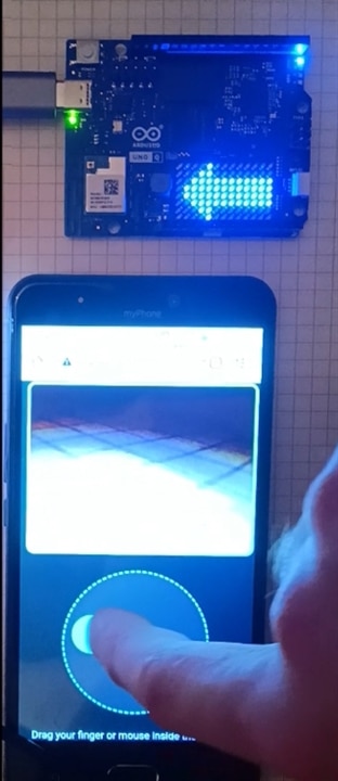
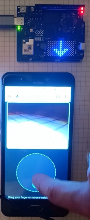
The image below shows the website running on a smartphone. As you can see, there's no need to create and install a dedicated app—a standard web browser will suffice.
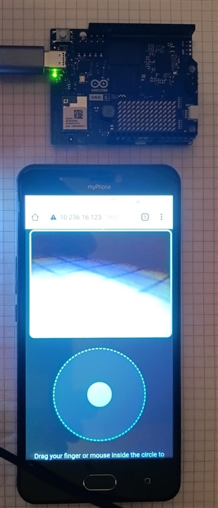
For diagnostic purposes, the built-in LEDs on the Arduino Uno board were used to indicate the vehicle's status: a lit blue LED indicates turning left or right, green indicates moving forward, and red indicates moving backward. Additionally, the matrix display shows arrows indicating the direction in which the vehicle is moving.
You can also watch a video showing how the website works on YouTube:
https://www.youtube.com/watch?v=E3mmpFuwCU4
Firmware Implementation: Motor Control and RPC Communication
1. Libraries and System Architecture
#include <Arduino_RouterBridge.h> // Official RPC header for Uno Q
#include <Arduino_LED_Matrix.h>   // 8x13 Matrix library

Arduino_LED_Matrix matrix; // Initialize the LED matrix

    <Arduino_RouterBridge.h>: The official Remote Procedure Call (RPC) library for the Arduino UNO Q. It establishes a communication bridge between the microcontroller unit (MCU) running C++ and the Linux host system running Python (main.py).

    <Arduino_LED_Matrix.h>: The library used to control the built-in 8×13 LED matrix display.

    Arduino_LED_Matrix matrix;: Instantiates the matrix driver object to draw graphical frames.
2. Pin Mapping and Constants
// Motor pin definitions for Elecrow kit (H-bridges)
const int MOTOR_L_F = 4;
const int MOTOR_L_B = 5;
const int MOTOR_R_F = 6;
const int MOTOR_R_B = 7;

const uint8_t FRAME_SIZE = 8 * 13; // 104 pixels

    Motor Pins:

        MOTOR_L_F (Pin 4) & MOTOR_L_B (Pin 5): Left motor forward and backward channels.

        MOTOR_R_F (Pin 6) & MOTOR_R_B (Pin 7): Right motor forward and backward channels.

    FRAME_SIZE = 8 * 13: Defines the total pixel array size (104 pixels) for the LED matrix.
3. LED Matrix Graphic Data Arrays
// 1. UP ARROW (FORWARD)
uint8_t arrow_up[FRAME_SIZE] = {
    0, 0, 0, 0, 0, 0, 7, 0, 0, 0, 0, 0, 0,
    0, 0, 0, 0, 0, 7, 7, 7, 0, 0, 0, 0, 0,
    0, 0, 0, 0, 7, 7, 7, 7, 7, 0, 0, 0, 0,
    0, 0, 0, 7, 7, 0, 7, 0, 7, 7, 0, 0, 0,
    0, 0, 0, 0, 0, 0, 7, 0, 0, 0, 0, 0, 0,
    0, 0, 0, 0, 0, 0, 7, 0, 0, 0, 0, 0, 0,
    0, 0, 0, 0, 0, 0, 7, 0, 0, 0, 0, 0, 0,
    0, 0, 0, 0, 0, 0, 7, 0, 0, 0, 0, 0, 0
};

// 5. CLEAR DISPLAY (STOP)
uint8_t stop_icon[FRAME_SIZE] = { 0 }; // All pixels off (value 0)
Four 1D byte arrays (arrow_up, arrow_down, arrow_left, arrow_right) and one blank array (stop_icon) represent visual icons.
Grayscale Value Mapping: Each index corresponds to one pixel. Values range from 0 (LED completely off) to 7 (maximum LED brightness).
The visual layout inside the code mimics the 8×13 grid structure to visualize arrow shapes directly in the source file.
4. Helper Functions
set_led4_color(bool r, bool g, bool b)
// Function controlling the built-in LED4 using inverted logic
void set_led4_color(bool r, bool g, bool b) {
  digitalWrite(LED4_R, r ? LOW : HIGH);
  digitalWrite(LED4_G, g ? LOW : HIGH);
  digitalWrite(LED4_B, b ? LOW : HIGH);
}
Controls the onboard RGB LED (LED4).
Active-Low Logic: The pins use inverted logic. Setting a pin to LOW turns the corresponding color component ON, whereas setting it to HIGH turns it OFF (handled via ternary operators r ? LOW : HIGH).
move_robot_mcu(String direction)
// Function receiving commands from the web page (via RPC bridge)
void move_robot_mcu(String direction) {
  if (direction == "F") { // FORWARD
    digitalWrite(MOTOR_L_F, HIGH); digitalWrite(MOTOR_R_F, HIGH);
    digitalWrite(MOTOR_L_B, LOW);  digitalWrite(MOTOR_R_B, LOW);

    set_led4_color(false, true, false); // GREEN
    matrix.draw(arrow_up);               // Display up arrow
  }
  else if (direction == "B") { // BACKWARD
    digitalWrite(MOTOR_L_F, LOW);  digitalWrite(MOTOR_R_F, LOW);
    digitalWrite(MOTOR_L_B, HIGH); digitalWrite(MOTOR_R_B, HIGH);

    set_led4_color(true, false, false); // RED
    matrix.draw(arrow_down);             // Display down arrow
  }
  // ... (additional conditions for "L" and "R")
  else { // STOP ("S")
    digitalWrite(MOTOR_L_F, LOW);  digitalWrite(MOTOR_L_B, LOW);
    digitalWrite(MOTOR_R_F, LOW);  digitalWrite(MOTOR_R_B, LOW);

    set_led4_color(false, false, false); // Turn off RGB LED
    matrix.draw(stop_icon);               // Clear LED matrix
  }
}
The primary execution function triggered via the RPC bridge. It handles drive state, RGB lighting, and matrix rendering simultaneously:
| Input Signal | Action | H-Bridge Motor Pin States | RGB Color | Matrix Graphic |
"F" |
Forward | L_F: HIGH, R_F: HIGH, L_B: LOW, R_B: LOW |
Green | arrow_up |
"B" |
Backward | L_F: LOW, R_F: LOW, L_B: HIGH, R_B: HIGH |
Red | arrow_down |
"L" |
Spin Left | L_F: LOW, R_F: HIGH, L_B: HIGH, R_B: LOW |
Blue | arrow_left |
"R" |
Spin Right | L_F: HIGH, R_F: LOW, L_B: LOW, R_B: HIGH |
Blue | arrow_right |
Else / "S" |
Stop | All motor pins LOW |
Off | stop_icon (Clear) |
5. Program Initialization (setup)
void setup() {
  // Initialize onboard RGB LED4
  pinMode(LED4_R, OUTPUT);
  pinMode(LED4_G, OUTPUT);
  pinMode(LED4_B, OUTPUT);
  set_led4_color(false, false, false);

  // Initialize matrix hardware
  matrix.begin();
  matrix.setGrayscaleBits(3); // Brightness levels from 0 to 7
  matrix.clear();

  // Start the official Linux communication bridge (main.py)
  Bridge.begin();
  Bridge.provide("drive", move_robot_mcu);

  // Initialize motor H-bridge control pins
  pinMode(MOTOR_L_F, OUTPUT); pinMode(MOTOR_L_B, OUTPUT);
  pinMode(MOTOR_R_F, OUTPUT); pinMode(MOTOR_R_B, OUTPUT);

  move_robot_mcu("S"); // Initial state (Vehicle stopped, matrix cleared)
}
RGB LED Setup: Configures LED4_R, LED4_G, and LED4_B as output pins and initializes them to an off state.
Matrix Initialization: Starts the display hardware using matrix.begin(), sets brightness resolution to 3 bits (0-7 scale) via matrix.setGrayscaleBits(3), and clears any leftover pixels.
RPC Bridge Exposure:
Bridge.begin() starts the Linux-MCU communication.
Bridge.provide("drive", move_robot_mcu); registers the move_robot_mcu function under the RPC service name "drive". This allows external Linux scripts or web applications to execute this C++ function remotely over RPC.
Motor Pin Modes: Sets all motor control pins as outputs and enforces an initial STOP state (move_robot_mcu("S")).
6. Main Execution Loop (loop)
void loop() {
  // Empty loop - RPC command handling occurs automatically in the background
  delay(10);
}
The loop() body is intentionally kept empty, containing only a small delay (delay(10)).
Asynchronous Execution: Incoming commands sent from a smartphone, web interface, or Python script are handled in the background by the Arduino_RouterBridge middleware without blocking the main program thread.
Here is the complete project, fully adapted to the native environment of Arduino App Lab, configured for the Elecrow car kit.
#include <Arduino_RouterBridge.h> // Official RPC header for Uno Q
#include <Arduino_LED_Matrix.h>   // 8x13 matrix library

Arduino_LED_Matrix matrix; // Initialize the large matrix

// Motor pin definitions for the Elecrow kit (H-bridges)
const int MOTOR_L_F = 4;
const int MOTOR_L_B = 5;
const int MOTOR_R_F = 6;
const int MOTOR_R_B = 7;

const uint8_t FRAME_SIZE = 8 * 13; // 104 pixels

// 1. UP ARROW (FORWARD)
uint8_t arrow_up[FRAME_SIZE] = {
    0, 0, 0, 0, 0, 0, 7, 0, 0, 0, 0, 0, 0,
    0, 0, 0, 0, 0, 7, 7, 7, 0, 0, 0, 0, 0,
    0, 0, 0, 0, 7, 7, 7, 7, 7, 0, 0, 0, 0,
    0, 0, 0, 7, 7, 0, 7, 0, 7, 7, 0, 0, 0,
    0, 0, 0, 0, 0, 0, 7, 0, 0, 0, 0, 0, 0,
    0, 0, 0, 0, 0, 0, 7, 0, 0, 0, 0, 0, 0,
    0, 0, 0, 0, 0, 0, 7, 0, 0, 0, 0, 0, 0,
    0, 0, 0, 0, 0, 0, 7, 0, 0, 0, 0, 0, 0
};

// 2. DOWN ARROW (BACKWARD)
uint8_t arrow_down[FRAME_SIZE] = {
    0, 0, 0, 0, 0, 0, 7, 0, 0, 0, 0, 0, 0,
    0, 0, 0, 0, 0, 0, 7, 0, 0, 0, 0, 0, 0,
    0, 0, 0, 0, 0, 0, 7, 0, 0, 0, 0, 0, 0,
    0, 0, 0, 0, 0, 0, 7, 0, 0, 0, 0, 0, 0,
    0, 0, 0, 7, 7, 0, 7, 0, 7, 7, 0, 0, 0,
    0, 0, 0, 0, 7, 7, 7, 7, 7, 0, 0, 0, 0,
    0, 0, 0, 0, 0, 7, 7, 7, 0, 0, 0, 0, 0,
    0, 0, 0, 0, 0, 0, 7, 0, 0, 0, 0, 0, 0
};

// 3. LEFT ARROW
uint8_t arrow_left[FRAME_SIZE] = {
    0, 0, 0, 0, 7, 0, 0, 0, 0, 0, 0, 0, 0,
    0, 0, 0, 7, 7, 0, 0, 0, 0, 0, 0, 0, 0,
    0, 0, 7, 7, 7, 7, 7, 7, 7, 7, 7, 7, 7,
    0, 7, 7, 7, 7, 7, 7, 7, 7, 7, 7, 7, 7,
    0, 7, 7, 7, 7, 7, 7, 7, 7, 7, 7, 7, 7,
    0, 0, 7, 7, 7, 7, 7, 7, 7, 7, 7, 7, 7,
    0, 0, 0, 7, 7, 0, 0, 0, 0, 0, 0, 0, 0,
    0, 0, 0, 0, 7, 0, 0, 0, 0, 0, 0, 0, 0
};

// 4. RIGHT ARROW
uint8_t arrow_right[FRAME_SIZE] = {
    0, 0, 0, 0, 0, 0, 0, 0, 7, 0, 0, 0, 0,
    0, 0, 0, 0, 0, 0, 0, 0, 7, 7, 0, 0, 0,
    7, 7, 7, 7, 7, 7, 7, 7, 7, 7, 7, 0, 0,
    7, 7, 7, 7, 7, 7, 7, 7, 7, 7, 7, 7, 0,
    7, 7, 7, 7, 7, 7, 7, 7, 7, 7, 7, 7, 0,
    7, 7, 7, 7, 7, 7, 7, 7, 7, 7, 0, 0,
    0, 0, 0, 0, 0, 0, 0, 0, 7, 7, 0, 0, 0,
    0, 0, 0, 0, 0, 0, 0, 0, 7, 0, 0, 0, 0
};

// 5. CLEAR DISPLAY (STOP)
uint8_t stop_icon[FRAME_SIZE] = { 0 }; // All pixels off (value 0)

// Function controlling the built-in LED4 using inverted logic
void set_led4_color(bool r, bool g, bool b) {
  digitalWrite(LED4_R, r ? LOW : HIGH);
  digitalWrite(LED4_G, g ? LOW : HIGH);
  digitalWrite(LED4_B, b ? LOW : HIGH);
}

// Function receiving commands from the web page (via RPC bridge)
void move_robot_mcu(String direction) {
  if (direction == "F") { // FORWARD
    digitalWrite(MOTOR_L_F, HIGH); digitalWrite(MOTOR_R_F, HIGH);
    digitalWrite(MOTOR_L_B, LOW);  digitalWrite(MOTOR_R_B, LOW);

    set_led4_color(false, true, false); // GREEN
    matrix.draw(arrow_up);               // Display up arrow
  }
  else if (direction == "B") { // BACKWARD
    digitalWrite(MOTOR_L_F, LOW);  digitalWrite(MOTOR_R_F, LOW);
    digitalWrite(MOTOR_L_B, HIGH); digitalWrite(MOTOR_R_B, HIGH);

    set_led4_color(true, false, false); // RED
    matrix.draw(arrow_down);             // Display down arrow
  }
  else if (direction == "L") { // LEFT
    digitalWrite(MOTOR_L_F, LOW);  digitalWrite(MOTOR_R_F, HIGH);
    digitalWrite(MOTOR_L_B, HIGH); digitalWrite(MOTOR_R_B, LOW);

    set_led4_color(false, false, true); // BLUE
    matrix.draw(arrow_left);             // Display left arrow
  }
  else if (direction == "R") { // RIGHT
    digitalWrite(MOTOR_L_F, HIGH); digitalWrite(MOTOR_R_F, LOW);
    digitalWrite(MOTOR_L_B, LOW);  digitalWrite(MOTOR_R_B, HIGH);

    set_led4_color(false, false, true); // BLUE
    matrix.draw(arrow_right);            // Display right arrow
  }
  else { // STOP ("S")
    digitalWrite(MOTOR_L_F, LOW);  digitalWrite(MOTOR_L_B, LOW);
    digitalWrite(MOTOR_R_F, LOW);  digitalWrite(MOTOR_R_B, LOW);

    set_led4_color(false, false, false); // Turn off RGB LED
    matrix.draw(stop_icon);               // Clear LED matrix
  }
}

void setup() {
  // Initialize built-in LED4
  pinMode(LED4_R, OUTPUT);
  pinMode(LED4_G, OUTPUT);
  pinMode(LED4_B, OUTPUT);
  set_led4_color(false, false, false);

  // Initialize the matrix exactly as in the working example
  matrix.begin();
  matrix.setGrayscaleBits(3); // Brightness levels from 0 to 7
  matrix.clear();

  // Start the official communication bridge with Linux (main.py)
  Bridge.begin();
  Bridge.provide("drive", move_robot_mcu);

  // Initialize control pins for motor H-bridges
  pinMode(MOTOR_L_F, OUTPUT); pinMode(MOTOR_L_B, OUTPUT);
  pinMode(MOTOR_R_F, OUTPUT); pinMode(MOTOR_R_B, OUTPUT);

  move_robot_mcu("S"); // Initial state (Vehicle stopped, matrix off)
}

void loop() {
  // Empty loop - handling RPC commands from the phone happens automatically in the background
  delay(10);
}
#include <Arduino.h>
#include <Arduino_RouterBridge.h> // Official RPC header for Uno Q
#include <Arduino_LED_Matrix.h>   // Library for the 8x13 LED matrix

Arduino_LED_Matrix matrix; // Initialize the large LED matrix

// --- HARDWARE PIN CONFIGURATION ---
const int motorPinA_1A = 5;
const int motorPinA_1B = 6;
const int motorPinB_1A = 9;
const int motorPinB_1B = 10;

const int IR_RECEIVE_PIN = 2;
const int trigPin = 4;
const int echoPin = 3;

// Physical Tactile Bumpers
const int CollisionPin_L = 18; // Pin A4
const int CollisionPin_R = 19; // Pin A5

// Line Tracking Photo-interrupters
const int TrackingPin_L = A2;
const int TrackingPin_R = A3;

// --- ROBOT PARAMETERS AND MODES ---
enum RobotMode { MODE_MANUAL, MODE_AUTONOMOUS };
RobotMode currentMode = MODE_MANUAL;

const int motorSpeed = 200;
int spd = 195; // Specific heavy escape/evasive speed vector
int trackSpeed = 160; // Optimized track following velocity for Uno Q

unsigned long lastCommandTime = 0;
const unsigned long commandTimeout = 250;
const uint8_t FRAME_SIZE = 8 * 13; // 104 pixels for the LED matrix
byte lastCommand = 0;

// --- LED MATRIX ARROW ARRAYS (Brightness levels 0-7) ---
uint8_t arrow_up[FRAME_SIZE] = {
 0, 0, 0, 0, 0, 0, 7, 0, 0, 0, 0, 0, 0,
 0, 0, 0, 0, 0, 7, 7, 7, 0, 0, 0, 0, 0,
 0, 0, 0, 0, 7, 7, 7, 7, 7, 0, 0, 0, 0,
 0, 0, 0, 7, 7, 0, 7, 0, 7, 7, 0, 0, 0,
 0, 0, 0, 0, 0, 0, 7, 0, 0, 0, 0, 0, 0,
 0, 0, 0, 0, 0, 0, 7, 0, 0, 0, 0, 0, 0,
 0, 0, 0, 0, 0, 0, 7, 0, 0, 0, 0, 0, 0,
 0, 0, 0, 0, 0, 0, 7, 0, 0, 0, 0, 0, 0
};
uint8_t arrow_down[FRAME_SIZE] = {
 0, 0, 0, 0, 0, 0, 7, 0, 0, 0, 0, 0, 0,
 0, 0, 0, 0, 0, 0, 7, 0, 0, 0, 0, 0, 0,
 0, 0, 0, 0, 0, 0, 7, 0, 0, 0, 0, 0, 0,
 0, 0, 0, 0, 0, 0, 7, 0, 0, 0, 0, 0, 0,
 0, 0, 0, 7, 7, 0, 7, 0, 7, 7, 0, 0, 0,
 0, 0, 0, 0, 7, 7, 7, 7, 7, 0, 0, 0, 0,
 0, 0, 0, 0, 0, 7, 7, 7, 0, 0, 0, 0, 0,
 0, 0, 0, 0, 0, 0, 7, 0, 0, 0, 0, 0, 0
};
uint8_t arrow_left[FRAME_SIZE] = {
 0, 0, 0, 0, 7, 0, 0, 0, 0, 0, 0, 0, 0,
 0, 0, 0, 7, 7, 0, 0, 0, 0, 0, 0, 0, 0,
 0, 0, 7, 7, 7, 7, 7, 7, 7, 7, 7, 7, 7,
 0, 7, 7, 7, 7, 7, 7, 7, 7, 7, 7, 7, 7,
 0, 7, 7, 7, 7, 7, 7, 7, 7, 7, 7, 7, 7,
 0, 0, 7, 7, 7, 7, 7, 7, 7, 7, 7, 7, 7,
 0, 0, 0, 7, 7, 0, 0, 0, 0, 0, 0, 0, 0,
 0, 0, 0, 0, 7, 0, 0, 0, 0, 0, 0, 0, 0
};
uint8_t arrow_right[FRAME_SIZE] = {
 0, 0, 0, 0, 0, 0, 0, 0, 7, 0, 0, 0, 0,
 0, 0, 0, 0, 0, 0, 0, 0, 7, 7, 0, 0, 0,
 7, 7, 7, 7, 7, 7, 7, 7, 7, 7, 7, 0, 0,
 7, 7, 7, 7, 7, 7, 7, 7, 7, 7, 7, 7, 0,
 7, 7, 7, 7, 7, 7, 7, 7, 7, 7, 7, 7, 0,
 7, 7, 7, 7, 7, 7, 7, 7, 7, 7, 7, 0, 0,
 0, 0, 0, 0, 0, 0, 0, 0, 7, 7, 0, 0, 0,
 0, 0, 0, 0, 0, 0, 0, 0, 7, 0, 0, 0, 0
};
uint8_t stop_icon[FRAME_SIZE] = { 0 };

// --- ONBOARD RGB LED CONTROL FUNCTIONS ---
void set_led3_color(int r, int g, int b) {
 analogWrite(LED3_R, r);
 analogWrite(LED3_G, g);
 analogWrite(LED3_B, b);
}
void set_led4_color(bool r, bool g, bool b) {
 digitalWrite(LED4_R, r ? LOW : HIGH);
 digitalWrite(LED4_G, g ? LOW : HIGH);
 digitalWrite(LED4_B, b ? LOW : HIGH);
}

// --- MOTOR DRIVE DRIVER ---
void motor(int A1, int A2, int B1, int B2) {
 analogWrite(motorPinA_1A, A1);
 analogWrite(motorPinA_1B, A2);
 analogWrite(motorPinB_1A, B1);
 analogWrite(motorPinB_1B, B2);
}

// --- NATIVE IR DECODER FOR ARDUINO UNO Q ---
long readElecrowIR() {
  int count = 0;
  while (digitalRead(IR_RECEIVE_PIN) == LOW && count < 200) {
    count++;
    delayMicroseconds(60);
  }
  if (count >= 200) return -1;

  count = 0;
  while (digitalRead(IR_RECEIVE_PIN) == HIGH && count < 80) {
    count++;
    delayMicroseconds(60);
  }
  if (count >= 80) return -1;

  int idx = 0;
  int cnt = 0;
  byte data[4] = {0, 0, 0, 0};

  for (int i = 0; i < 32; i++) {
    count = 0;
    while (digitalRead(IR_RECEIVE_PIN) == LOW && count < 15) {
      count++;
      delayMicroseconds(60);
    }
    count = 0;
    while (digitalRead(IR_RECEIVE_PIN) == HIGH && count < 40) {
      count++;
      delayMicroseconds(60);
    }
    if (count > 8) {
      data[idx] |= (1 << cnt);
    }
    if (cnt == 7) {
      cnt = 0;
      idx++;
    } else {
      cnt++;
    }
  }

  if ((byte)(data[0] + data[1]) == 0xFF && (byte)(data[2] + data[3]) == 0xFF) {
    return data[2];
  }
  return -1;
}

// --- WEB INTERFACE INTERCEPTOR (FIXED: Changed argument type to String) ---
void move_robot_mcu(String direction) {
 if (currentMode != MODE_MANUAL) return;

 if (direction == "F") {
 motor(0, motorSpeed, 0, motorSpeed);
 set_led4_color(false, true, false);
 set_led3_color(0, 200, 0);
 matrix.draw(arrow_up);
 }
 else if (direction == "B") {
 motor(motorSpeed, 0, motorSpeed, 0);
 set_led4_color(true, false, false);
 set_led3_color(200, 0, 0);
 matrix.draw(arrow_down);
 }
 else if (direction == "L") {
 motor(motorSpeed, 0, 0, motorSpeed);
 set_led4_color(false, false, true);
 set_led3_color(0, 0, 200);
 matrix.draw(arrow_left);
 }
 else if (direction == "R") {
 motor(0, motorSpeed, motorSpeed, 0);
 set_led4_color(false, false, true);
 set_led3_color(0, 0, 200);
 matrix.draw(arrow_right);
 }
 else {
 motor(0, 0, 0, 0);
 set_led4_color(false, false, false);
 set_led3_color(0, 0, 0);
 matrix.draw(stop_icon);
 }
}

float getDistance() {
 digitalWrite(trigPin, LOW);
 delayMicroseconds(2);
 digitalWrite(trigPin, HIGH);
 delayMicroseconds(10);
 digitalWrite(trigPin, LOW);

 long duration = pulseIn(echoPin, HIGH, 30000);
 float d = duration * 0.0343 / 2;
 if (d == 0) return 999.0;
 return d;
}

// --- WEB MODE TOGGLE (FIXED: Changed argument type to String) ---
void toggle_mode_from_web(String cmd) {
 if (currentMode == MODE_MANUAL) {
 currentMode = MODE_AUTONOMOUS;
 set_led3_color(200, 200, 0);
 Serial.println("System Notification: AUTONOMY MODE ENGAGED VIA WEB.");
 } else {
 currentMode = MODE_MANUAL;
 motor(0, 0, 0, 0);
 set_led3_color(0, 0, 0);
 matrix.draw(stop_icon);
 Serial.println("System Notification: MANUAL OVERRIDE ENGAGED VIA WEB.");
 }
}

void exec_cmd(byte key_val) {
 switch (key_val) {
 case 0x1C:
 if (currentMode == MODE_MANUAL) {
 currentMode = MODE_AUTONOMOUS;
 set_led3_color(200, 200, 0);
 Serial.println("System Notification: AUTONOMY MODE ENGAGED.");
 } else {
 currentMode = MODE_MANUAL;
 motor(0, 0, 0, 0);
 set_led3_color(0, 0, 0);
 matrix.draw(stop_icon);
 Serial.println("System Notification: MANUAL OVERRIDE ENGAGED.");
 }
 lastCommand = 0;
 delay(500);
 break;
 case 0x18: if (currentMode == MODE_MANUAL) { motor(0, motorSpeed, 0, motorSpeed); matrix.draw(arrow_up); } break;
 case 0x08: if (currentMode == MODE_MANUAL) { motor(motorSpeed, 0, 0, motorSpeed); matrix.draw(arrow_left); } break;
 case 0x5A: if (currentMode == MODE_MANUAL) { motor(0, motorSpeed, motorSpeed, 0); matrix.draw(arrow_right); } break;
 case 0x52: if (currentMode == MODE_MANUAL) { motor(motorSpeed, 0, motorSpeed, 0); matrix.draw(arrow_down); } break;
 default: if (currentMode == MODE_MANUAL) { motor(0, 0, 0, 0); matrix.draw(stop_icon); } break;
 }
}

void setup() {
 Serial.begin(115200);

 pinMode(IR_RECEIVE_PIN, INPUT_PULLUP);
 pinMode(trigPin, OUTPUT);
 pinMode(echoPin, INPUT);
 pinMode(CollisionPin_L, INPUT);
 pinMode(CollisionPin_R, INPUT);
 pinMode(TrackingPin_L, INPUT_PULLUP);
 pinMode(TrackingPin_R, INPUT_PULLUP);

 pinMode(LED4_R, OUTPUT); pinMode(LED4_G, OUTPUT); pinMode(LED4_B, OUTPUT);
 set_led3_color(0, 0, 0);
 set_led4_color(false, false, false);
 matrix.begin();
 matrix.setGrayscaleBits(3);
 matrix.clear();

 // --- RPC BRIDGE REGISTRATION ---
 Bridge.begin();
 Bridge.provide("drive", move_robot_mcu);
 Bridge.provide("toggle_mode", toggle_mode_from_web);

 Serial.println("System Core Ready.");
}

void loop() {
  // 1. IR Remote control handling
  if (digitalRead(IR_RECEIVE_PIN) == LOW) {
    long result = readElecrowIR();
    if (result != -1) {
      lastCommand = (byte)result;
      exec_cmd(lastCommand);
      if (currentMode == MODE_MANUAL) lastCommandTime = millis();
    }
  }

  // 2. Motion modes execution logic
  if (currentMode == MODE_MANUAL) {
    if (digitalRead(IR_RECEIVE_PIN) == HIGH) {
      if (millis() - lastCommandTime > commandTimeout) {
        motor(0, 0, 0, 0);
      }
    } else {
      exec_cmd(lastCommand);
    }
  }
  else if (currentMode == MODE_AUTONOMOUS) {
    float distance = getDistance();
    int sumVal = (digitalRead(CollisionPin_L) == HIGH ? 1 : 0) * 2 + (digitalRead(CollisionPin_R) == HIGH ? 1 : 0);

    // --- HIERARCHY 1: Physical Bumpers ---
    if (sumVal > 0) {
      Serial.print("TACTILE COLLISION TRIGGERED. Code: ");
      Serial.println(sumVal);
      matrix.draw(stop_icon);

      if (sumVal == 1) {
        motor(spd, 0, spd, 0); delay(2000);
        motor(spd, 0, 0, spd); delay(2000);
      }
      else if (sumVal == 2) {
        motor(spd, 0, spd, 0); delay(2000);
        motor(0, spd, spd, 0); delay(2000);
      }
      else if (sumVal == 3) {
        motor(spd, 0, spd, 0); delay(2000);
        motor(spd, 0, 0, spd); delay(2000);
      }
    }
    // --- HIERARCHY 2: Ultrasonic Sensor (Sonar) ---
    else if (distance < 30) {
      matrix.draw(arrow_left);
      motor(motorSpeed, 0, 0, motorSpeed);
      delay(300);
    }
    // --- HIERARCHY 3: Line Tracking ---
    else {
      int trackL = digitalRead(TrackingPin_L);
      int trackR = digitalRead(TrackingPin_R);
      int Track = trackL * 2 + trackR;

      switch (Track) {
        case 0:
          motor(0, 0, 0, 0);
          matrix.draw(stop_icon);
          break;
        case 1:
          motor(0, trackSpeed, trackSpeed, 0);
          matrix.draw(arrow_right);
          break;
        case 2:
          motor(trackSpeed, 0, 0, trackSpeed);
          matrix.draw(arrow_left);
          break;
        case 3:
          motor(0, trackSpeed, 0, trackSpeed);
          matrix.draw(arrow_up);
          break;
      }
      delay(10);
    }
  }
  Bridge.update();
}
2. Python Web Server (main.py)
from arduino.app_utils import *
from arduino.app_bricks.web_ui import WebUI
from arduino.app_peripherals.camera import Camera

# Initialize the onboard USB camera module
camera = Camera(resolution=(640, 480), fps=15)
ui = WebUI()
camera.start()

# API endpoint executed when a drag action occurs on the webpage
def handle_joystick(data: dict):
    char_cmd = data.get('cmd', 'S')
    # Forward command directly to the registered C++ function
    Bridge.call("drive", char_cmd)
    return {"status": "ok"}

# Expose API and camera routes to App Lab web interface
ui.expose_api("POST", "/api/move", handle_joystick)
ui.expose_camera("/camera", camera)

App.run()
3. Local Dashboard UI (assets/index.html)
<!doctype html>
<html lang="en">
  <head>
    <meta charset="UTF-8" />
    <meta name="viewport" content="width=device-width, initial-scale=1.0" />
    <title>Uno Q Robot Dashboard</title>
    <style>
      body { font-family: Arial, sans-serif; text-align: center; background: #111; color: #fff; margin: 0; padding: 10px; }
      #control-pad { width: 220px; height: 220px; background: #222; border-radius: 50%; margin: 25px auto; position: relative; border: 3px dashed #00ffcc; touch-action: none; }
      img { border: 4px solid #00ffcc; border-radius: 12px; max-width: 100%; height: auto; display: block; margin: 0 auto; }
      .status { font-weight: bold; color: #00ffcc; font-size: 1.2em; }
    </style>
  </head>
  <body>
    <h1>Uno Q Vehicle Control System</h1>
    <div>
      <img src="/camera" />
    </div>

    <div id="control-pad"></div>
    <p>Drag your finger or mouse inside the circle to move the robot</p>
    <p>Status: <span id="status-val" class="status">STOP</span></p>

    <script>
      const pad = document.getElementById('control-pad');
      const statusText = document.getElementById('status-val');
      let isMoving = false;
      let lastDirection = "S";
      let lastSend = 0;

      // Create a visual handle inside the control pad area
      const knob = document.createElement('div');
      knob.style.width = '60px'; knob.style.height = '60px'; knob.style.background = '#00ffcc';
      knob.style.borderRadius = '50%'; knob.style.position = 'absolute';
      knob.style.left = '80px'; knob.style.top = '80px'; knob.style.pointerEvents = 'none';
      pad.appendChild(knob);

      function startAction() { isMoving = true; }

      function moveAction(e) {
        if (!isMoving) return;
        e.preventDefault();

        const rect = pad.getBoundingClientRect();
        const input = e.touches ? e.touches[0] : e;

        const centerX = rect.width / 2;
        const centerY = rect.height / 2;

        let x = input.clientX - rect.left - centerX;
        let y = input.clientY - rect.top - centerY;

        const distance = Math.sqrt(x*x + y*y);
        if (distance > 80) {
          x = (x / distance) * 80;
          y = (y / distance) * 80;
        }

        knob.style.transform = `translate(${x}px, ${y}px)`;

        if (Date.now() - lastSend < 70) return;

        let cmd = "S";
        if (Math.abs(x) > Math.abs(y)) {
          cmd = x > 25 ? "R" : (x < -25 ? "L" : "S");
        } else {
          cmd = y > 25 ? "B" : (y < -25 ? "F" : "S");
        }

        if (cmd !== lastDirection) {
          lastDirection = cmd;
          lastSend = Date.now();

          const names = {"F": "FORWARD ▲", "B": "BACKWARD ▼", "L": "LEFT Arrow backward", "R": "RIGHT Arrow forward", "S": "STOP"};
          statusText.innerText = names[cmd];

          sendCmd(cmd);
        }
      }

      function endAction() {
        isMoving = false;
        knob.style.transform = 'translate(0px, 0px)';
        if (lastDirection !== "S") {
          lastDirection = "S";
          statusText.innerText = "STOP";
          sendCmd("S");
        }
      }

      pad.addEventListener('mousedown', startAction);
      window.addEventListener('mousemove', moveAction);
      window.addEventListener('mouseup', endAction);

      pad.addEventListener('touchstart', startAction);
      window.addEventListener('touchmove', moveAction, { passive: false });
      window.addEventListener('touchend', endAction);

      function sendCmd(character) {
        fetch('/api/move', {
          method: 'POST',
          headers: { 'Content-Type': 'application/json' },
          body: JSON.stringify({ cmd: character })
        }).catch(err => console.log(err));
      }
    </script>
  </body>
</html>