


Project Roadmap
Part 1 - Experimental Smart Assistive Platform for Elderly and Disabled People
Part 3 - Wireless Command and H-Bridge Direct Drive
Part 4 - Introducing Autonomous Line Following (TCRT5000)
Part 5 - Non-Contact Proactive Shielding (HC-SR04 Range Finder)
Part 6 - Strict Priority Hierarchy with Tactile Mechanical Bumpers
Part 7 - Mobile Robot Control and Live Video Streaming

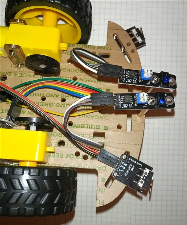
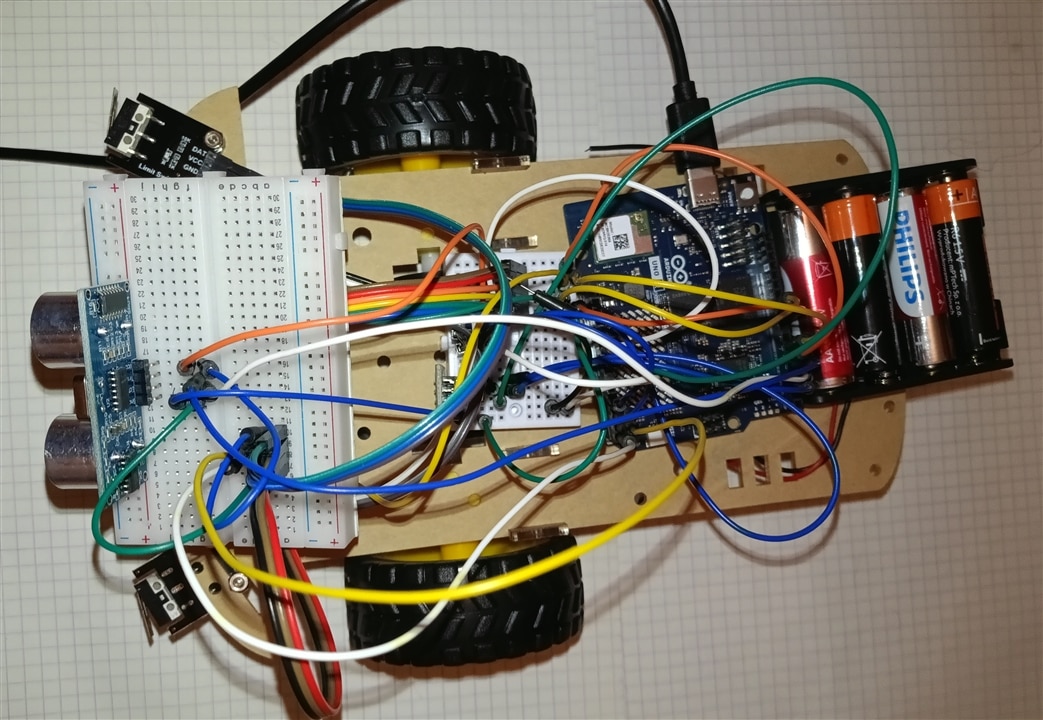
The primary addition is the support for physical collision sensors (bumpers) along with a 3-level safety hierarchy for handling obstacles.
1. Pin Definitions and Escape Speed
Explanation:// Physical Tactile Bumpers (Mapped to pins A4 and A5 on Arduino) const int COLLISION_PIN_L = 18; // Pin A4 const int COLLISION_PIN_R = 19; // Pin A5 const int ESCAPE_SPEED = 195; // Specific heavy escape/evasive speed vector
Added two new pins corresponding to the left (A4 / digital pin 18) and right (A5 / digital pin 19) physical collision microswitches/bumpers.
Defined ESCAPE_SPEED = 195, a dedicated motor speed used during longer backing-up and evasive maneuvers triggered by physical impacts.
2. Sensor Initialization in setup()
// Set as INPUT to match the original sponatenous logic of Elecrow modules
pinMode(COLLISION_PIN_L, INPUT);
pinMode(COLLISION_PIN_R, INPUT);
Explanation: Sets the bumper pins as standard digital inputs (INPUT). These modules send a high signal (HIGH / 1) to the pin when pressed.
3. Safety Hierarchy Logic in loop()
In autonomous mode (MODE_AUTONOMOUS), the code now executes operations based on a 3-level priority hierarchy:
Step 1: Read Bumper States (Binary Code)
int collisionState = (digitalRead(COLLISION_PIN_L) == HIGH ? 1 : 0) * 2 + (digitalRead(COLLISION_PIN_R) == HIGH ? 1 : 0);
Creates a bitwise variable collisionState with the following possible values:
-
0– No collision. -
1– Right-side collision. -
2– Left-side collision. -
3– Central collision (both bumpers pressed).
Priority 1: Physical Impact Response (Bumpers)
This is the top priority, handling cases where the robot has physically made contact with an obstacle (e.g., an object below the ultrasonic beam):
if (collisionState > 0) {
  Serial.print("TACTILE COLLISION TRIGGERED. Code: ");
  Serial.println(collisionState);

  switch (collisionState) {
    case 1: // Right collision -> Reverse for 2s, then turn left for 2s
      driveMotors(ESCAPE_SPEED, 0, ESCAPE_SPEED, 0); delay(2000);
      driveMotors(ESCAPE_SPEED, 0, 0, ESCAPE_SPEED); delay(2000);
      break;
    case 2: // Left collision -> Reverse for 2s, then turn right for 2s
      driveMotors(ESCAPE_SPEED, 0, ESCAPE_SPEED, 0); delay(2000);
      driveMotors(0, ESCAPE_SPEED, ESCAPE_SPEED, 0); delay(2000);
      break;
    case 3: // Central collision -> Reverse for 2s, then perform U-turn (left) for 2s
      driveMotors(ESCAPE_SPEED, 0, ESCAPE_SPEED, 0); delay(2000);
      driveMotors(ESCAPE_SPEED, 0, 0, ESCAPE_SPEED); delay(2000);
      break;
  }
}
Behavior: Upon impact, the robot reverses for 2 seconds, then spins away from the side of impact for 2 seconds to clear the obstacle.
Priority 2: Proactive Distance Check (HC-SR04 Sonar)
If no physical collision occurred (collisionState == 0), the code checks the ultrasonic rangefinder:
else if (distance < 30.0) {
  Serial.println("Obstacle detected by Sonar! Turning left...");
  driveMotors(MOTOR_SPEED, 0, 0, MOTOR_SPEED);
  delay(300);
}
Behavior: If an obstacle is detected within 30 cm, the robot performs a short left turn 30ms to steer around the obstacle before physical contact happens.
Priority 3: Line Following Routine
If there is no physical impact and no obstacles within 30cm, the robot falls back to standard line tracking logic (else { ... }).
Here is the complete, merged C program for the Arduino UNO Q, incorporating all features from all previous versions:
-
IR Remote Control
-
Line Tracking
-
HC-SR04 Ultrasonic Distance Sensor
-
Physical Tactile Collision Bumpers
-
Onboard RGB LED indicators (
LED3andLED4) -
8x13 LED Matrix Display (displaying directional arrows and the STOP icon)
#include <Arduino.h>
#include <Arduino_LED_Matrix.h> // Library for the 8x13 LED matrix

Arduino_LED_Matrix matrix; // Initialize LED matrix object

// L9110S Motor Driver Pins
const int MOTOR_PIN_A1 = 5;
const int MOTOR_PIN_A2 = 6;
const int MOTOR_PIN_B1 = 9;
const int MOTOR_PIN_B2 = 10;

// Infrared Receiver Pin
const int IR_RECEIVE_PIN = 2;

// Line Tracking Sensor Pins
const int TRACKING_PIN_L = A2;
const int TRACKING_PIN_R = A3;

// Ultrasonic HC-SR04 Sonar Pins
const int TRIG_PIN = 4;
const int ECHO_PIN = 3;

// Physical Tactile Bumpers
const int COLLISION_PIN_L = 18; // Pin A4
const int COLLISION_PIN_R = 19; // Pin A5

enum RobotMode {
  MODE_MANUAL,
  MODE_AUTONOMOUS
};

RobotMode currentMode = MODE_MANUAL;

// Speed settings
const int MOTOR_SPEED = 200;
const int ESCAPE_SPEED = 195; // Speed vector for escape maneuvers after collision
const int TRACK_SPEED = 160;

byte lastCommand = 0;

// LED Matrix Frame Buffer Size (104 pixels)
const uint8_t FRAME_SIZE = 8 * 13;

// --- LED MATRIX ARROW & ICON ARRAYS (Brightness levels 0-7) ---
uint8_t arrow_up[FRAME_SIZE] = {
    0, 0, 0, 0, 0, 0, 7, 0, 0, 0, 0, 0, 0,
    0, 0, 0, 0, 0, 7, 7, 7, 0, 0, 0, 0, 0,
    0, 0, 0, 0, 7, 7, 7, 7, 7, 0, 0, 0, 0,
    0, 0, 0, 7, 7, 0, 7, 0, 7, 7, 0, 0, 0,
    0, 0, 0, 0, 0, 0, 7, 0, 0, 0, 0, 0, 0,
    0, 0, 0, 0, 0, 0, 7, 0, 0, 0, 0, 0, 0,
    0, 0, 0, 0, 0, 0, 7, 0, 0, 0, 0, 0, 0,
    0, 0, 0, 0, 0, 0, 7, 0, 0, 0, 0, 0, 0
};

uint8_t arrow_down[FRAME_SIZE] = {
    0, 0, 0, 0, 0, 0, 7, 0, 0, 0, 0, 0, 0,
    0, 0, 0, 0, 0, 0, 7, 0, 0, 0, 0, 0, 0,
    0, 0, 0, 0, 0, 0, 7, 0, 0, 0, 0, 0, 0,
    0, 0, 0, 0, 0, 0, 7, 0, 0, 0, 0, 0, 0,
    0, 0, 0, 7, 7, 0, 7, 0, 7, 7, 0, 0, 0,
    0, 0, 0, 0, 7, 7, 7, 7, 7, 0, 0, 0, 0,
    0, 0, 0, 0, 0, 7, 7, 7, 0, 0, 0, 0, 0,
    0, 0, 0, 0, 0, 0, 7, 0, 0, 0, 0, 0, 0
};

uint8_t arrow_left[FRAME_SIZE] = {
    0, 0, 0, 0, 7, 0, 0, 0, 0, 0, 0, 0, 0,
    0, 0, 0, 7, 7, 0, 0, 0, 0, 0, 0, 0, 0,
    0, 0, 7, 7, 7, 7, 7, 7, 7, 7, 7, 7, 7,
    0, 7, 7, 7, 7, 7, 7, 7, 7, 7, 7, 7, 7,
    0, 7, 7, 7, 7, 7, 7, 7, 7, 7, 7, 7, 7,
    0, 0, 7, 7, 7, 7, 7, 7, 7, 7, 7, 7, 7,
    0, 0, 0, 7, 7, 0, 0, 0, 0, 0, 0, 0, 0,
    0, 0, 0, 0, 7, 0, 0, 0, 0, 0, 0, 0, 0
};

uint8_t arrow_right[FRAME_SIZE] = {
    0, 0, 0, 0, 0, 0, 0, 0, 7, 0, 0, 0, 0,
    0, 0, 0, 0, 0, 0, 0, 0, 7, 7, 0, 0, 0,
    7, 7, 7, 7, 7, 7, 7, 7, 7, 7, 7, 0, 0,
    7, 7, 7, 7, 7, 7, 7, 7, 7, 7, 7, 7, 0,
    7, 7, 7, 7, 7, 7, 7, 7, 7, 7, 7, 7, 0,
    7, 7, 7, 7, 7, 7, 7, 7, 7, 7, 7, 0, 0,
    0, 0, 0, 0, 0, 0, 0, 0, 7, 7, 0, 0, 0,
    0, 0, 0, 0, 0, 0, 0, 0, 7, 0, 0, 0, 0
};

uint8_t stop_icon[FRAME_SIZE] = { 0 };

// --- ONBOARD RGB LED FUNCTIONS ---
void set_led3_color(int r, int g, int b) {
  analogWrite(LED3_R, r);
  analogWrite(LED3_G, g);
  analogWrite(LED3_B, b);
}

void set_led4_color(bool r, bool g, bool b) {
  digitalWrite(LED4_R, r ? LOW : HIGH);
  digitalWrite(LED4_G, g ? LOW : HIGH);
  digitalWrite(LED4_B, b ? LOW : HIGH);
}

// Elecrow IR Decoder
long readElecrowIR() {
  int count = 0;
  while (digitalRead(IR_RECEIVE_PIN) == LOW && count < 200) { count++; delayMicroseconds(60); }
  if (count >= 200) return -1;

  count = 0;
  while (digitalRead(IR_RECEIVE_PIN) == HIGH && count < 80) { count++; delayMicroseconds(60); }
  if (count >= 80) return -1;

  int idx = 0, cnt = 0;
  byte data[4] = {0, 0, 0, 0};

  for (int i = 0; i < 32; i++) {
    count = 0;
    while (digitalRead(IR_RECEIVE_PIN) == LOW && count < 15) { count++; delayMicroseconds(60); }
    count = 0;
    while (digitalRead(IR_RECEIVE_PIN) == HIGH && count < 40) { count++; delayMicroseconds(60); }

    if (count > 8) data[idx] |= (1 << cnt);

    if (cnt == 7) { cnt = 0; idx++; } else { cnt++; }
  }

  if ((byte)(data[0] + data[1]) == 0xFF && (byte)(data[2] + data[3]) == 0xFF) {
    return data[2];
  }
  return -1;
}

void driveMotors(int a1, int a2, int b1, int b2) {
  analogWrite(MOTOR_PIN_A1, a1);
  analogWrite(MOTOR_PIN_A2, a2);
  analogWrite(MOTOR_PIN_B1, b1);
  analogWrite(MOTOR_PIN_B2, b2);
}

float getDistance() {
  digitalWrite(TRIG_PIN, LOW);
  delayMicroseconds(2);
  digitalWrite(TRIG_PIN, HIGH);
  delayMicroseconds(10);
  digitalWrite(TRIG_PIN, LOW);

  long duration = pulseIn(ECHO_PIN, HIGH, 30000);
  float d = duration * 0.0343 / 2;

  if (d == 0) return 999.0;
  return d;
}

void executeCommand(byte command) {
  switch (command) {
    case 0x1C: // OK Button - Toggle Manual/Autonomous operations
      if (currentMode == MODE_MANUAL) {
        currentMode = MODE_AUTONOMOUS;
        digitalWrite(LED_BUILTIN, HIGH);
        Serial.println("System Notification: AUTONOMY MODE ENGAGED.");
      }
      else {
        currentMode = MODE_MANUAL;
        digitalWrite(LED_BUILTIN, LOW);
        driveMotors(0, 0, 0, 0);
        set_led4_color(false, false, false);
        set_led3_color(0, 0, 0);
        matrix.draw(stop_icon);
        Serial.println("System Notification: MANUAL OVERRIDE ENGAGED.");
      }
      lastCommand = 0;
      delay(500);
      break;

    case 0x18: // Forward
      if (currentMode == MODE_MANUAL) {
        driveMotors(0, MOTOR_SPEED, 0, MOTOR_SPEED);
        set_led4_color(false, true, false); // Green
        set_led3_color(0, 200, 0);
        matrix.draw(arrow_up);
      }
      break;

    case 0x08: // Spin Left
      if (currentMode == MODE_MANUAL) {
        driveMotors(MOTOR_SPEED, 0, 0, MOTOR_SPEED);
        set_led4_color(false, false, true); // Blue
        set_led3_color(0, 0, 200);
        matrix.draw(arrow_left);
      }
      break;

    case 0x5A: // Spin Right
      if (currentMode == MODE_MANUAL) {
        driveMotors(0, MOTOR_SPEED, MOTOR_SPEED, 0);
        set_led4_color(false, false, true); // Blue
        set_led3_color(0, 0, 200);
        matrix.draw(arrow_right);
      }
      break;

    case 0x52: // Backward
      if (currentMode == MODE_MANUAL) {
        driveMotors(MOTOR_SPEED, 0, MOTOR_SPEED, 0);
        set_led4_color(true, false, false); // Red
        set_led3_color(200, 0, 0);
        matrix.draw(arrow_down);
      }
      break;

    default:
      if (currentMode == MODE_MANUAL) {
        driveMotors(0, 0, 0, 0);
        set_led4_color(false, false, false);
        set_led3_color(0, 0, 0);
        matrix.draw(stop_icon);
      }
      break;
  }
}

void setup() {
  Serial.begin(115200);

  pinMode(LED_BUILTIN, OUTPUT);
  digitalWrite(LED_BUILTIN, LOW);

  pinMode(IR_RECEIVE_PIN, INPUT_PULLUP);
  pinMode(TRACKING_PIN_L, INPUT_PULLUP);
  pinMode(TRACKING_PIN_R, INPUT_PULLUP);

  pinMode(TRIG_PIN, OUTPUT);
  pinMode(ECHO_PIN, INPUT);

  pinMode(COLLISION_PIN_L, INPUT);
  pinMode(COLLISION_PIN_R, INPUT);

  // RGB LED pin configuration
  pinMode(LED4_R, OUTPUT);
  pinMode(LED4_G, OUTPUT);
  pinMode(LED4_B, OUTPUT);
  set_led3_color(0, 0, 0);
  set_led4_color(false, false, false);

  // Initialize LED Matrix
  matrix.begin();
  matrix.setGrayscaleBits(3);
  matrix.clear();

  Serial.println("System Core Ready on Arduino UNO Q (IR + Line + Sonar + Bumpers + Display/LEDs).");
}

void loop() {
  // 1. Process incoming IR signals
  if (digitalRead(IR_RECEIVE_PIN) == LOW) {
    long result = readElecrowIR();
    if (result != -1) {
      lastCommand = (byte)result;
      executeCommand(lastCommand);
    }
  }

  // 2. Continuous Mode Execution
  if (currentMode == MODE_MANUAL) {
    if (digitalRead(IR_RECEIVE_PIN) == HIGH) {
      driveMotors(0, 0, 0, 0);
      set_led4_color(false, false, false);
      set_led3_color(0, 0, 0);
      matrix.draw(stop_icon);
    } else {
      executeCommand(lastCommand);
    }
  }
  else if (currentMode == MODE_AUTONOMOUS) {
    float distance = getDistance();
    int collisionState = (digitalRead(COLLISION_PIN_L) == HIGH ? 1 : 0) * 2 + (digitalRead(COLLISION_PIN_R) == HIGH ? 1 : 0);

    // --- HIERARCHY LEVEL 1: Physical Impact Interception (Bumpers) ---
    if (collisionState > 0) {
      Serial.print("TACTILE COLLISION TRIGGERED. Code: ");
      Serial.println(collisionState);

      set_led4_color(true, false, false); // Red alert
      set_led3_color(200, 0, 0);

      switch (collisionState) {
        case 1: // Right-side collision -> Reverse, then turn Left
          matrix.draw(arrow_down);
          driveMotors(ESCAPE_SPEED, 0, ESCAPE_SPEED, 0); delay(2000);
          matrix.draw(arrow_left);
          driveMotors(ESCAPE_SPEED, 0, 0, ESCAPE_SPEED); delay(2000);
          break;
        case 2: // Left-side collision -> Reverse, then turn Right
          matrix.draw(arrow_down);
          driveMotors(ESCAPE_SPEED, 0, ESCAPE_SPEED, 0); delay(2000);
          matrix.draw(arrow_right);
          driveMotors(0, ESCAPE_SPEED, ESCAPE_SPEED, 0); delay(2000);
          break;
        case 3: // Central collision -> Reverse, then U-Turn (Left)
          matrix.draw(arrow_down);
          driveMotors(ESCAPE_SPEED, 0, ESCAPE_SPEED, 0); delay(2000);
          matrix.draw(arrow_left);
          driveMotors(ESCAPE_SPEED, 0, 0, ESCAPE_SPEED); delay(2000);
          break;
      }
    }
    // --- HIERARCHY LEVEL 2: Proactive Clearance Monitoring (HC-SR04 Sonar) ---
    else if (distance < 30.0) {
      Serial.println("Obstacle detected by Sonar! Turning left...");
      driveMotors(MOTOR_SPEED, 0, 0, MOTOR_SPEED); // Evade Left
      set_led4_color(true, false, false);          // Red warning
      set_led3_color(200, 0, 0);
      matrix.draw(arrow_left);
      delay(300);
    }
    // --- HIERARCHY LEVEL 3: Standard Path Routine (Line Tracking) ---
    else {
      int trackL = digitalRead(TRACKING_PIN_L);
      int trackR = digitalRead(TRACKING_PIN_R);
      int trackState = (trackL * 2) + trackR;

      switch (trackState) {
        case 0: // Off track -> Stop
          driveMotors(0, 0, 0, 0);
          set_led4_color(false, false, false);
          set_led3_color(0, 0, 0);
          matrix.draw(stop_icon);
          break;

        case 1: // Right sensor active -> Turn Right
          driveMotors(0, TRACK_SPEED, TRACK_SPEED, 0);
          set_led4_color(false, false, true); // Blue
          set_led3_color(0, 0, 200);
          matrix.draw(arrow_right);
          break;

        case 2: // Left sensor active -> Turn Left
          driveMotors(TRACK_SPEED, 0, 0, TRACK_SPEED);
          set_led4_color(false, false, true); // Blue
          set_led3_color(0, 0, 200);
          matrix.draw(arrow_left);
          break;

        case 3: // Both sensors active -> Move Forward
          driveMotors(0, TRACK_SPEED, 0, TRACK_SPEED);
          set_led4_color(false, true, false); // Green
          set_led3_color(0, 200, 0);
          matrix.draw(arrow_up);
          break;
      }
      delay(10);
    }
  }
}