


Welcome to installment number 18 of the Design Challenge Project Summary series here at Element14. For those of you who are new to my content, in this series I will pick a single Design Challenge project from the past week’s updates, and write a short summary of the project to date. Over the course of each challenge, I try to revisit each project at least once, and I am sure that some project summaries will get more than one update if they themselves are updated frequently. Some project creators like to keep their own project summary going, and this series is not meant to overshadow those post, but to highlight each project from an outsider's perspective.
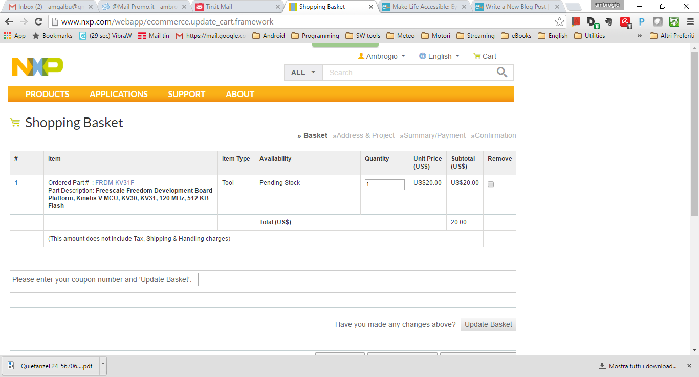
The subject of this installment is project EyeLiner by Ambrogio Galbusera (amgalbu). The goal of this project is to give the ability for disabled people to create art, even if they are paralyzed from the neck down. To do this, Ambrogio will construct a robotic drawing mechanism that is controlled by eye movement. Eye tracking will be handled by a Raspberry Pi / Pi camera combo in conjunction with the PyGaze python library. The robotic drawing platform will be controlled via the NXP’s FRDM-KV31 Freedom Development Platform and FRDM-MC-LVPMSM Low-Voltage Motor Control Kit.
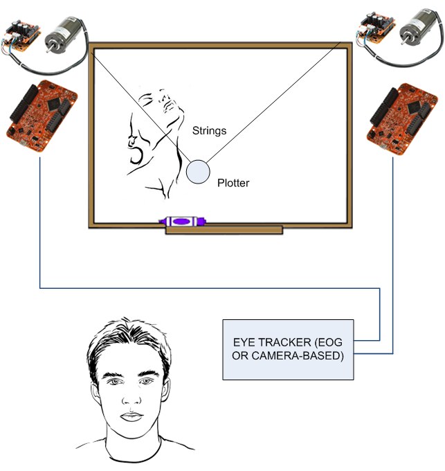
Ambrogio’s first project update laid out his plans on how he will get things up and running. The whole assembly will be controlled by a Raspberry Pi that tracks the user's pupils via the PyGaze Python library. The robotic drawing assembly will feature two FRDM-MC-LVPMSM Low-Voltage Motor Control Kits that act as a . They will be addressed individually by the NXP’s FRDM-KV31 Freedom Development Platform as it receives motion data from a Raspberry Pi. While a camera based eye tracker is the first choice, Ambrogio says that he would like to explore an EOG-based eye tracker if time allows.
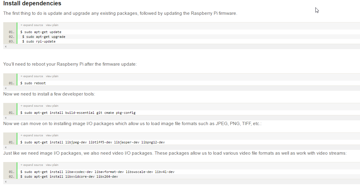
Project EyeLiner’s second and third post were all about getting the OpenCV software running on the Raspberry Pi as it is a prerequisite to getting PyGaze working correctly. Ambrogio details every step needed to get the software installed on a Raspberry Pi, including listing out all of the commands needed to get all of OpenCV’s prerequisites installed.
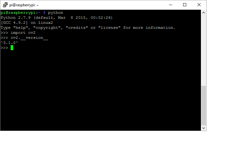
If working with OpenCV interest you, and the install intimidates you a little, these two post combine to make the perfect tutorial to follow if you are wanting to run the program on a Raspberry Pi. I really like it when I see challengers posting full instruction tutorials on installing Linux packages like this as they make it very easy for those at home to follow along with the project.

The project’s fourth update tackled more software installation, with PyGaze being the sole subject. Much like the previous two post, every step of the installation process was documented, making things much easier for people at home to replicate. Post five quickly followed, with a very helpful tutorial on how to install the Webcam Eye Tracker software. This install was a bit tricky though as the software does not work on a Raspberry Pi straight out of the box. Some modifications to the source code are needed to get things working correctly, and Ambrogio has provided the correct source code in this post.
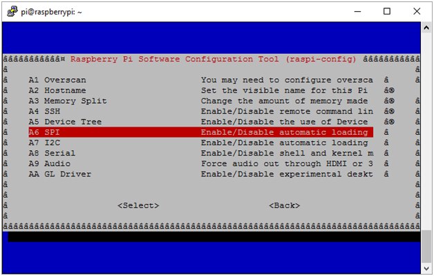
In the sixth update, Ambrogio clued us in on SPI Communication and how to get the SPI package working on Raspbian. I am sure that I have said it in the past, but I am going to say it again. Ambrogio’s project update post are exactly what I like to see in a Design Challenge. His post provide the perfect level of detail, allowing the readers at home to easily follow the project, and understand how everything works. If you are selected to be a challenger in an upcoming design challenge, I highly suggest taking an hour or so to read over Ambrogio’s post for inspiration.
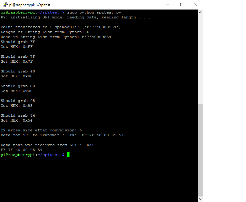
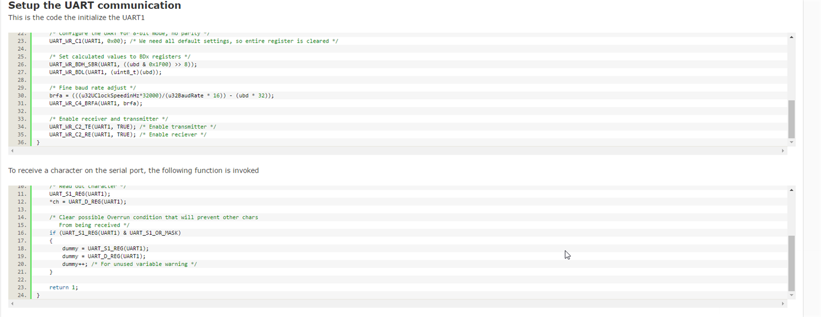
EyeTracker’s seventh update was filled with more SPI information, and taught us how to utilize the SPI protocol using Python. Even though he prefers to code his projects in C, Ambrogio chose Python for this project due to the choice to use PyGaze. He does mention that he will write a small module that will allow PyGaze to be interfaced with the SPI module that will be written in C. "I will just make a string with the hexadecimal representation of (X, Y) coordinates the pen has to move to and that’s all. To do the transformation there must first be a C program that takes in both the string data and the length of string,” Ambrogio said. “This will [guarantee] the data is being parsed out right in C as it was expected in Python.”
Update: 23 June 2016
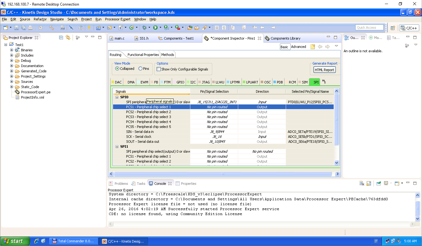
On May 7th project Eye Prints received its eighth update with Ambrogio breaking down the install and first application creation process in the Kinetis Design Studio. This post was on par with similar post from other challengers, but Ambrogio does go an extra step forward by showing the process that is needed to create your first project in the IDE. Having used KDS in the past, I can attest to this part of the process being as easy to understand as stated in this post. I would like to see Ambrogio or one of the other challengers go more into detail in their workflow process that they use with KDS.
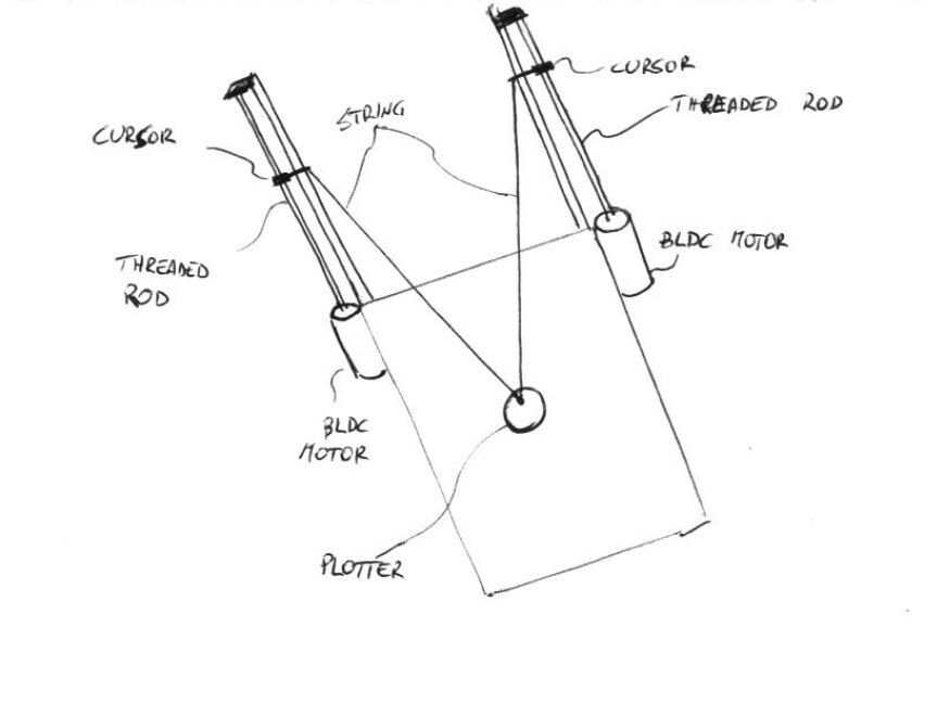
In update number nine, Ambrogio dove deeper into the mechanical design portion of the project, and finally revealed that his plotter will be based roughly around a traditional polagraph design. Instead of using the typical string and pulley design, this model will be built around threaded rods. "There are two threaded rods that will be driven by the BLDC motors. Threaded rod’s rotation will make a bolt move up and down,” Ambrogio said. “The bolt will have a string tied that will move the plotter on the drawing board. The idea of the threaded rod is just a “trick” to keep cost down: it replaces a gear box at the cost of a bigger structure layout.” This design does have a tradeoff between size and precision, and Ambrogio says that he is ok with a more precise plotter while compromising on size.
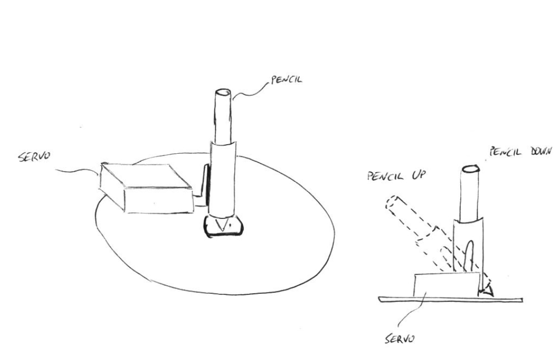
The project’s tenth update talked more about the mechanical design, this time focusing on the actual plotter itself. The purpose of the plotter is to hold a drawing instrument securely, and still be able to lift it from the paper when the polargraph is moving the plotter head to a new section of the paper. Ambrogio plans to use a servo on a tilting pen holder to accomplish this. He chose this simple design based on its low-cost and easy to build nature. “The servo will be controlled by the Raspberry Pi board. When painter blinks his or her eyes, the pencil is lifted up. When painter blinks eyes again, the pencil goes back to the vertical position,” Ambrogio concluded.
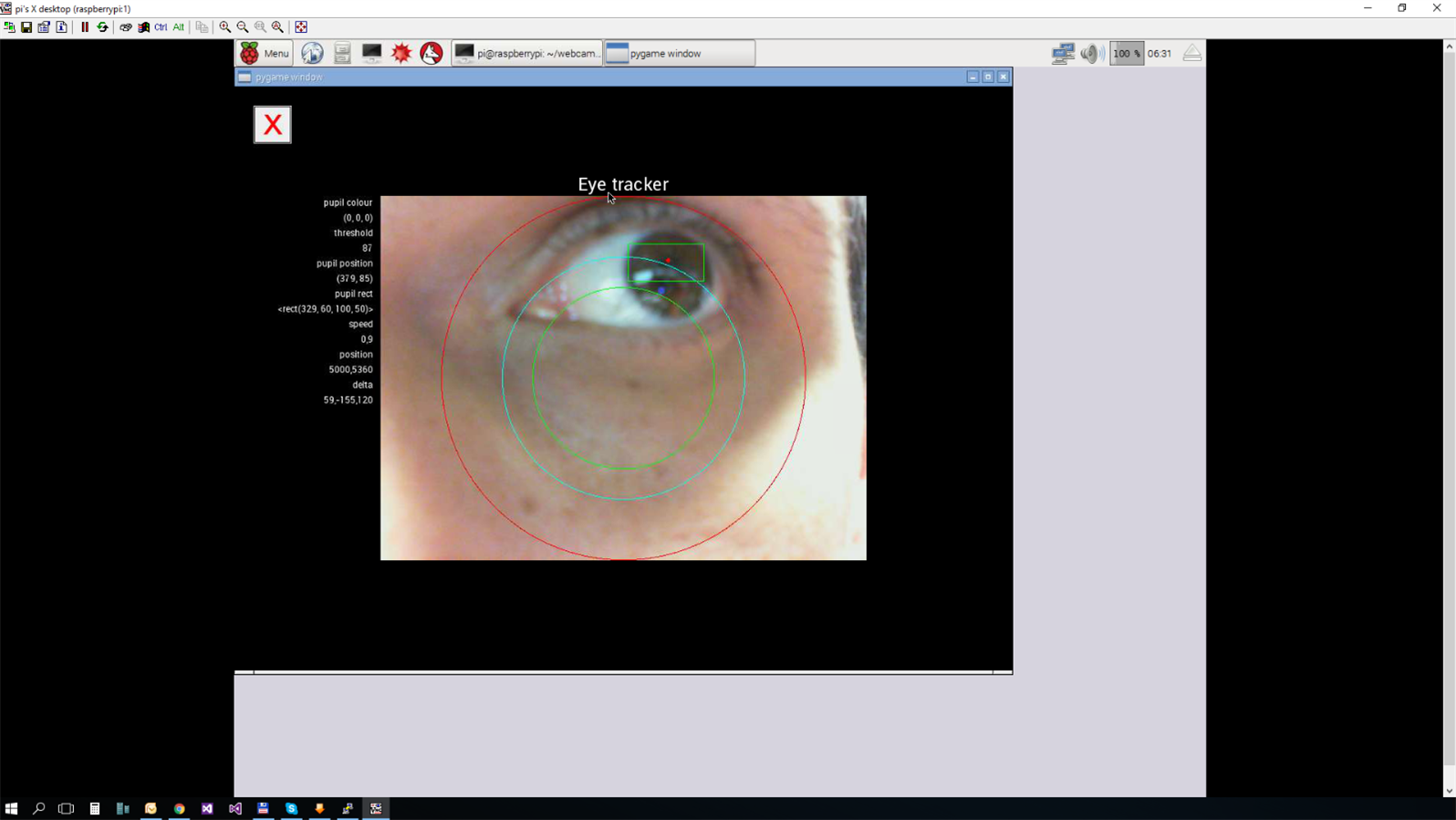
Update number eleven was all about software. In the days since his last post, Ambrogio had been hard at work writing and refining the software that he will use to track EyePrint’s user's eyes. In the image above you can see a few concentric circles. These circles are used to define where the plotter moves in relation to the eyes position and the plotters position on the paper. If the eye is centered inside the smaller green circle, the plotter stays stationary. If the user's eye moves outside of the green circles, the plotter moves in the direction the eye moved, with its speed relative to how far outside of the circles it is. For example, if the eye moves completely to the top left corner, the plotter will move very quickly in that direction. If the eye is only half way between the center circle and the top left corner it will move in that direction more slowly. Head to the link above for a more information, and a download of this software.
Getting started with the challenger kit was the basis of the twelfth update, and Ambrogio briefly explained how he will be using the Kinetis Motor Suite to control the polargraph assembly. Like many of the other challengers, Ambrogio was confused about the lack of documentation on how to wire the Linx motor that comes with the kit. Fortunately you can make out the wire colors in one of the photos on the NXP site, and that configuration proved to be correct. Ambrogio mentions that users of this development kit, “Pay attention to connect the thicker wires, since there are other green, blue and white wires for the sensor.”
Update: 24 August 2016
Update thirteen came with some unfortunate news that the program Ambrogio built in the previous post was very hard to modify, and resulted in him rebuilding the entire program from scratch. This time he used a different NXP tool called MCRSP_PMSM. This tool includes a different motor control library called, FreeMaster, which he says is much easier to use. Head over to the link above to review the changes made, and to download the sourcecode.
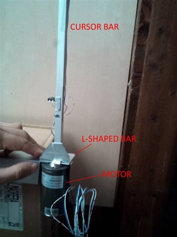

The project's main drive assembly and drawing board were the focus of update number fourteen. Ambrogio covers how he attaches the motors to the threaded rods, and how the rod is shielded in an aluminum extrusion. “Motor are fixed to an L-shaped aluminum bar. The top cover of the motor has three screw holes…” he said. “The cursor moves along a 5 mm threaded rod. The diameter is identical to the diameter of the motor shaft... The threaded rods are housed in a U-shaped aluminum bar. The bar has a 10x10 mm section, so that a bolt can slide perfectly. At the top and at the bottom of the U-shaped bar, two M6 bolts keep the threaded rod in place.“
Update number fifteen showcased the plotter’s mechanical assembly as well as the Python code that will be used to control it. As you can see from the video above, Ambrogio has came up with a very clever design, and it appears to work great. A small servo is used to tilt a piece of PVC pipe from a vertical position to a near horizontal position. This is necessary as the tip of the marker has to be lifted from the drawing surface when the plotter needs to move positions. In the final design, the lifting will be controlled by the end user blinking his or her eye.
On June 21st Ambrogio broke the sad news that he was abandoning the project due to no information about a second freedom board arriving. With so much progress made over the last few weeks, I am absolutely heartbroken that I will not get to see this project finished. I am assuming that Ambrogio needs a second Freedom board and motor controller kit for the other threaded rod that is used in his polargraph. Unfortunately he also states that he will not complete the project after the competition is over, and no working prototype will be produced. He will publish all of the source code, and while that is a major win for the open source community, I would have liked to see the project come to fruition. Either way, this was a very fun project to follow, and I wish Ambrogio the best of luck in future endeavors.

This project placed 3rd overall in the Make Life Accessible Design Challenge, and Ambrogio takes home the third place despite the project coming to an unfortunate end before the challenge was over. I am very happy to see third place awarded to Ambrogio, as I felt this project was one of the coolest, that I have seen so far in my year of covering the design challenges. Configuring an eye tracking program to control a Cartesian robot easily, and for little money was something only heard of in science fiction just a few decades ago, and here is just such a project in the real world. Congratulations Ambrogio, you deserved this, and I hope to see you participating in future challenges!
That is going to wrap up my summary coverage of project EyeLiner. This project had massive potential, and I am sure that Ambrogio was very sad to not be able to finish it. He is a very talented maker, coder, and designer, and I am sure that we will see him again at some point in the future. Thanks for taking the time to read my summary updates on this project. Tune in next week for another Design Challenge Project Summary here at Element14. Until then, Hack The World, and Make Awesome!
Top Comments