Blogs in this series
This the first post of this challenge. First of all, I will provide a brief description of the items included in the challengers kit and an overview of the project I am going to build
1. Unboxing
The N-gaged design challenge kit includes the following items
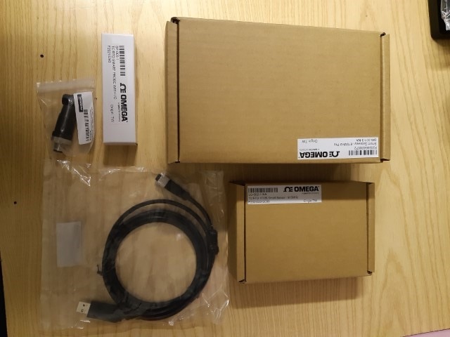
1.1 SP-005-1 Layer N M12 Modular Thermocouple and RTD Temperature Smart Probe
The Layer N SP-005 Thermocouple and RTD Smart Probe provides an easy way to integrate your thermocouple and RTD probes to the Layer N Ecosystem. The SP-005 accepts standard M12 thermocouples and RTDs through its M12 4-pin connector and Layer N Smart Interfaces through its M12 8-pin connector. The M12-S-M-FM connector (included in the provided kit) can be utilized to easily connect wire leads typically found on thermocouples or RTD probes to your SP-005.
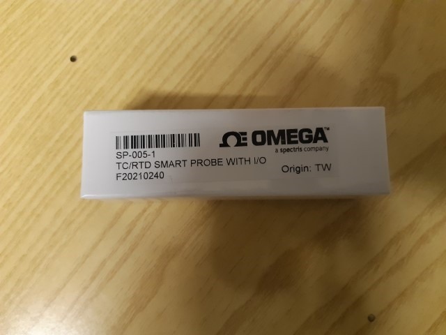
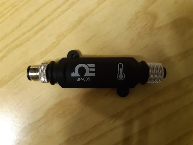
The SP-005-1 smart probe has two M12 connectors. One connector has 4 pins and can be used to connect the thermocouple. Here is a diagram of the connector

This is the straight connector included in the kit that can be used to simplify wiring
On the other end, a 8-pins connector can be used to configure the smart probe. Layer N Smart Probes require a Layer N Smart Interface to operate and connect to your Layer N Ecosystem. There are both
wired and wireless options. The challengers kit includes the wired option (IF-001). By means of this adapter, the smart probe can be connected to a PC and configured using the SYNC software

Unfortunately the kit is missing the thermocouple, so I have to get one
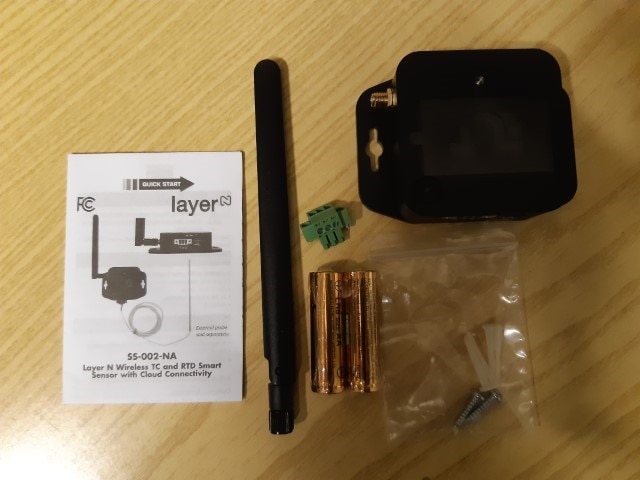
1.2 SS-002-1-NA TC/RTD+THBL Smart Sensor - 915 MHz
Layer N SS-002 Smart Sensors provide an external 3-wire RTD, thermocouple, or contact closure solution in addition to the built in suite of precision internal sensing elements that come standard with the SS-001 to accurately measure environmental conditions for a wide range of applications. The SS-002-0 offers a configurable choice of an external thermocouple, RTD, or DIN (contact closure). The SS-002-1 offers a configurable mix of any three of the four internal sensors: Temperature, Humidity, Barometric Pressure, Ambient Light, AND one external sensor option: Thermocouple, RTD, or DIN (contact closure).
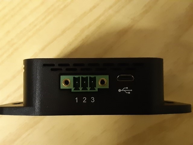
1.3 GW-001-3-NA Smart gateway 915 MHz Pro
GW-001 Series gateways are designed for long range performance and ease of use. They aggregate data from all connected sensors and transmit it to the Layer N Cloud where it can be securely accessed from your PC, tablet or phone.
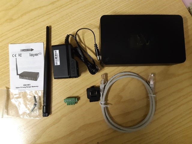
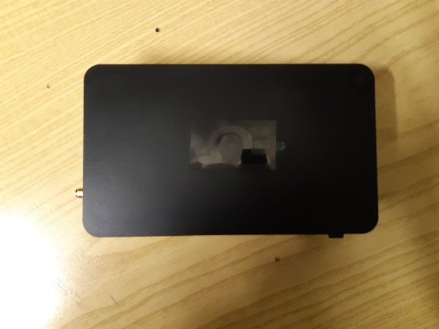
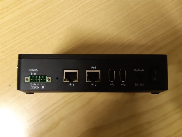
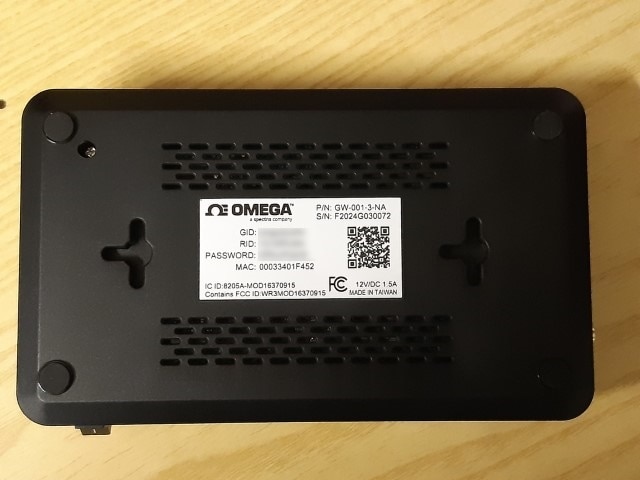
The GW-001 gateway features two ethernet ports (one with PoE support) and a 5-pins connector for serial Modbus communication and digital alarm reporting

2. Architecture
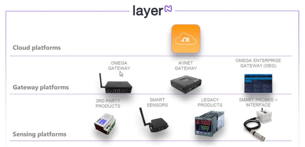
All the components in the kit are part of an ecosystem called "Layer N" that is shown in picture below
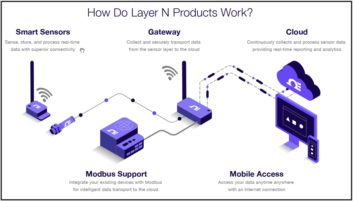
Data is collected by Smart probes (for example, the SP-005) and Smart sensors (like the SS-002). Collected data is sent to the a GW-001 gateway and, finally, sent to the Layer N cloud servers. Cloud N software suite provides convenient way to
analyze and access data from any device (from desktop PCs to mobile devices)
3. About my project
I am going to leverage the Omega Layer N features to monitor the photovoltaic system I have installed at my house
3.1 Problem description
In a photovoltaic system, it’s difficult to check whether the panels are performing as expected or there is something limiting the energy produced. Example of causes that can limit energy production are
- Components aging
- Panel covered with dust, sand, or leaves
- Cells damaged by excessive heat or hail impact
- In case more than one string is installed, blown fuses on a single string
Certain problems are easy to detect (for example, a blown fuse causes an abruptly drop in energy production). However, other slight loses in efficiency are harder to detect, because energy production is strictly related to sky conditions. For example, during cloudy days energy production is lower, but this does not imply a problem in the photovoltaic system. This is a problem I currently am facing. I have a 3kW photovoltaic system installed on the roof of my house I want to be sure everything is working as expected
3.2 Technical solution
The technical solution to this monitoring problem is to make reading of both energy production and weather conditions and correlate these two “worlds” by means of a custom-designed inference algorithm
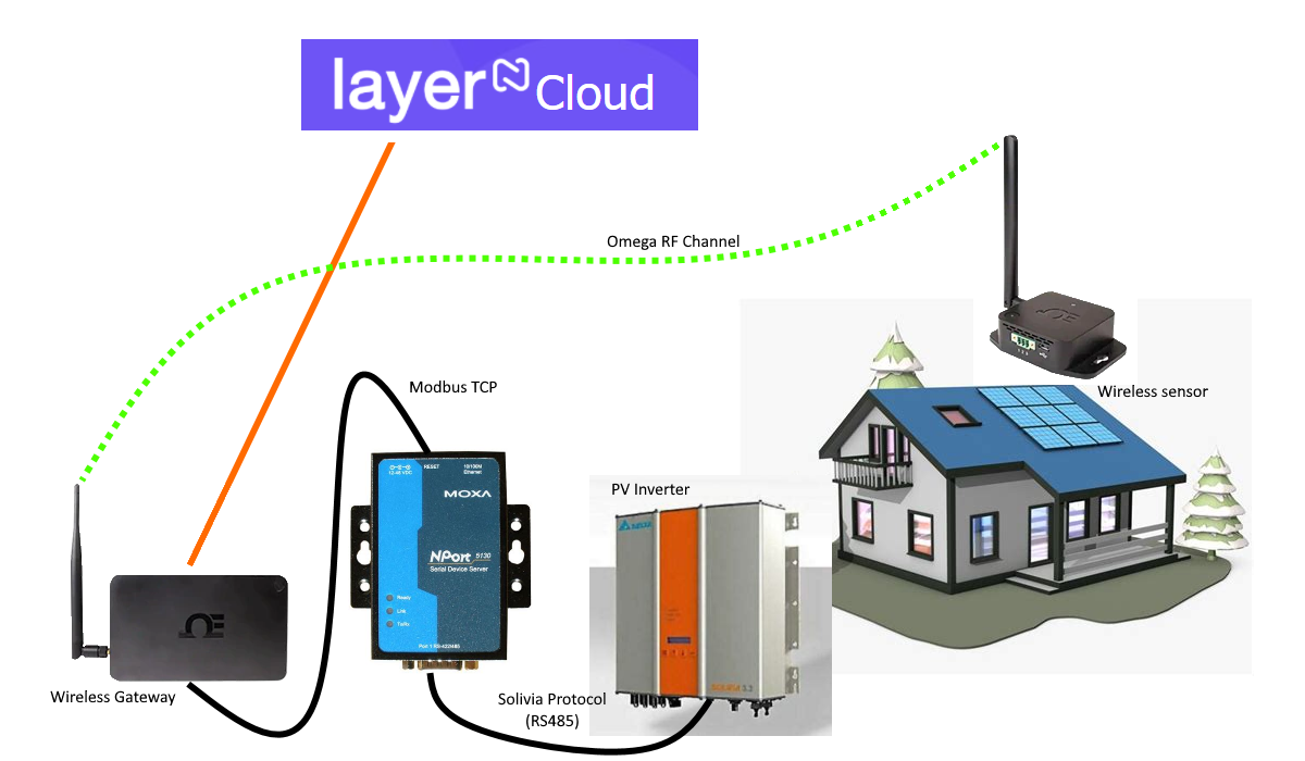
In my specific case, the inverter is a Delta Solivia, which can provide status information through a proprietary protocol over an RS485 serial bus. To interface the inverter to the Omega gateway I need to build a protocol converter.
The components of the solution are
- The Omega wireless sensor: it will be installed on the roof, close to the PV panels, in a IP67 enclosure with transparent plexyglass cover. The sensor will send temperature and light readings to the Omega wireless gateway
- The protocol converter: since the Omega wireless gateway only supports Modbus TCP protocol, I will implement a protocol converter that can read data out from the Delta Solivia inverter using the Solivia proprietary protocol and makes data available to the Omega Wireless gateway through a standard Modbus TCP protocol
- The Omega wireless gateway: it will receive data from the Omega wireless sensor and will poll the protocol converter. Collected data will be sent to the Layer N cloud server for further processing
4. Project steps
The project will be built according to the following plan
- Unboxing and test of the connectivity between Omega wireless sensor and Omega wireless gateway
- Test of the Modbus TCP connectivity between the Omega wireless gateway and a generic Modbus TCP server
- Implementation of the protocol converter
- Test of the Modbus TCP connectivity between the Omega wireless gateway and the protocol converter
- Test of cloud connectivity between the Omega wireless gateway and the Layer N cloud solution
- Implementation of the application logic (alarm and anomaly detection) in the Layer N cloud solution
- Collection of initial data for evaluation and validation of the anomaly detection algorithm

-

DAB
-
Cancel
-
Vote Up
0
Vote Down
-
-
Sign in to reply
-
More
-
Cancel
Comment-

DAB
-
Cancel
-
Vote Up
0
Vote Down
-
-
Sign in to reply
-
More
-
Cancel
Children