


Argh, Writing a good post is definitely the hard part. :D i completed interfacing all the necessary modules almost a week ago, I am also working on other projects in parallel, but this weekend, i managed to sit down and write this post. The final piece of the jigsaw in my project is to get W5500 to interface with the MAX32630.
Recap:
The idea is simple enough: stop making people swipe a card and type a PIN at every single door. Instead, the ID card (a MAX32630FTHR + ATECC508A in your pocket) unlocks once via PIN, then silently does challenge-response crypto over Bluetooth every time you walk up to a door. If the card gets yanked off you, the IMU detects the tug and it locks itself. No PIN, no entry. For more details check the Part 1 of the series
- Identity Protocol Part 1 - Plan
- Identity Protocol - Part 2 - Django Server
- Identity Protocol - Part 3 - Unboxing and Blinking with Maxim LPSDK
- Identity Protocol - Part 4 - BLE using PAN1326B and BTstack
- Identity Protocol - Part 5 - Interfacing a Keypad
- Identity Protocol - Part 6 - Snatch Detection with the BMI160 IMU
- Identity Protocol - Part 7 - Colouring on the ICLED FeatherWing
- Identity Protocol - Part 8 - Cryptographically Sign with ATECC508 and Verify with Micro-ECC
- Identity Protocol - Part 9 - BLE GATT Challenge/Response with BTstack
The SPI Protocol: Reads, Writes, and Verifying Connectivity
The SPI transaction requires three bytes of command header (address + block + direction) followed by one or more data bytes. The direction is in the control byte:
Read:  [ADDR_H][ADDR_L][BSB|READ |OM][DATA_IN_FROM_W5500...]
Write: [ADDR_H][ADDR_L][BSB|WRITE|OM][DATA_OUT_TO_W5500...]
RWB bit: 0 = read, 1 = write. OM (Operation Mode) is almost always 0 for variable-length reads/writes. BSB is the block selection bits to say which memory i want to access.
The first test is always the same: read VERSIONR (register 0x39 in the common block, BSB 0x00). The W5500 should respond as 0x04.
static int w5500_read(uint16_t addr, uint8_t *rx, int len)
{
    uint8_t tx[3] = {
        (uint8_t)(addr >> 8),                   /* ADDR_H */
        (uint8_t)(addr & 0xFF),                 /* ADDR_L */
        (W5500_BSB_COMMON << 3) | W5500_READ    /* control: BSB 0x00, READ */
    };
    return spi_read_write(tx, 3, rx, len);
}

uint8_t version = 0;
w5500_read(W5500_REG_VERSIONR, &version, 1);
if (version != 0x04) {
    printf("W5500 not responding. VERSIONR = 0x%02x\n", version);
    return -1;
}
printf("W5500 alive. VERSIONR = 0x%02x\n", version);
BSB = 0x00  Common registers // (VERSIONR, IP config etc.)
BSB = 1, 5, 9, 13... → Socket 0, 1, 2, 3... register space (status, control, RX/TX pointers)
BSB = 2, 6, 10, 14... → Socket 0, 1, 2, 3... transmit buffer
BSB = 3, 7, 11, 15... → Socket 0, 1, 2, 3... receive buffer


The formula for socket n:
Registers: BSB = (n * 4) + 1
TX buffer: BSB = (n * 4) + 2
RX buffer: BSB = (n * 4) + 3
Never on the same boat, I mean Voltage
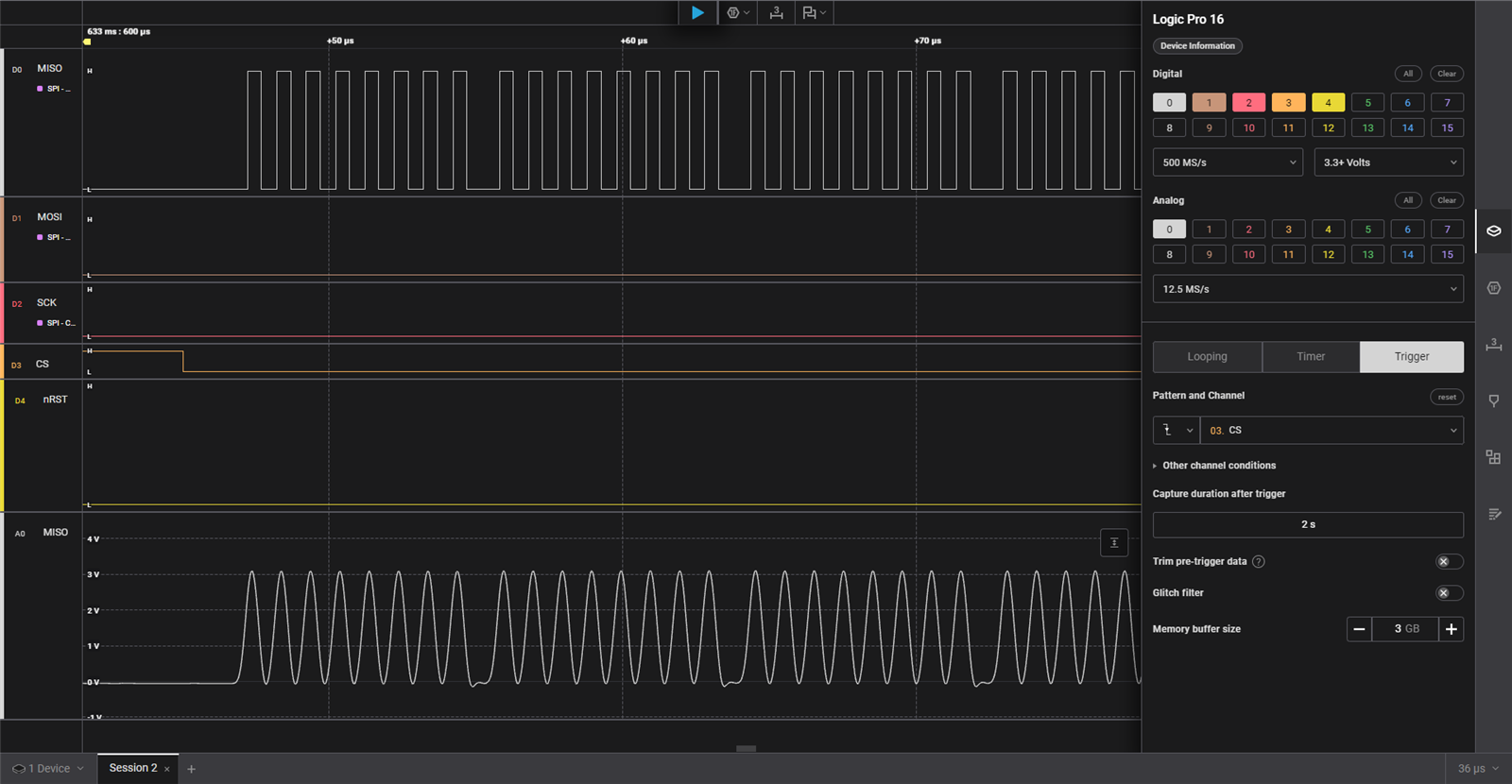
But my code was being heard on deaf ears, No response. I tried going though the documentation, it's clear as day. It should work, But it did not. So, I hooked up my logic analyzer. No signals on the clock lines. Then spend an hour trying to see why the SPI peripherals is not being initiated. I even compiled the official examples, yet no avail. But then I "Accidentally" Clicked the Analog reading of the signal lines and then i saw something like an ECG. The SPI's clock line. But the logic levels was around 1.7V. And then it hit me. The chip is communicating at 1.8V levels. But W5500 Does not respond back to such levels. So first instinct, I used TXB108 Level shifter, I checked the output lines, and it was working but W5500 Never responded. I was greeted with 0xFF
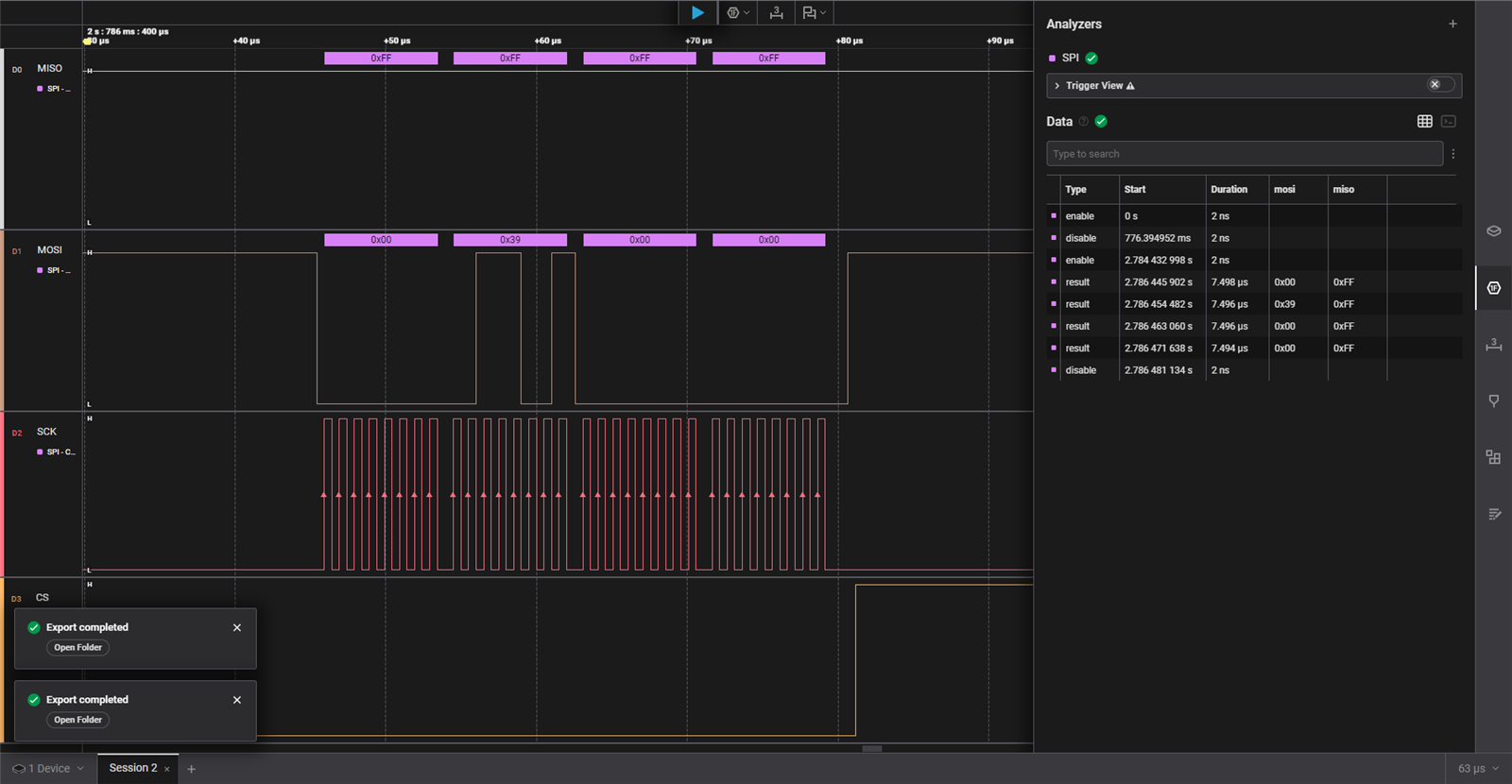
Now, what i noticed is that when i reset, the MOSI was not very consistent. Ideally it was supposed to sent 0x00 0x39 0x00 0x00 (the image above has the ideal sequence) but many times i noticed, there would be extra 0xFF in between the right sequence. I felt the level shifter had to do something to with the ghost bits, In my past, the level shifter had created issues for me. Without a reliable level shifting, I was stuck, But then i remembered the MAX32630 was working fine with the I2C lines which was pulled up to 3.3V which means it is 3.3V tolerant, so i dug into the documentation to find, i can change the Logic level of the Pins on an individual level. Whoa is what i said,
By changing the IOMAN has select bits to move a pins output buffer to another voltage level (use_vddioh_0/1/2). By calling SYS_IOMAN_UseVDDIOH(&cfg) after SPIM_Init, I get a 3.3V SPI Signals
const spim_cfg_t spim_cfg = { .mode=0, .ssel_pol=SPIM_SSEL0_LOW, .baud=1000000 };
SPIM_Init(MXC_SPIM2, &spim_cfg, &sys_cfg);

const gpio_cfg_t spim2_vddioh = {
    PORT_5, (PIN_0 | PIN_1 | PIN_2 | PIN_3),
    GPIO_FUNC_GPIO, GPIO_PAD_NORMAL
};
SYS_IOMAN_UseVDDIOH(&spim2_vddioh);
Careful enough to change only the SPI lines i tried again and It is alive. W5500 was talking back 0x40.

Back to SPI Protocol
To write a register, i use
static int w5500_write(uint16_t addr, const uint8_t *tx, int len)
{
    uint8_t cmd[3] = {
        (uint8_t)(addr >> 8),
        (uint8_t)(addr & 0xFF),
        (W5500_BSB_COMMON << 3) | W5500_WRITE   /* BSB 0x00, WRITE */
    };
    return spi_write(cmd, 3, tx, len);
}

uint8_t mac[6] = {0x00, 0x08, 0xDC, 0xAB, 0xCD, 0xEF};
w5500_write(W5500_REG_SHAR, mac, 6);            /* set source hardware address */
To read a socket register, i use the the code below with the BSB calulated as per the code above
int sreg_read(int socket, uint16_t offset, uint8_t *rx, int len)
{
    uint16_t addr = offset;
    uint8_t bsb = W5500_BSB_SREG(socket);   /* computes (socket*4)+1 */
    uint8_t tx[3] = {
        (uint8_t)(addr >> 8),
        (uint8_t)(addr & 0xFF),
        (bsb << 3) | W5500_READ
    };
    return spi_read_write(tx, 3, rx, len);
}

uint8_t sr;
sreg_read(0, Sn_SR, &sr, 1);   /* read socket 0 status register */
if (sr == SOCK_ESTABLISHED) {
    /* socket is connected */
}
TCP: Open, Connect, Send, Receive, Close
The W5500 has a simple socket abstraction. Each operation sets a CR (Command Register) value and polls the SR (Status Register) for the result/
| Step | Write CR | Poll SR until | Timeout |
|---|---|---|---|
| Open | CR_OPEN |
SOCK_INIT |
100 ms |
| Connect | CR_CONNECT |
SOCK_ESTABLISHED |
5 s |
| Send | CR_SEND |
Sn_IR.SEND_OK |
1 s |
| Recv | (no cmd) | Sn_RX_RSR > 0 |
per attempt |
| Close | CR_DISCON then CR_CLOSE |
SOCK_CLOSED |
200 ms |
The So i code tcp_recv, which reads in a loop until either the buffer fills or the remote closes the connection and yes, i used HTTP1 which i copied from the regular arduino library.
static int tcp_recv(int sn, uint8_t *buf, int max_len)
{
    int total = 0;
    for (int idle = 0; idle < 100 && total < max_len; idle++) {
        uint16_t avail = sreg_r16(sn, Sn_RX_RSR);
        if (avail == 0) {
            uint8_t sr = sreg_r8(sn, Sn_SR);
            if (sr == SOCK_CLOSE_WAIT || sr == SOCK_CLOSED) break;
            TMR_Delay(MXC_TMR0, MSEC(50));
            continue;
        }
        int n = avail;
        if (total + n > max_len) n = max_len - total;
        uint16_t rd = sreg_r16(sn, Sn_RX_RD);
        srx_read(sn, rd, buf + total, n);
        sreg_w16(sn, Sn_RX_RD, rd + (uint16_t)n);
        sreg_w8(sn, Sn_CR, CR_RECV);
        total += n;
        idle = 0;
    }
    return total;
}
I did use static ip configuration for my LAN, and copied more and more working from the arduino library to interface the actual requests. Explaining that will be far too gruesome and more sleep inducing than Propofol So i will end it here. Now for the 3D printing and integration
Final Notes
When you are used to Arduino Libraries for quick prototyping, you forget to appreciate the work done by the developers to get these things working. Even porting an existing code to a diferent platform to make it work the SDK is a huge task. So respects to the Developers. Now, truth be told, My code is bit flaky and does not work 20% of the time, I am not going to solve this considering the timeline. But i will take it as a good enough work for the final integration and solve it there if needed.
