


How to make an MSP432 LaunchPad talk i2c to a DAC.
This TI-RTOS program tells the DAC to output a sine wave. It could be something else but I reused an existing Arduino sketch. |
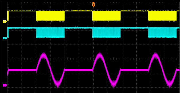
In my previous i2c example, the focus was on reading data from a sensor. This one only writes data out. t's not intended to be a useful application, just a test bed to see if the DAC that I have here is listening properly.
The schema and code are derived from work of Robert Peter Oakes:
The Modular Bench Power Supply ++, Arduino UNO and precision ADC, DAC + MDO3000 I2C debugging
Raspberry PI 2, Fun with I2C DACs and ADC's
If you understand Arduino sketches, look there to understand how the program works. The code below is a fairly true port to TI-RTOS.
Schema

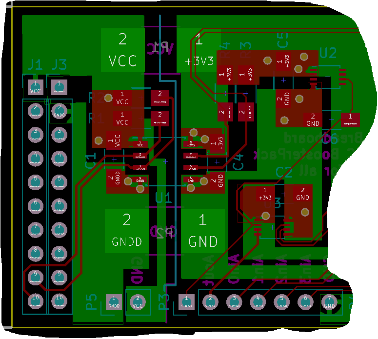
You can see a BoosterPack in the making here.
The difference with Peter's schema is that I'm using a single DAC (DAC8571). He uses a quad DAC in a single chip. Doesn't matter for this exercise.
Key take-aways from the schema is that we can use the MSP432 to set the output voltage of the DAC.
A voltage reference REF5020 helps the DAC to improve its performance. We don't talk to that chip, it just does its work by being there.
You can think away the i2c isolator ic (ISO1541). It's there to save the laptop's USB port when something happens downstream.
Firmware
I've copied my own project from the first i2c blog and replaced the part that talks to a temperature sensor with Peter's DAC Arduino code.
#define DAC_I2C_ADDR           (0x4C)
#define DAC_I2C               MSP_EXP432P401R_I2CB0

uint16_t Sin_tab[256] = {  32768,33572,34376,35178,35980,36779,37576,38370,39161,39947,40730,41507,42280,
                               43046,43807,44561,45307,46047,46778,47500,48214,48919,49614,50298,50972,51636,
                               52287,52927,53555,54171,54773,55362,55938,56499,57047,57579,58097,58600,59087,
                               59558,60013,60451,60873,61278,61666,62036,62389,62724,63041,63339,63620,63881,
                               64124,64348,64553,64739,64905,65053,65180,65289,65377,65446,65496,65525,65535,
                               65525,65496,65446,65377,65289,65180,65053,64905,64739,64553,64348,64124,63881,
                               63620,63339,63041,62724,62389,62036,61666,61278,60873,60451,60013,59558,59087,
                               58600,58097,57579,57047,56499,55938,55362,54773,54171,53555,52927,52287,51636,
                               50972,50298,49614,48919,48214,47500,46778,46047,45307,44561,43807,43046,42280,
                               41507,40730,39947,39161,38370,37576,36779,35980,35178,34376,33572,32768,31964,
                               31160,30358,29556,28757,27960,27166,26375,25589,24806,24029,23256,22490,21729,
                               20975,20229,19489,18758,18036,17322,16617,15922,15238,14564,13900,13249,12609,
                               11981,11365,10763,10174,9598,9037,8489,7957,7439,6936,6449,5978,5523,5085,4663,
                               4258,3870,3500,3147,2812,2495,2197,1916,1655,1412,1188,983,797,631,483,356,247,
                               159,90,40,11,1,11,40,90,159,247,356,483,631,797,983,1188,1412,1655,1916,2197,
                               2495,2812,3147,3500,3870,4258,4663,5085,5523,5978,6449,6936,7439,7957,8489,9037,
                               9598,10174,10763,11365,11981,12609,13249,13900,14564,15238,15922,16617,17322,
                               18036,18758,19489,20229,20975,21729,22490,23256,24029,24806,25589,26375,27166,
                               27960,28757,29556,30358,31160,31964};
Paste these lines of code in that previous i2c example, before the definition of the RTOS task.
The first two lines define the i2c address of the DAC ic and the i2c port f the MSP432 that we'll use.
The Sin_tab is an array with sine wave sample values. Try to paste these values in Excel and make a line graph. You'll see what's happening in there.
Then replace the existing RTOS task with this one:
Void taskFxn(UArg arg0, UArg arg1)
{
    unsigned int    i;

    uint8_t         txBuffer[3];
    uint8_t         rxBuffer[2];
    I2C_Handle      i2c;
    I2C_Params      i2cParams;
    I2C_Transaction i2cTransaction;


    /* Create I2C for usage */
    I2C_Params_init(&i2cParams);
    i2cParams.bitRate = I2C_400kHz;
    i2c = I2C_open(DAC_I2C, &i2cParams);
    if (i2c == NULL) {
        System_abort("Error Initializing I2C\n");
    }
    else {
        System_printf("I2C Initialized!\n");
    }

    i2cTransaction.slaveAddress = DAC_I2C_ADDR;
    i2cTransaction.writeBuf = txBuffer;
    i2cTransaction.writeCount = 3;
    i2cTransaction.readBuf = rxBuffer;
    i2cTransaction.readCount = 0;

    txBuffer[0] = 0x10;

    while (1) {
        for (i = 0; i< 256; i++) {
            txBuffer[1] = Sin_tab[i] >> 8;
            txBuffer[2] = Sin_tab[i];
            if (I2C_transfer(i2c, &i2cTransaction)) {
            }
            else {
                System_printf("I2C Bus fault\n");
                System_flush();
            }
        }
        Task_sleep(10);
    }

    /* Deinitialized I2C */
    I2C_close(i2c);
    System_printf("I2C closed!\n");
    System_flush();
}
The code iterates the array, sends each value to the DAC until it reaches the end.
Then we yield to the RTOS for a while to give other tasks (there aren't any  ) the chance to execute, and start all over.
Now pull out the datasheet of the DAC. The combination of code and specifications show the full picture of this example.
This translates to the address 0x4C:
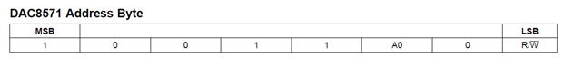
#define DAC_I2C_ADDR (0x4C)
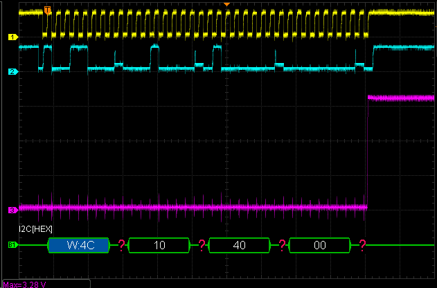
And these three bytes say: set the output value (byte 0 is the command, 1 the most significant byte of the 16 bit value, 2 the least significant one.

    txBuffer[0] = 0x10;

    while (1) {
        for (i = 0; i< 256; i++) {
            txBuffer[1] = Sin_tab[i] >> 8;
            txBuffer[2] = Sin_tab[i];
Top Comments