element14 Community
element14 Community
    Register Log In
  • Site
  • Search
  • Log In Register
  • About Us
  • Community Hub
    Community Hub
    • What's New on element14
    • Feedback and Support
    • Benefits of Membership
    • Personal Blogs
    • Members Area
    • Achievement Levels
  • Learn
    Learn
    • Ask an Expert
    • eBooks
    • element14 presents
    • Learning Center
    • Tech Spotlight
    • STEM Academy
    • Webinars, Training and Events
    • Learning Groups
  • Technologies
    Technologies
    • 3D Printing
    • FPGA
    • Industrial Automation
    • Internet of Things
    • Power & Energy
    • Sensors
    • Technology Groups
  • Challenges & Projects
    Challenges & Projects
    • Design Challenges
    • element14 presents Projects
    • Project14
    • Arduino Projects
    • Raspberry Pi Projects
    • Project Groups
  • Products
    Products
    • Arduino
    • Avnet Boards Community
    • Dev Tools
    • Manufacturers
    • Multicomp Pro
    • Product Groups
    • Raspberry Pi
    • RoadTests & Reviews
  • Store
    Store
    • Visit Your Store
    • Choose another store...
      • Europe
      •  Austria (German)
      •  Belgium (Dutch, French)
      •  Bulgaria (Bulgarian)
      •  Czech Republic (Czech)
      •  Denmark (Danish)
      •  Estonia (Estonian)
      •  Finland (Finnish)
      •  France (French)
      •  Germany (German)
      •  Hungary (Hungarian)
      •  Ireland
      •  Israel
      •  Italy (Italian)
      •  Latvia (Latvian)
      •  
      •  Lithuania (Lithuanian)
      •  Netherlands (Dutch)
      •  Norway (Norwegian)
      •  Poland (Polish)
      •  Portugal (Portuguese)
      •  Romania (Romanian)
      •  Russia (Russian)
      •  Slovakia (Slovak)
      •  Slovenia (Slovenian)
      •  Spain (Spanish)
      •  Sweden (Swedish)
      •  Switzerland(German, French)
      •  Turkey (Turkish)
      •  United Kingdom
      • Asia Pacific
      •  Australia
      •  China
      •  Hong Kong
      •  India
      •  Korea (Korean)
      •  Malaysia
      •  New Zealand
      •  Philippines
      •  Singapore
      •  Taiwan
      •  Thailand (Thai)
      • Americas
      •  Brazil (Portuguese)
      •  Canada
      •  Mexico (Spanish)
      •  United States
      Can't find the country/region you're looking for? Visit our export site or find a local distributor.
  • Translate
  • Profile
  • Settings
Safe and Sound
  • Challenges & Projects
  • Design Challenges
  • Safe and Sound
  • More
  • Cancel
Safe and Sound
Blog MSP432 and TI-RTOS: Getting Started Pt. 2 - Add an ADC Sample Task
  • Blog
  • Forum
  • Documents
  • Polls
  • Files
  • Events
  • Mentions
  • Sub-Groups
  • Tags
  • More
  • Cancel
  • New
  • Share
  • More
  • Cancel
Group Actions
  • Group RSS
  • More
  • Cancel
Engagement
  • Author Author: Jan Cumps
  • Date Created: 3 Jan 2017 11:32 AM Date Created
  • Views 2323 views
  • Likes 8 likes
  • Comments 7 comments
  • safe and sound
  • msp432
  • ti-rtos
  • launchpad
  • ti_rt
Related
Recommended

MSP432 and TI-RTOS: Getting Started Pt. 2 - Add an ADC Sample Task

Jan Cumps
Jan Cumps
3 Jan 2017

Part 2 in a series that gets you RTOS-ready for the MSP432 LaunchPad


image


When you complete this example, you have a basic RTOS setup that integrates USB, ADC and a blinky. You can use Tasks, Semaphores and a UART interrupt. And you'll know how to register Tasks in the TI-RTOS configuration editor.


Part 1 sets up the project, explains how to configure a task and gets the Blinky running.

Part 2 adds an ADC Sample Task.


What you need:

  • MSP432 LaunchPad
  • 1 micro-USB cable
  • Code Composer Studio
  • TI-RTOS for MSP43X
  • two potentiometers (say 10K or more, not critical), a little breadboard and a few wires


We're staring where we stopped in part 1. We'll add a task that samples two ADC pins.

The results get logged to the Code Composer Studio console.

We'll use two potentiometers to set and change the voltage on the two ADC pins.


Configure the ADC Driver in RTOS

First, let's set our sample strategy in the source file MSP_EXP432P401R.c.

This file standard has different settings for ADC0 and ADC1. Let's make them the same for this exercise.


/* ADC configuration structure */
const ADCMSP432_HWAttrs adcMSP432HWAttrs[MSP_EXP432P401R_ADCCOUNT] = {
    {
        .channel = ADC_INPUT_A0,
        .gpioPort = GPIO_PORT_P5,
        .gpioPin = GPIO_PIN5,
        .gpioMode = GPIO_TERTIARY_MODULE_FUNCTION,
        .refVoltage = REF_A_VREF2_5V,
        .resolution = ADC_14BIT
    },
    {
        .channel = ADC_INPUT_A1,
        .gpioPort = GPIO_PORT_P5,
        .gpioPin = GPIO_PIN4,
        .gpioMode = GPIO_TERTIARY_MODULE_FUNCTION,
        .refVoltage = REF_A_VREF2_5V,
        .resolution = ADC_14BIT
    }
};


The ADC reference voltage is 2.5V - when testing the exercise later, don't supply more than 2.5V on the pins.

They can take 3.3V, but you'll get an overflow as soon as you exceed the reference voltage.


In the main() function in datalogger.c, add the ADC driver initialisation.


int main(void)
{
    /* Call board init functions */
    Board_initGeneral();
    Board_initGPIO();
    Board_initADC();
    // ...


This is a good time to build and run the project. It should compile without errors and the LED should blink as it did in part 1.


Add the ADC Task


The ADC task will run every 10 seconds, sample the two ADC pins and log the results to the CCS console.

Then it gives control back to RTOS, so that it can spend time to other activities (or go idle and put the controller to a lower power mode).

But first our task configeres the two ADC pins.


Create a new source file adc_sample.c.

Enter this code in that file.

/* XDCtools Header files */
#include <xdc/std.h>
#include <xdc/runtime/System.h>
#include <xdc/runtime/Error.h>

/* BIOS Header files */
#include <ti/sysbios/BIOS.h>
#include <ti/sysbios/knl/Task.h>
#include <ti/sysbios/knl/Clock.h>

/* TI-RTOS Header files */
#include <ti/drivers/ADC.h>

/* Example/Board Header files */
#include "Board.h"

/*
 *  ======== taskAdcSample ========
 *  Open an ADC instance and get a sampling result from a one-shot conversion.
 */
Void taskAdcSample(UArg arg0, UArg arg1)
{
    ADC_Handle   adc0;
    ADC_Handle   adc1;
    ADC_Params   params;
    uint16_t adcValue0;
    uint16_t adcValue1;
    ADC_Params_init(&params);
    adc0 = ADC_open(Board_ADC0, &params);
    adc1 = ADC_open(Board_ADC1, &params);

    while (1) {
        Task_sleep(((UInt)arg0) / Clock_tickPeriod);
        /* Blocking mode conversion */
        ADC_convert(adc0, &adcValue0);
        ADC_convert(adc1, &adcValue1);
        System_printf("Sample %u:%u\n", adcValue0, adcValue1);
        /* SysMin will only print to the console when you call flush or exit */
        System_flush();
    }
    // theoretically close the ADC driver. This code is never reached
//    ADC_close(adc0);
//    ADC_close(adc1);
}


Then add the task to the RTOS configuration. Open the editor by double-clicking datalogger.cfg.


image

Save all files and rebuild.

You can execute the program. It will give random-ish readouts in the console because there's nothing connected to the ADC pins yet.
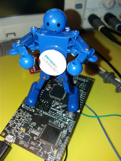
 

Hardware


Put your two potentiometers on the breadboard. Their value isn't that important. Anything between 10K and 1M is certainly ok. They don't need to have the same value. Whatever you have at home.

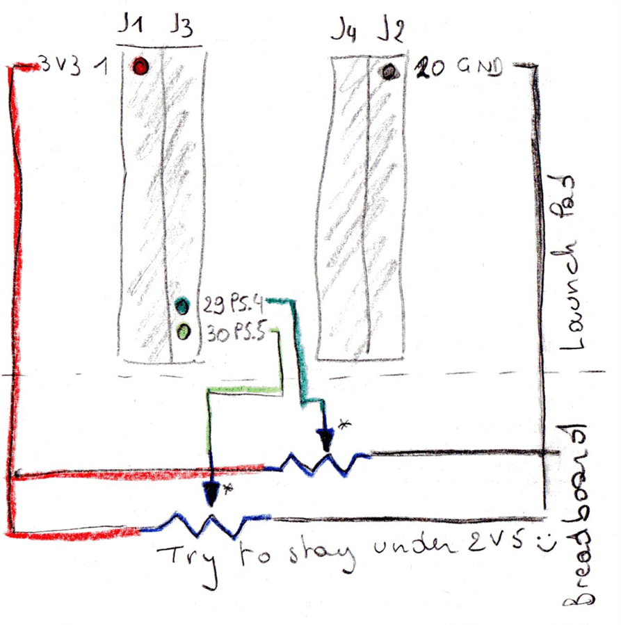
We'll use them to divide the 3V3 level of the launchpad, and send the value at the potentiometer's wiper to ADC0 and ADC1.


Wire the 3V3 of your LaunchPad to one sie of each potentiometer, GND to the other side.

The wiper of one goes to P5.4 and P5.5.


image


Set both potentiometers to the middle, plug the LaunchPad in the USB and start a debug session.

You'll see the values appear in the console.


Turn the potentiometers to see the values change. Once the wiper is above the reference value 2.5V, the results will not change because you've overrun the range.
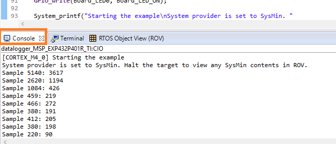
 

image


Result


[CORTEX_M4_0] Starting the example
System provider is set to SysMin. Halt the target to view any SysMin contents in ROV.
Sample 5140: 3617
Sample 2620: 1194
Sample 1084: 426
Sample 459: 219
Sample 466: 272
Sample 380: 191
Sample 412: 205
Sample 380: 198
Sample 220: 90
Sample 220: 118
Sample 348: 303
Sample 259: 215
Sample 188: 91
Sample 211: 123
Sample 380: 223
Sample 233: 137
Sample 316: 165
Sample 252: 97
Sample 444: 209
Sample 230: 94
Sample 261: 61
Sample 380: 130
Sample 412: 211
Sample 207: 103
Sample 252: 95
Sample 252: 136


TI-RTOS Series
MSP432 and TI-RTOS: Getting Started Pt. 1 - Set Up and 1st RTOS Task
MSP432 and TI-RTOS: Getting Started Pt. 2 - Add an ADC Sample Task
MSP432 and TI-RTOS: Getting Started Pt. 3 - USB with Minimal CPU Use
MSP432 and TI-RTOS: PWM
MSP432 and TI-RTOS: I2C Configuration for Sensors BoosterPack
MSP432 and TI-RTOS: another I2C example - talk to a DAC
MSP432 and TI-RTOS: Sharp LCD BoosterPack
MSP432 and TI-RTOS: PID Library Part 1 - Intro
MSP432 and TI-RTOS: PID Library Part 2 - Real World Example
  • Sign in to reply

Top Comments

  • Jan Cumps
    Jan Cumps over 8 years ago +1
    Debug and real-time scheduling don't play well together. But there's more than that that can go wrong. can you upload your project somewhere? it makes it easier to replicate your situation.
  • fredws
    fredws over 7 years ago +1
    Thought while I was at it, I looked at timing in adc routine with printing and without printing. Routine takes at least 60 microseconds to process an ADC convert routine. With the print routine, it takes…
  • Jan Cumps
    Jan Cumps over 7 years ago in reply to fredws

    fredws, for serial I/O, the buffered UART module combined with interrupts can be tuned better than _printf() and _flush() approach.

    MSP432 and TI-RTOS: Getting Started Pt. 3 - USB with Minimal CPU Use

    • Cancel
    • Vote Up 0 Vote Down
    • Sign in to reply
    • More
    • Cancel
  • fredws
    fredws over 7 years ago

    Thought while I was at it, I looked at timing in adc routine with printing and without printing.

    Routine takes at least 60 microseconds to process an ADC convert routine.

    With the print routine, it takes at least 220 microseconds, but not sure if this is just passing the printed value out of the routine or actually finishing printing it out the Serial Port.


    I am trying to get 1 millisecond and faster ADC readings using this method on a sampled period, so I am looking at this timing carefully.


    So 1/0.000060 seconds = 16,666 readings per second maximum implementing it this way assuming no other interrupts.  Obviously, you cannot go this fast if you want your program to do something else.


    Red Stars, comment in or comment out for this test, found in the adc_sample.c routine in this pages examples.

    image

    image

    • Cancel
    • Vote Up +1 Vote Down
    • Sign in to reply
    • More
    • Cancel
  • fredws
    fredws over 7 years ago

    In case anyone is wondering, the clock Module shows the Tick period (us).

    This is default to 1000 microseconds per tick generated, or one Tick per millisecond.

    This 1 millisecond rate is what Is used as a time source for the Task Argument 0 value in this example.

    so ADC Task Argument 0 = 10000 related to 10,000 milliseconds if used with Task_sleep((UInt)arg0);


    image

    • Cancel
    • Vote Up 0 Vote Down
    • Sign in to reply
    • More
    • Cancel
  • fredws
    fredws over 7 years ago

    ===================  added Extra comment with RTOS Execution Graphs ==================

    So, RTOS Analyzer - Execution Graph with Argument 0 = 10,000,000

    Pulses are spaced 10 seconds apart, graph shows heartBearFxn at 1 second, really can't see taskAdcSample at 10 seconds, but at 30 second mark on graph, if I zoom in, I can see the Adc and heartbeat.  I would have to let this run much longer to get more sample to see this.

    image


    So, RTOS Analyzer - Execution Graph with Argument 0 = 10,000

    Pulses are spaced 10 milli-seconds apart

    image

    You can setup RTOS Analyzer from Tools > RTOS Analyzer > Execution Graph.

    You have to run it once to set it up, then the next time it should look like this.

    image

    In the .cfg file to enable logging, find the BIOS_logsEnabled = true; and comment It in, comment out the false one.

    //BIOS.runtimeCreatesEnabled = false;

    /*
    * Enable logs in the BIOS library.
    *
    * Pick one:
    *  - true (default)
    *      Enables logs for debugging purposes.
    *  - false
    *      Disables logging for reduced code footprint and improved runtime
    *      performance.
    */
    BIOS.logsEnabled = true;
    //BIOS.logsEnabled = false;


    At end of .cfg file, add this text to get information you are looking for:

    // Added at the end of the file
    /* FWS commented here and added below for RTOS Analyzer - extra things I added to show on RTOS Execution Graph */
    // Select what you want to see in your RTOS Analyzer. 
    // LoggingSetup.sysbiosTaskLogging = true;    // shows Tasks if true
    // LoggingSetup.sysbiosHwiLogging = true;     // shows HWI's and Clock if = true
    // LoggingSetup.sysbiosSwiLogging = true;     // shows SWI's if true

    /* FWS Add for RTOS Analyzer - also comment in BIOS.logsEnabled = true; comment out =false about line 275 */
    var LoggingSetup = xdc.useModule('ti.uia.sysbios.LoggingSetup');
    LoggingSetup.sysbiosTaskLogging = true;   // optional, shows Tasks if true
    // LoggingSetup.sysbiosHwiLogging = true;  // optional, shows HWI's and Clock if = true
    // LoggingSetup.sysbiosSwiLogging = true;  // optional, shows SWI's if true
    LoggingSetup.mainLogging = true;   // optional, not sure what this logs, FWS. Hoping for IDLE.

    LoggingSetup.sysbiosLoggerSize = 1024;
    LoggingSetup.loadLogging = false;

    • Cancel
    • Vote Up 0 Vote Down
    • Sign in to reply
    • More
    • Cancel
  • fredws
    fredws over 7 years ago

    First off, great example.

    I started with resource explorer using SimpleLink example as shown.

    TI-RTOS Kernel (SYS_BIOS), hello > TI-RTOS > CCS Compiler > hello project.

    image


    Alternate Starting Program with TI seems to direct you away from for new projects was the empty project used to start this example under the TI-RTOS for MSP430, there is a MSP432 folder under it.

    image


    Problem with 10 second interval in ADC routine.


    Note in step 1, previous web site, GUI .cfg shows  Argument 0 =  10,000,000

    image

    In this web page, step 2, you enter 10000.

    image


    Your Task_Sleep(((UInt)arg0)/Clock_tickPeriod); The Task_Sleep(value); function is using the value entered as system clock period ticks.

    so, Clock_tickPeriod is set in GUI .cfg as 1000   microseconds  (this is 1 millisecond)

    Your Arg0 was set to 10000 in this  step.

    10000/1000 = 10 milliseconds

    If your Arg0 was 10000000 then 10000000/1000 = 10,000 milliseconds or 10 seconds.


    You could also change the code to:


    Task_Sleep((UInt)Arg0);          // this now Sleeps for Arg0 clock tick period, so Arg0=10000, wait 10 seconds.


    /*

    • *  ======== taskAdcSample ========
    • *  Open an ADC instance and get a sampling result from a one-shot conversion.
    • */ 
    • Void taskAdcSample(UArg arg0, UArg arg1) 
    • { 
    •     ADC_Handle   adc0; 
    •     ADC_Handle   adc1; 
    •     ADC_Params   params; 
    •     uint16_t adcValue0; 
    •     uint16_t adcValue1; 
    •     ADC_Params_init(&params); 
    •     adc0 = ADC_open(Board_ADC0, &params); 
    •     adc1 = ADC_open(Board_ADC1, &params); 
    •  
    •  
    •     while (1) { 
    •         Task_sleep(((UInt)arg0) / Clock_tickPeriod); 
    •         /* Blocking mode conversion */ 
    •         ADC_convert(adc0, &adcValue0); 
    •         ADC_convert(adc1, &adcValue1); 
    •         System_printf("Sample %u:%u\n", adcValue0, adcValue1); 
    •         /* SysMin will only print to the console when you call flush or exit */ 
    •         System_flush(); 
    •     } 
    •     // theoretically close the ADC driver. This code is never reached 
    • //    ADC_close(adc0); 
    • //    ADC_close(adc1); 
    • } 


    Note main c file

    Task_sleep Is this way.

    /*

    • *  ======== heartBeatFxn ========
    • *  Toggle the Board_LED0. The Task_sleep is determined by arg0 which
    • *  is configured for the heartBeat Task instance.
    • */ 
    • Void heartBeatFxn(UArg arg0, UArg arg1) 
    • { 
    •     while (1) { 
    •         Task_sleep((UInt)arg0); 
    •         GPIO_toggle(Board_LED0); 
    •     } 
    • } 

    Hope this helps others looking at this example.

    • Cancel
    • Vote Up 0 Vote Down
    • Sign in to reply
    • More
    • Cancel
>
element14 Community

element14 is the first online community specifically for engineers. Connect with your peers and get expert answers to your questions.

  • Members
  • Learn
  • Technologies
  • Challenges & Projects
  • Products
  • Store
  • About Us
  • Feedback & Support
  • FAQs
  • Terms of Use
  • Privacy Policy
  • Legal and Copyright Notices
  • Sitemap
  • Cookies

An Avnet Company © 2025 Premier Farnell Limited. All Rights Reserved.

Premier Farnell Ltd, registered in England and Wales (no 00876412), registered office: Farnell House, Forge Lane, Leeds LS12 2NE.

ICP 备案号 10220084.

Follow element14

  • X
  • Facebook
  • linkedin
  • YouTube