

 | Enter Your Electronics & Design Project for a chance to win a $200 shopping cart! Back to homepage | Project14 Home |
| Monthly Themes | ||
| Monthly Theme Poll |
Congratulations to jw0752 for Compressor Air Pressure Regulator Control! You are the winner of a $200 Shopping Cart and earn the Grand Prize Trophy Badge!
Congratulations to apreed for OpenWindow: open-source car electric window controller, genebren for Smart Solar Lighting Project - LED Intensity Control System, and fmilburn for Exploring Linear Voltage Regulation! You are the First Place winners of the $100 Shopping Cart and earn First Place Trophies!
Control systems are used everywhere, in ovens, anti-blocking brake systems, drones stabilization, segway stabilization, etc. Many systems would not be able to operate at all if they didn't implement a control system. Control systems continuously compare the feedback signal to the provided setpoint to compute the error and accordingly change the system input in order to reach the set point. The math required to create a control system can be from very simple on-off controllers, to PID control, to model predictive control, to all kind of exotic algorithms. The controller task is the same, reach the setpoint quick without overshooting. This makes control system is a varied and diverse field of engineering. Control System Engineers are responsible for the design, development, and implementation of solutions that control dynamic systems that are constantly changing. Their goal is to bring stability to these constantly changing systems to produce the desired outcome.
Winners for the control systems competition included inspiration from an old electronic circuit board for dental piece of equipment, an open-source solution to a broken electric car door window, a solar power lighting project that was in progress, and a blog post from another member accompanied by some heavy reading from Horowitz & Hill. Also receiving votes was a project that challenges you to think like a transistor, a single module that performs the tasks of dual motor control and thereby making it simpler by implementing auto-tuning and motor control algorithms that support high current drive applications, a reflow oven using a toaster oven, a robot with an Arduino MKR 1000 brain that goes in circles, and an Air Quality monitor that uses a Raspberry Pi 3 in the age of Covid-19.
Special thanks to the community judges: mp2100, three-phase , DAB , balearicdynamics , and kmikemoo ! You've earned Decider Badges!
Without further Ado here are your winners.......
| {tabbedtable} Tab Label | Tab Content | ||||||||||||||||||||||||||||||
|---|---|---|---|---|---|---|---|---|---|---|---|---|---|---|---|---|---|---|---|---|---|---|---|---|---|---|---|---|---|---|---|
The Winners | The Grand Prize
Compressor Air Pressure Regulator Control by jw0752:
Community Member Scoring:
Grand Prize: 4 points, First Place: 3 point Total Points: 7 Points
jw0752 came across an interesting circuit board in one of his bins. It was the electronic control board for a dental operatory delivery system. The Operatory Delivery System is where the drills and tools are hanging. A control like this is used to detect which drill the dentist has selected and then direct the proper amounts of air and water to that drill. The green display would tell the dentist how much air pressure in pounds per square inch was being delivered to the drill. His curiosity led him to hook it up and apply a little air pressure to the proper sensor and the result was a display of 10 psi.
The tiny air pressure sensors along one edge of the board caught his interest. They were marked with 4100 FGP 201635Y. There was no manufacturer indicated and the 201635Y looked suspiciously like a date code so he began searching for the 4100 FGP. This ultimately led to no results. His next approach was to search the data bases of several part supply houses and look at the pictures to see if he could visually identify the device. After an hour or so he was able to identify the device as a Honeywell 24C Series pressure sensor. This gave him access to a Data Sheet and the idea of building a Control for a small air compressor system using the 24C sensor to sense the pressure in an air tank and to control the power to the air compressor supplying that pressure. By now he had removed one of the pressure sensors from the board and mounted it on some header pins so that he could perform some experiments with it.
First Place Winners:
OpenWindow: open-source car electric window controller by apreed:
Community Member Scoring:
First Place: 4 points Total Points: 4 Points
Some time ago, apreed replaced the electric window mechanism in the driver's door of his car. The new part was of a different design to the old, and had no controller - just a 2-wire motor. Universal electric window controllers that do anything beyond simple switching, such as stall detection etc., don't seem to exist so in the end he stripped the controller out of the old mechanism (pictured below) and connected it to the new one.
This sort of worked, although because the new motor was different the controller was not happy. The window would only move in 2" increments before stopping, presumably because the controller believed it was stalling. Additionally, pressing and holding the switch with the window open or closed to teach the controller where the window limits were would result in a window that wouldn't open at all. However, being short on time he decided that this would be "good enough for now" and made a note to make a replacement controller in the future.
Fast-forward to a month ago, he discovered Project14 and saw that the current competition was Control Systems. This provided the motivation he needed to start work on a better solution, and so he now presents as entry OpenWindow: open-source car electric window controller.
Specification: A suitable replacement window controller must achieve the following:
The window controller connects to my car's wiring harness through a five-pin connector inside the door.
Smart Solar Lighting Project - LED Intensity Control System by genebren:
Community Member Scoring:
Grand Prize: 2 points First Place: 2 points Total Points: 4 Points
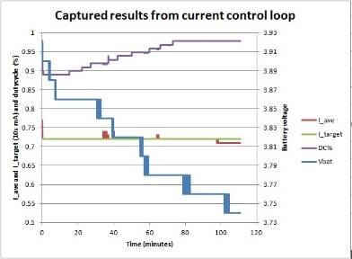
genebren had been blogging on a smart solar lighting system that he had been developing for the past two months (Smart Solar Lighting Project - Initial design ideas, Smart Solar Lighting Project - Detailed design, Smart Solar Lighting Project - Mechanical designs and Smart Solar Lighting Project - Update 10/8/2020). It is somewhat fortuitous that he was coming up on one of his milestones (code closed loop PWM function to normalize LED current over the range of battery voltage (he was thinking of a simple PID loop to adjust PWM to achieve desired LED current)) as this competition was running (actually close to ending).
His goal was to provide a way to control his LED current across a wide range of battery voltage (Li-Ion , 4.2 to 3.0V). Initially, during his design phase, he had decided on having two current monitors, each allowing the measurement of the current through a pair of LEDs. He had thought about a constant current source as a control element, but instead decided to utilize a software controlled, PWM driver to power my LEDs.
Exploring Linear Voltage Regulation by fmilburn:
Community Member Scoring:
Grand Prize: 2 points First Place: 1 points Total Points: 3 Points
For inspiration he relies on Chapter 9 of The Art of Electronics Third Edition by Horowitz and Hill is about Voltage Regulation and Power Conversion. Horowitz and Hill is not light reading, but the tutorial on designing a linear regulator is a great example of the clear and concise way they convey information.
| ||||||||||||||||||||||||||||||
| The Runners Up | Runners Up:
The following members received first place votes.
Simple Electronic Control Systems by Jan Cumps:
Control systems can be complex. With a number of analogue or digital components to keep a circuit "under control". This one uses a single transistor. And it uses that transistor's inherent characteristics to provide a tight, closed control loop. Jan Cumps does a theoretical analysis, and then check the reality on a breadboard. If you're new to bipolar transistors, this post may help you "to think like a transistor".
Auto-tuning high current dual-channel motor control unit. by shreyasborse:
A single module that performs the tasks of dual motor control and thereby making it simpler by implementing auto-tuning and motor control algorithms that support high current drive applications. The module is designed to support UART communication for IoT based industrial applications. The concept proposes the idea of implementing motor control by real-time simulation to obtain accurate run-time control parameters. The module is designed to communicate with other similar modules by creating a network that is connected over a single UART channel and controlled by a single master micro-controller. Further, it explains the functions that are built to process the constants resulting from the model and executing on the hardware we built. The motor-controller is developed using STM VNH5019A-E and Arduino Micro ATMega32u4. The basic purpose of integrating the micro-controller was for the auto-tuning of motors and for establishing communication with external controllers. The Arduino Micro performs the auto-tuning task when interfaced with MATLAB Simulink in external mode. The main purpose of considering Arduino Micro as the on-board micro-controller is because there is an Arduino Hardware add-on that Simulink supports which is lucid to develop and deploy. Also, Arduino Micro has the provision of UART communication and five external interrupt pins that are required to interface with incremental encoders. The onboard micro-controller is also fed with different drive functions which makes the motor controlling task very easy for naive users. We have built functions including acceleration, de-acceleration, 2-wheel drive equation, position tuning which are used for embedded robotics applications.
What's Cooking with that reflow oven of yours by BigG:
Now that BigG has passed the design-a-PCB-and-get- it-made phase, he's been toying with the idea of making his own reflow oven. So he took the step and did what many others have done - he bought a cheap toaster oven. He even purchased an off-the-shelf reflow oven controller unit from another maker on Tindie (details of the controller unit can be found on their GitHub page: https://github.com/UnexpectedMaker/ReflowMaster). That was well over a year ago. The problem was, while waiting for the arrival of the controller unit, he discovered that the toaster oven is perfect for reheating left over pizza slices and thus shelved that idea of repurposing the toaster oven. Then his local supermarket had slow cookers on special offer for less than $15. This caught his eye as these were much cheaper than toaster ovens and it used way less energy (150W versus circa 1500W for a toaster oven). So, even though he could readily see that a slow cooker would not reflow a PCB correctly, if at all, straight out the box, he was nevertheless optimistic that with a little a bit of engineering/hacking he could repurpose this slow cooker for reflow. So he went ahead and bought one.
Running in circles ? Make it perfect circles with regulators by robogary:
Try to run a 2 motor robot in a perfect circle by itself.......It wont :-( There are many variables that prevent perfection: wheel friction, wheel motor speed mismatches, gear backlash, wheel slip, wheel diameter mismatches, varying battery voltage, motor differences, AND resolution of the PWM controlling the motor speed. However ....applying a simple error correction system while the robot circles...the results are pretty amazing. First, let's understand how the robot drives in a circle. Theoretically, tracing out a circle should be easy, its just a ratio of wheel position (and speeds) The ratio is difficult to maintain precisely, and there are so many variables..... BUT by using motor encoder to regulate motor speed or use the distance traveled of the to adjust the motor speed to keep that circle perfect. My control solution is determining the traveled position of each wheel ( which also has to be be at the same ratio of inner circle to outer circle diameter). if the traveled position of the right side wheel is not as calculated for a perfect circle to what the left wheel has traveled, it's speed reference can be sped up or slowed down, applying a correction to compensate for errors. The Arduino program speeds up or slows down the right hand side wheel speed by 2% when the actual encoder counts are + or - 10 counts off from calculated value. This robot has a MKR1000 for brains, a motor carrier shield for variable speed motor control, and inputs for the motor encoders.
Home Air Quality Control System by cmelement14:
cmelement14 's project is a simple on/off control system. It is a supplemental home air quality controller to my ecobee thermostat system. The ecobee thermostat has control to my air conditioner, furnace and ventilation fans. It does a good to control his home temperature. However, home air quality is also very important to our health. Especially in this COVID-19 era, we work and live at home all the time. Adding air quality monitoring and control to my ecobee system becomes important. An environment click board (i.e., Bosch BME680 sensor on board) is plugged into the Raspberry Pi 3 through a Pi 3 click shield board. The sensor is sampling VOC (Volatile Organic compounds gases) raw values which is processed by Bosch Sensortec Environmental Cluster (BSEC) software module and eventually transformed into air quality index numbers. When the index number is greater or lower than high/low thresholds, the Pi3 will communicate to the ecobee system (https://api.ecobee.com) using ecobee API through the my home network system. If the indoor air quality is deteriorated, the RPi3 can command ecobee to turn on the ventilation system so fresh air can be brought into house to improve air quality.
To summarize, the system involves the following activities: 1. Sensor acquires raw data (temperature, pressure, humidity and gas VOC); 2. BSEC software (in C) processes data and outputs AQI number; 3. Application software (in Python) communicates with ecobee through APIs; 4. ecobee turns on/off fan as needed.
| ||||||||||||||||||||||||||||||


What's Happening Now
There's always stuff going on in the community and the best ideas always come from you. Suggest your idea in the Monthly Poll, and vote on the themes you want to do projects on. Build sensor related projects. You can design a sensors, use a sensor in a control system, or do something interesting with sensor data in the Sensors competition. Or, build projects that involve taking any unused appliance, such as an old radio or game console, and upcycle it using electronics of your choice in the Recycle & Retrofit competition.


In the comments below:
Top Comments
-

gecoz
-
Cancel
-
Vote Up
+2
Vote Down
-
-
Sign in to reply
-
More
-
Cancel
Comment-

gecoz
-
Cancel
-
Vote Up
+2
Vote Down
-
-
Sign in to reply
-
More
-
Cancel
Children